
Product Guide
Page 1
Intel® Server Board S815EBM1 Product Guide A Guide for Technically Qualified Assemblers of Intel® Identified Subassemblies/Products Order Number: A67054-003 1
Intel® Server Board S815EBM1 Product Guide A Guide for Technically Qualified Assemblers of Intel® Identified Subassemblies/Products Order Number: A67054-003 1
Product Guide
Page 3
... ...7 Back Panel Connectors 8 Front Panel Connectors 9 Server Board Connector and Component Locations 10 Processors ...11 Memory ...11 Intel® 82815E Graphics Memory Controller Hub (GMCH 12 Intel® 82801BA I/O Controller Hub (ICH2 13 Firmware Hub (FWH 13 Input/Output (I/O) Controller 13 Real-Time Clock......20 DIMM Installation Guidelines 20 Installing DIMMs ...20 Removing DIMMs ...21 Installing the I/O Shield...22 Installing the Server Board 23 Installing a Processor ...24 Removing the Processor ...26 Installing a 1 GHz Processor Heatsink 27 Removing the 1 GHz Processor 30 iii
... ...7 Back Panel Connectors 8 Front Panel Connectors 9 Server Board Connector and Component Locations 10 Processors ...11 Memory ...11 Intel® 82815E Graphics Memory Controller Hub (GMCH 12 Intel® 82801BA I/O Controller Hub (ICH2 13 Firmware Hub (FWH 13 Input/Output (I/O) Controller 13 Real-Time Clock......20 DIMM Installation Guidelines 20 Installing DIMMs ...20 Removing DIMMs ...21 Installing the I/O Shield...22 Installing the Server Board 23 Installing a Processor ...24 Removing the Processor ...26 Installing a 1 GHz Processor Heatsink 27 Removing the 1 GHz Processor 30 iii
Product Guide
Page 4
... Setting the BIOS Configuration Jumper 35 Clearing the Passwords...36 3 Configuration Software and Utilities Updating the BIOS with the Intel® Express BIOS Update Utility 37 Updating the BIOS with the Intel® Flash Memory Update Utility 37 Preparing for the Update 37 Obtaining the BIOS Update File 38 Recording the Current... 60 Removable Devices Submenu 60 ATAPI CDROM Drives Submenu 61 Exit Menu ...62 4 Solving BIOS Problems BIOS Beep Codes ...63 BIOS Error Messages ...64 iv Intel Server Board S815EBM1 Product Guide
... Setting the BIOS Configuration Jumper 35 Clearing the Passwords...36 3 Configuration Software and Utilities Updating the BIOS with the Intel® Express BIOS Update Utility 37 Updating the BIOS with the Intel® Flash Memory Update Utility 37 Preparing for the Update 37 Obtaining the BIOS Update File 38 Recording the Current... 60 Removable Devices Submenu 60 ATAPI CDROM Drives Submenu 61 Exit Menu ...62 4 Solving BIOS Problems BIOS Beep Codes ...63 BIOS Error Messages ...64 iv Intel Server Board S815EBM1 Product Guide
Product Guide
Page 5
... Connector ...29 16. Lowering the Plastic Clip Handle 28 14. Connector Groups...67 Contents v 5 Technical Reference Server Board Connectors 67 Baseboard Connectors 68 Power and Hardware Control Connectors 68 Add-In Board and Peripheral Interface Connectors 69 Server Board Resources ...70 Memory Map ...70 DMA Channels ...70 I /O Shield Dimensions 22 6. Connecting the Processor Fan Cable...
... Connector ...29 16. Lowering the Plastic Clip Handle 28 14. Connector Groups...67 Contents v 5 Technical Reference Server Board Connectors 67 Baseboard Connectors 68 Power and Hardware Control Connectors 68 Add-In Board and Peripheral Interface Connectors 69 Server Board Resources ...70 Memory Map ...70 DMA Channels ...70 I /O Shield Dimensions 22 6. Connecting the Processor Fan Cable...
Product Guide
Page 6
.... Processor and Memory Module Combinations 12 4. 21. Peripheral Configuration Submenu 49 15. Diskette Configuration Submenu 53 18. PCI Configuration Submenu 47 13. Interrupts ...72 vi Intel Server Board S815EBM1 Product Guide Jumper Settings for the BIOS Setup Program Modes 35 6. Extended Configuration Submenu 44 10. Boot Menu ...58 24. ATAPI CDROM Drives Submenu 61...
.... Processor and Memory Module Combinations 12 4. 21. Peripheral Configuration Submenu 49 15. Diskette Configuration Submenu 53 18. PCI Configuration Submenu 47 13. Interrupts ...72 vi Intel Server Board S815EBM1 Product Guide Jumper Settings for the BIOS Setup Program Modes 35 6. Extended Configuration Submenu 44 10. Boot Menu ...58 24. ATAPI CDROM Drives Submenu 61...

Product Guide
Page 7
... wake up to 512 MB system memory • Support for single row or double row DIMMs The S815EBM1 board includes the Intel® 815E Chipset, consisting of: • Intel® 82815 Graphics and Memory Controller Hub (GMCH) • Intel® 82801BA I/O Controller Hub (ICH2) • 4 Mbit Firmware Hub (FWH) (STM M50FW040 or ...drive interface • PS/2† keyboard and mouse ports Allows add-in SCSI controllers to PCI slot 2, S5 wake from all PCI slots). Server Board Features Feature Processors Memory Chipset I /O controller. • One back panel serial port; 1 Description...
... wake up to 512 MB system memory • Support for single row or double row DIMMs The S815EBM1 board includes the Intel® 815E Chipset, consisting of: • Intel® 82815 Graphics and Memory Controller Hub (GMCH) • Intel® 82801BA I/O Controller Hub (ICH2) • 4 Mbit Firmware Hub (FWH) (STM M50FW040 or ...drive interface • PS/2† keyboard and mouse ports Allows add-in SCSI controllers to PCI slot 2, S5 wake from all PCI slots). Server Board Features Feature Processors Memory Chipset I /O controller. • One back panel serial port; 1 Description...
Product Guide
Page 8
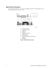
Serial port A, teal H. The figure legend below lists the colors used. PS/2 keyboard, purple C. USB port 1 D. VGA port, blue G. Back Panel Connectors 8 Intel Server Board S815EBM1 Product Guide USB port 0 J. A E H C BD F G IJ OM12208 A. Parallel port, burgundy F. USB port 2 Figure 1. RJ-45 LAN connector with PC 99 recommendations. Back Panel Connectors The back panel connectors are color-coded in compliance with LED display I. PS/2 mouse, green B. USB port 3 E.
Serial port A, teal H. The figure legend below lists the colors used. PS/2 keyboard, purple C. USB port 1 D. VGA port, blue G. Back Panel Connectors 8 Intel Server Board S815EBM1 Product Guide USB port 0 J. A E H C BD F G IJ OM12208 A. Parallel port, burgundy F. USB port 2 Figure 1. RJ-45 LAN connector with PC 99 recommendations. Back Panel Connectors The back panel connectors are color-coded in compliance with LED display I. PS/2 mouse, green B. USB port 3 E.
Product Guide
Page 11
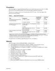
... Dual Inline Memory Modules (DIMMs) with the server board and must be purchased separately. Table 2. Processors The board supports a single Intel Pentium III processor or Intel Celeron processor above 533 MHz. customers can determine S815EBM1 support at : http://support.intel.com/support/motherboards/server/S815EBM1/ For instructions on processor support for the boards, refer to the slowest speed DIMM installed Description...
... Dual Inline Memory Modules (DIMMs) with the server board and must be purchased separately. Table 2. Processors The board supports a single Intel Pentium III processor or Intel Celeron processor above 533 MHz. customers can determine S815EBM1 support at : http://support.intel.com/support/motherboards/server/S815EBM1/ For instructions on processor support for the boards, refer to the slowest speed DIMM installed Description...
Product Guide
Page 12
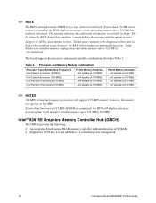
... ACPI Rev 2.0 and APM Rev 1.2 compliant power management. 12 Intel Server Board S815EBM1 Product Guide The first time the BIOS detects this condition, a pause follows the message with autodetection of 133 MHz SDRAM are populated, the BIOS will not pause on subsequent detection. The board supports the processor and memory module combinations shown in Setup...
... ACPI Rev 2.0 and APM Rev 1.2 compliant power management. 12 Intel Server Board S815EBM1 Product Guide The first time the BIOS detects this condition, a pause follows the message with autodetection of 133 MHz SDRAM are populated, the BIOS will not pause on subsequent detection. The board supports the processor and memory module combinations shown in Setup...
Product Guide
Page 13
... System BIOS Input/Output (I/O) Controller The boards support the SMSC LPC47M132 I/O controller. Description 13 The SMSC LPC47M132 I/O controller features the following: • One parallel port with UHCI. Intel® 82801BA I/O Controller Hub (ICH2) The Intel 82801BA ICH2 has these features: • ... attach more than four devices, connect an external hub to either of standard software drivers written to the server without an external hub. The server board supports the UHCI specification and takes advantage of the built-in a Universal Host Controller Interface (UHCI) implementation...
... System BIOS Input/Output (I/O) Controller The boards support the SMSC LPC47M132 I/O controller. Description 13 The SMSC LPC47M132 I/O controller features the following: • One parallel port with UHCI. Intel® 82801BA I/O Controller Hub (ICH2) The Intel 82801BA ICH2 has these features: • ... attach more than four devices, connect an external hub to either of standard software drivers written to the server without an external hub. The server board supports the UHCI specification and takes advantage of the built-in a Universal Host Controller Interface (UHCI) implementation...
Product Guide
Page 14
...add-in Chapter 3. ✏ NOTE Server systems that have an unshielded cable attached to a USB port might not meet FCC Class B requirements even if no device or a low-speed USB device is attached to Setup. 14 Intel Server Board S815EBM1 Product Guide If only the supervisor password... is stored in board. Use a shielded cable that meets the requirements for that add-in the Firmware Hub. The interface ...
...add-in Chapter 3. ✏ NOTE Server systems that have an unshielded cable attached to a USB port might not meet FCC Class B requirements even if no device or a low-speed USB device is attached to Setup. 14 Intel Server Board S815EBM1 Product Guide If only the supervisor password... is stored in board. Use a shielded cable that meets the requirements for that add-in the Firmware Hub. The interface ...
Product Guide
Page 15
...code (beep code) information during the Power-On Self-Test (POST). the LAN subsystem is mounted on Intel's support web site at: http://support.intel.com/support/motherboards/server/S815EBM1/ Description 15 Features include: • 32-bit, 33-MHz direct bus mastering on whether the supervisor or... • Jumperless configuration; • If both the supervisor and user passwords are set, you can boot the server. If only the supervisor password is booted. LAN Subsystem The Intel® 82562ET (in the host memory that copies data directly to the S815EBM1, link on the server board.
...code (beep code) information during the Power-On Self-Test (POST). the LAN subsystem is mounted on Intel's support web site at: http://support.intel.com/support/motherboards/server/S815EBM1/ Description 15 Features include: • 32-bit, 33-MHz direct bus mastering on whether the supervisor or... • Jumperless configuration; • If both the supervisor and user passwords are set, you can boot the server. If only the supervisor password is booted. LAN Subsystem The Intel® 82562ET (in the host memory that copies data directly to the S815EBM1, link on the server board.
Product Guide
Page 16
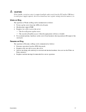
...with an ACPI-aware operating system, the BIOS can damage the power supply. 16 Intel Server Board S815EBM1 Product Guide Failure to provide adequate standby current when implementing Wake on how to APM support. The server is turned off. Power Management Features Power management is implemented at several levels, including:...PCI slots Wake on Ring Resume on Ring If the board is used with another server on the server board keeps the values in CMOS RAM and the clock current when the server is communicating with PCI bus network adapters that are built into the RJ-45...
...with an ACPI-aware operating system, the BIOS can damage the power supply. 16 Intel Server Board S815EBM1 Product Guide Failure to provide adequate standby current when implementing Wake on how to APM support. The server is turned off. Power Management Features Power management is implemented at several levels, including:...PCI slots Wake on Ring Resume on Ring If the board is used with another server on the server board keeps the values in CMOS RAM and the clock current when the server is communicating with PCI bus network adapters that are built into the RJ-45...
Product Guide
Page 17
...Requires modem interrupt be summarized as follows: • Resumes operation from the PCI and/or USB buses exceeds power supply capacity, the server board may lose register settings stored in memory, etc. CAUTION If the standby current necessary to support multiple wake events from the APM sleep ...8226; Modem must support PME. • Requires two calls to access the server. • Detects incoming call enables access (when the appropriate software is loaded). • For external modems, hardware on the server board monitors the ring indicate (RI) input of Wake on Ring can be ...
...Requires modem interrupt be summarized as follows: • Resumes operation from the PCI and/or USB buses exceeds power supply capacity, the server board may lose register settings stored in memory, etc. CAUTION If the standby current necessary to support multiple wake events from the APM sleep ...8226; Modem must support PME. • Requires two calls to access the server. • Detects incoming call enables access (when the appropriate software is loaded). • For external modems, hardware on the server board monitors the ring indicate (RI) input of Wake on Ring can be ...

Product Guide
Page 19
...the system AC power. grip the narrow sides of fine needle nosed pliers. Do not slide board over two jumper pins. Only a technically qualified person should configure the server board. WARNING Hazardous conditions, devices & cables: Hazardous electrical conditions may bend or break the stake... pins on /off: The power button DOES NOT turn off the server and disconnect the power cord, telecommunications systems, ...
...the system AC power. grip the narrow sides of fine needle nosed pliers. Do not slide board over two jumper pins. Only a technically qualified person should configure the server board. WARNING Hazardous conditions, devices & cables: Hazardous electrical conditions may bend or break the stake... pins on /off: The power button DOES NOT turn off the server and disconnect the power cord, telecommunications systems, ...
Product Guide
Page 20
...Installation Guidelines All memory components and DIMMs used with the boards must comply with all peripheral devices connected to the server. Turn off the server and disconnect the AC power cord. 20 Intel Server Board S815EBM1 Product Guide You can access these documents through the ...Internet at: http://www.intel.com/design/chipsets/memory/ Installing DIMMs To install...
...Installation Guidelines All memory components and DIMMs used with the boards must comply with all peripheral devices connected to the server. Turn off the server and disconnect the AC power cord. 20 Intel Server Board S815EBM1 Product Guide You can access these documents through the ...Internet at: http://www.intel.com/design/chipsets/memory/ Installing DIMMs To install...
Product Guide
Page 22
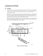
...the shield doesn't fit, obtain a proper-sized shield from the chassis vendor. When installed in the chassis. Install the I/O shield before installing the server board in the chassis, the shield blocks radio frequency transmissions, protects internal components from dust and foreign objects, and promotes correct airflow within the chassis. ... Place the shield inside the chassis and press the shield into place so that it fits tightly and securely. The boxed server board comes with an improperly installed I /O Shield Dimensions OM12390 22 Intel Server Board S815EBM1 Product Guide
...the shield doesn't fit, obtain a proper-sized shield from the chassis vendor. When installed in the chassis. Install the I/O shield before installing the server board in the chassis, the shield blocks radio frequency transmissions, protects internal components from dust and foreign objects, and promotes correct airflow within the chassis. ... Place the shield inside the chassis and press the shield into place so that it fits tightly and securely. The boxed server board comes with an improperly installed I /O Shield Dimensions OM12390 22 Intel Server Board S815EBM1 Product Guide
Product Guide
Page 23
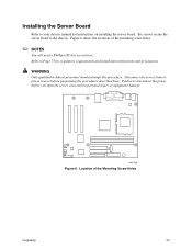
... shows the locations of the Mounting Screw Holes Upgrading 23 Failure to the chassis. Installing the Server Board Refer to your chassis manual for regulatory requirements and installation instructions and precautions. WARNING Only qualified ...screwdriver. Refer to Page 73 for instructions on installing the server board. Disconnect the server from its power source before you open the server can result in personal injury or equipment damage. OM12203 Figure 6. Six screws secure the server board to disconnect the power before performing the procedures described here...
... shows the locations of the Mounting Screw Holes Upgrading 23 Failure to the chassis. Installing the Server Board Refer to your chassis manual for regulatory requirements and installation instructions and precautions. WARNING Only qualified ...screwdriver. Refer to Page 73 for instructions on installing the server board. Disconnect the server from its power source before you open the server can result in personal injury or equipment damage. OM12203 Figure 6. Six screws secure the server board to disconnect the power before performing the procedures described here...
Product Guide
Page 24
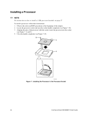
... these instructions: 1. B C A D OM11065 Figure 7. Locate the processor socket and raise the socket handle completely (see page 27. Installing the Processor in the Processor Socket 24 Intel Server Board S815EBM1 Product Guide Installing a Processor ✏ NOTE For instructions on how to install a 1 GHz processor heatsink, see Figure 7, B). 3.
... these instructions: 1. B C A D OM11065 Figure 7. Locate the processor socket and raise the socket handle completely (see page 27. Installing the Processor in the Processor Socket 24 Intel Server Board S815EBM1 Product Guide Installing a Processor ✏ NOTE For instructions on how to install a 1 GHz processor heatsink, see Figure 7, B). 3.
Product Guide
Page 26
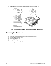
Observe the safety and ESD precautions at the beginning of this chapter. 2. Detach the fan heatsink clips. 4. J1B1 J1B1 PGA370 OM11156 Figure 10. Raise the socket handle completely. 6. Remove the processor. 26 Intel Server Board S815EBM1 Product Guide Remove the heatsink. 5. Disconnect the processor fan cable. 3. Connect the processor fan cable to the Processor Fan Connector Removing the Processor To remove the processor, follow these instructions: 1. Connecting the Processor Fan Cable to the processor fan connector (see Figure 10). 7.
Observe the safety and ESD precautions at the beginning of this chapter. 2. Detach the fan heatsink clips. 4. J1B1 J1B1 PGA370 OM11156 Figure 10. Raise the socket handle completely. 6. Remove the processor. 26 Intel Server Board S815EBM1 Product Guide Remove the heatsink. 5. Disconnect the processor fan cable. 3. Connect the processor fan cable to the Processor Fan Connector Removing the Processor To remove the processor, follow these instructions: 1. Connecting the Processor Fan Cable to the processor fan connector (see Figure 10). 7.


