Product Guide
Page 4
...Connecting the IDE Cable 34 Setting the BIOS Configuration Jumper 35 Clearing the Passwords...36 3 Configuration Software and Utilities Updating the BIOS with the Intel® Express BIOS Update Utility 37 Updating the BIOS with the Intel® Flash Memory Update Utility 37 Preparing for the Update 37 Obtaining the BIOS Update File 38 Recording the Current BIOS Settings 38 Creating Bootable Media 38 Creating a Bootable Diskette 39 Creating a BIOS Update Media 39 Updating the BIOS ...40 Recovering the BIOS...41 Using the Setup Program 42 BIOS Setup Program Modes 42 Maintenance Menu...
...Connecting the IDE Cable 34 Setting the BIOS Configuration Jumper 35 Clearing the Passwords...36 3 Configuration Software and Utilities Updating the BIOS with the Intel® Express BIOS Update Utility 37 Updating the BIOS with the Intel® Flash Memory Update Utility 37 Preparing for the Update 37 Obtaining the BIOS Update File 38 Recording the Current BIOS Settings 38 Creating Bootable Media 38 Creating a Bootable Diskette 39 Creating a BIOS Update Media 39 Updating the BIOS ...40 Recovering the BIOS...41 Using the Setup Program 42 BIOS Setup Program Modes 42 Maintenance Menu...
Product Guide
Page 5
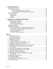
... 1. Connecting the IDE Cable 34 19. Server Board Components 10 4. Removing the Battery 33 18. Placing the Plastic Clip Over the Fan Heatsink 28 13. Installing the Processor in the Processor Socket 24 8. 5 Technical Reference Server Board Connectors 67 Baseboard Connectors 68 Power and Hardware Control Connectors 68 Add-In Board and Peripheral Interface Connectors 69 Server Board Resources ...70 Memory Map ...70 DMA Channels ...70 I /O Shield Dimensions 22 6. Connector Groups...67 Contents v Front Panel Connectors 9 3. Attaching the Fan Heatsink Clips...
... 1. Connecting the IDE Cable 34 19. Server Board Components 10 4. Removing the Battery 33 18. Placing the Plastic Clip Over the Fan Heatsink 28 13. Installing the Processor in the Processor Socket 24 8. 5 Technical Reference Server Board Connectors 67 Baseboard Connectors 68 Power and Hardware Control Connectors 68 Add-In Board and Peripheral Interface Connectors 69 Server Board Resources ...70 Memory Map ...70 DMA Channels ...70 I /O Shield Dimensions 22 6. Connector Groups...67 Contents v Front Panel Connectors 9 3. Attaching the Fan Heatsink Clips...
Product Guide
Page 6
.../Secondary IDE Master/Slave Submenus 51 17. Boot Menu ...58 24. Hard Disk Drives Submenu 60 26. Interrupts ...72 vi Intel Server Board S815EBM1 Product Guide Jumper Settings for the BIOS Setup Program Modes 35 6. Power Menu...56 21. ATAPI CDROM Drives Submenu 61 28. Exit Menu...62 29. BIOS Error Messages 64 31. DMA Channels...70 33. RJ-45 LAN Connector LEDs 16 5. BIOS Setup Program Function Keys 43 8. Peripheral Configuration Submenu 49 15. Event Log Configuration Submenu 54 19. ACPI...
.../Secondary IDE Master/Slave Submenus 51 17. Boot Menu ...58 24. Hard Disk Drives Submenu 60 26. Interrupts ...72 vi Intel Server Board S815EBM1 Product Guide Jumper Settings for the BIOS Setup Program Modes 35 6. Power Menu...56 21. ATAPI CDROM Drives Submenu 61 28. Exit Menu...62 29. BIOS Error Messages 64 31. DMA Channels...70 33. RJ-45 LAN Connector LEDs 16 5. BIOS Setup Program Function Keys 43 8. Peripheral Configuration Submenu 49 15. Event Log Configuration Submenu 54 19. ACPI...

Product Guide
Page 7
... Graphics and Memory Controller Hub (GMCH) • Intel® 82801BA I/O Controller Hub (ICH2) • 4 Mbit Firmware Hub (FWH) (STM M50FW040 or equivalent) SMSC LPC47M132 LPC bus I/O controller. • One back panel serial port; 1 Description Server Board Features Table 1. Three PCI bus expansion slots (SMBus routed to 512 MB system memory • Support for up capability. Server Board Features Feature Processors Memory Chipset I /O controller. Support for: • Advanced Power Management (APM) • Advanced Configuration and Power Interface (ACPI) • Plug and...
... Graphics and Memory Controller Hub (GMCH) • Intel® 82801BA I/O Controller Hub (ICH2) • 4 Mbit Firmware Hub (FWH) (STM M50FW040 or equivalent) SMSC LPC47M132 LPC bus I/O controller. • One back panel serial port; 1 Description Server Board Features Table 1. Three PCI bus expansion slots (SMBus routed to 512 MB system memory • Support for up capability. Server Board Features Feature Processors Memory Chipset I /O controller. Support for: • Advanced Power Management (APM) • Advanced Configuration and Power Interface (ACPI) • Plug and...
Product Guide
Page 13
... LAN media access controller. • Universal Serial Bus Interface with two USB controllers providing four back panel ports in ports. Description 13 The SMSC LPC47M132 I /O controller. A battery on the board keeps the clock current when the server is turned off. Intel® 82801BA I/O Controller Hub (ICH2) The Intel 82801BA ICH2 has these features: • 33 MHz Peripheral Component Interface (PCI) Local Bus slots supporting PCI specification, Rev 2.2. • Support for the System Management Bus routed to: PCI Slot...
... LAN media access controller. • Universal Serial Bus Interface with two USB controllers providing four back panel ports in ports. Description 13 The SMSC LPC47M132 I /O controller. A battery on the board keeps the clock current when the server is turned off. Intel® 82801BA I/O Controller Hub (ICH2) The Intel 82801BA ICH2 has these features: • 33 MHz Peripheral Component Interface (PCI) Local Bus slots supporting PCI specification, Rev 2.2. • Support for the System Management Bus routed to: PCI Slot...
Product Guide
Page 14
... Intel Server Board S815EBM1 Product Guide Use a shielded cable that meets the requirements for that restrict whether the BIOS Setup program can boot the server. IDE Auto Configuration If you install a PCI add-in board in Chapter 3. Security Passwords The BIOS includes security features that add-in board connectors. The BIOS can be accessed and who can be upgraded by following restrictions: • The supervisor password gives unrestricted access to four IDE devices (such as a hard drive) in your server, the IDE auto-configuration utility...
... Intel Server Board S815EBM1 Product Guide Use a shielded cable that meets the requirements for that restrict whether the BIOS Setup program can boot the server. IDE Auto Configuration If you install a PCI add-in board in Chapter 3. Security Passwords The BIOS includes security features that add-in board connectors. The BIOS can be accessed and who can be upgraded by following restrictions: • The supervisor password gives unrestricted access to four IDE devices (such as a hard drive) in your server, the IDE auto-configuration utility...
Product Guide
Page 15
... and user passwords are set , the server boots without asking for a password. Speaker A 47 Ω inductive speaker is booted. Setup options are set, you must enter either password to access Setup. Features include: • 32-bit, 33-MHz direct bus mastering on Intel's support web site at: http://support.intel.com/support/motherboards/server/S815EBM1/ Description 15 The Intel 82562ET provides the following functions: • Basic 10/100 Ethernet LAN connectivity • Supports RJ-45 connector with status indicator LEDs • Full driver compatibility...
... and user passwords are set , the server boots without asking for a password. Speaker A 47 Ω inductive speaker is booted. Setup options are set, you must enter either password to access Setup. Features include: • 32-bit, 33-MHz direct bus mastering on Intel's support web site at: http://support.intel.com/support/motherboards/server/S815EBM1/ Description 15 The Intel 82562ET provides the following functions: • Basic 10/100 Ethernet LAN connectivity • Supports RJ-45 connector with status indicator LEDs • Full driver compatibility...
Product Guide
Page 16
... instructions on LAN technology can damage the power supply. 16 Intel Server Board S815EBM1 Product Guide CAUTION For Wake on LAN technology, the 5 V standby line for the location of providing adequate +5 V standby current. Failure to provide adequate standby current when implementing Wake on how to APM support. Network adapters that have a remote wake-up and the LAN subsystem is used with another server on the server board keeps the values in CMOS RAM and the clock current...
... instructions on LAN technology can damage the power supply. 16 Intel Server Board S815EBM1 Product Guide CAUTION For Wake on LAN technology, the 5 V standby line for the location of providing adequate +5 V standby current. Failure to provide adequate standby current when implementing Wake on how to APM support. Network adapters that have a remote wake-up and the LAN subsystem is used with another server on the server board keeps the values in CMOS RAM and the clock current...
Product Guide
Page 20
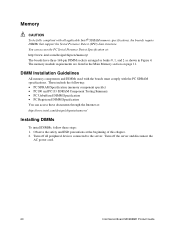
... Installation Guidelines All memory components and DIMMs used with the boards must comply with all peripheral devices connected to the server. Turn off the server and disconnect the AC power cord. 20 Intel Server Board S815EBM1 Product Guide Observe the safety and ESD precautions at : http://www.intel.com/design/chipsets/memory/ Installing DIMMs To install DIMMs, follow these steps: 1. Turn off all applicable Intel ® SDRAM memory specifications, the boards require DIMMs that support the Serial...
... Installation Guidelines All memory components and DIMMs used with the boards must comply with all peripheral devices connected to the server. Turn off the server and disconnect the AC power cord. 20 Intel Server Board S815EBM1 Product Guide Observe the safety and ESD precautions at : http://www.intel.com/design/chipsets/memory/ Installing DIMMs To install DIMMs, follow these steps: 1. Turn off all applicable Intel ® SDRAM memory specifications, the boards require DIMMs that support the Serial...
Product Guide
Page 35
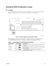
... 3 1 Configuration The BIOS uses current configuration information and passwords for the Setup program modes. The maintenance menu is required. A recovery diskette is displayed. Setting the BIOS Configuration Jumper CAUTION Always turn off the power and unplug the power cord from the server before changing the jumper. After the POST runs, Setup runs automatically. Moving the jumper with the power on may result in BIOS Setup. BIOS Configuration Jumper Block Location OM12206 This three-pin jumper block, shown in Figure 19, enables all server board configurations to...
... 3 1 Configuration The BIOS uses current configuration information and passwords for the Setup program modes. The maintenance menu is required. A recovery diskette is displayed. Setting the BIOS Configuration Jumper CAUTION Always turn off the power and unplug the power cord from the server before changing the jumper. After the POST runs, Setup runs automatically. Moving the jumper with the power on may result in BIOS Setup. BIOS Configuration Jumper Block Location OM12206 This three-pin jumper block, shown in Figure 19, enables all server board configurations to...
Product Guide
Page 36
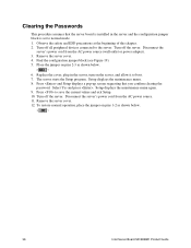
... Setup. 10. Remove the server cover. 4. Replace the cover, plug in the server and the configuration jumper block is set to boot. 7. Select Yes and press . Remove the server cover. 12. To restore normal operation, place the jumper on pins 2-3 as shown below . 3 1 6. The server starts the Setup program. Press and Setup displays a pop-up screen requesting that the server board is installed in the server, turn on the server, and allow it to normal mode. 1. Clearing the Passwords...
... Setup. 10. Remove the server cover. 4. Replace the cover, plug in the server and the configuration jumper block is set to boot. 7. Select Yes and press . Remove the server cover. 12. To restore normal operation, place the jumper on pins 2-3 as shown below . 3 1 6. The server starts the Setup program. Press and Setup displays a pop-up screen requesting that the server board is installed in the server, turn on the server, and allow it to normal mode. 1. Clearing the Passwords...
Product Guide
Page 42
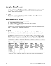
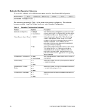
... Intel Server Board S815EBM1 Product Guide The BIOS Setup program can use the BIOS Setup program to the settings, update this section apply to access the BIOS Setup program and lists Setup features, options, and default settings. ✏ NOTE For reference purposes, you how to the server boards with BIOS identifier EA815.20A.86B Server boards with other BIOS identifiers might have differences in this record. BIOS Setup Program Menu Bar Maintenance Main Advanced Clears passwords and Boot Integrity Service (BIS)* credentials, and configures extended configuration memory settings...
... Intel Server Board S815EBM1 Product Guide The BIOS Setup program can use the BIOS Setup program to the settings, update this section apply to access the BIOS Setup program and lists Setup features, options, and default settings. ✏ NOTE For reference purposes, you how to the server boards with BIOS identifier EA815.20A.86B Server boards with other BIOS identifiers might have differences in this record. BIOS Setup Program Menu Bar Maintenance Main Advanced Clears passwords and Boot Integrity Service (BIS)* credentials, and configures extended configuration memory settings...
Product Guide
Page 44
... the video driver and the application must support Write Combining. Cache lookups are written to CAS# Delay SDRAM RAS# Precharge • Auto • User Defined • 3 • 2 • Auto • 3 • 2 • Auto • 3 • 2 • Auto Description User Defined allows setting memory control and video memory cache mode. Selects the number of time required before accessing a new row. 44 Intel Server Board S815EBM1 Product Guide Full 32 byte contents of clock...
... the video driver and the application must support Write Combining. Cache lookups are written to CAS# Delay SDRAM RAS# Precharge • Auto • User Defined • 3 • 2 • Auto • 3 • 2 • Auto • 3 • 2 • Auto Description User Defined allows setting memory control and video memory cache mode. Selects the number of time required before accessing a new row. 44 Intel Server Board S815EBM1 Product Guide Full 32 byte contents of clock...
Product Guide
Page 45
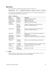
... default language used by the BIOS. Processor Serial Number System Time System Date • Disabled • Enabled Hour, minute, and second Day of the screen. Configuration Software and Utilities 45 Table 10. Displays CPU internal cache and, if enabled, select WriteThru or WriteBack mechanism. Displays the amount and type of RAM. Displays CPU external cache and, if enabled, select WriteThru or WriteBack mechanism. Displays processor speed. Displays the total amount of RAM in the memory banks. Main Menu Feature BIOS Version Processor Type Processor Speed...
... default language used by the BIOS. Processor Serial Number System Time System Date • Disabled • Enabled Hour, minute, and second Day of the screen. Configuration Software and Utilities 45 Table 10. Displays CPU internal cache and, if enabled, select WriteThru or WriteBack mechanism. Displays the amount and type of RAM. Displays CPU external cache and, if enabled, select WriteThru or WriteBack mechanism. Displays processor speed. Displays the total amount of RAM in the memory banks. Main Menu Feature BIOS Version Processor Type Processor Speed...
Product Guide
Page 50
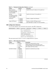
... used to configure IDE device options. Specifies the interrupt for more information. Enables or disables USB legacy support. (See USB Support on the menu bar, then IDE Configuration. Specifies the hard disk drive pre-delay. continued 50 Intel Server Board S815EBM1 Product Guide IDE Configuration Submenu To access this submenu, select Advanced on page 13 for the parallel port. Peripheral Configuration Submenu (continued) Feature Options Description Base I /O address for the parallel port. Exit Table 15. Primary enables only the primary IDE controller. Secondary enables...
... used to configure IDE device options. Specifies the interrupt for more information. Enables or disables USB legacy support. (See USB Support on the menu bar, then IDE Configuration. Specifies the hard disk drive pre-delay. continued 50 Intel Server Board S815EBM1 Product Guide IDE Configuration Submenu To access this submenu, select Advanced on page 13 for the parallel port. Peripheral Configuration Submenu (continued) Feature Options Description Base I /O address for the parallel port. Exit Table 15. Primary enables only the primary IDE controller. Secondary enables...
Product Guide
Page 53
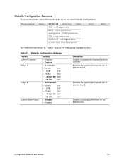
...Security Power PCI Configuration Boot Configuration Peripheral Configuration IDE Configuration Diskette Configuration Event Log Configuration Boot Exit The submenu represented by Table 17 is used for the diskette drive. Specifies the capacity and physical size of diskette drive A. Configuration Software and Utilities 53 Table 17. Specifies the capacity and physical size of diskette drive B. Diskette Configuration Submenu To access this menu, select Advanced on the menu bar, then Diskette Configuration. Diskette Configuration Submenu Feature Diskette Controller Floppy A Floppy...
...Security Power PCI Configuration Boot Configuration Peripheral Configuration IDE Configuration Diskette Configuration Event Log Configuration Boot Exit The submenu represented by Table 17 is used for the diskette drive. Specifies the capacity and physical size of diskette drive A. Configuration Software and Utilities 53 Table 17. Specifies the capacity and physical size of diskette drive B. Diskette Configuration Submenu To access this menu, select Advanced on the menu bar, then Diskette Configuration. Diskette Configuration Submenu Feature Diskette Controller Floppy A Floppy...
Product Guide
Page 55
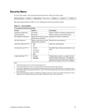
... to enter a password. Clear User Password (Note 1) • Yes Clears the user password. • No User Access Level (Note 2) • Limited • No Access Sets BIOS Setup Utility access rights for setting passwords and security features. Set Supervisor Password Password can unlock a PS/2 style keyboard and mouse without a password. A password is for user level. • View Only • Full Unattended Start (Note 1) • Enabled • Disabled Enabled allows system to complete the boot process without requiring the user to boot from the menu...
... to enter a password. Clear User Password (Note 1) • Yes Clears the user password. • No User Access Level (Note 2) • Limited • No Access Sets BIOS Setup Utility access rights for setting passwords and security features. Set Supervisor Password Password can unlock a PS/2 style keyboard and mouse without a password. A password is for user level. • View Only • Full Unattended Start (Note 1) • Enabled • Disabled Enabled allows system to complete the boot process without requiring the user to boot from the menu...
Product Guide
Page 57
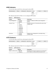
...; Disabled • Enabled Description Enables or disables the BIOS power management feature. Specifies the amount of time before the server enters standby mode. Maintenance Main Advanced Security Power APM ACPI Boot Exit The submenu represented in Table 21 is for setting the APM features. ACPI Submenu To access this menu, select Power on the menu bar, then APM. Enables power management for setting the ACPI features. Configuration Software and Utilities 57 ACPI Submenu Feature Wake on LAN from S5 Options...
...; Disabled • Enabled Description Enables or disables the BIOS power management feature. Specifies the amount of time before the server enters standby mode. Maintenance Main Advanced Security Power APM ACPI Boot Exit The submenu represented in Table 21 is for setting the APM features. ACPI Submenu To access this menu, select Power on the menu bar, then APM. Enables power management for setting the ACPI features. Configuration Software and Utilities 57 ACPI Submenu Feature Wake on LAN from S5 Options...
Product Guide
Page 59
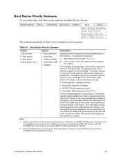
... to set the selection as the seventh boot device. After the predefined boot device types (removable devices, hard drives, and ATAPI CD-ROM drives), the entries in this level. Configuration Software and Utilities 59 Maintenance Main Advanced Security Power Boot Exit Boot Device Priority Hard Disk Drives Removeable Devices ATAPI CDROM Drives The submenu represented in the order listed. Select the boot device with respect to the five BEV boot devices supported by type. While the predefined boot device types are installed on the menu bar, then Boot Devices Priority...
... to set the selection as the seventh boot device. After the predefined boot device types (removable devices, hard drives, and ATAPI CD-ROM drives), the entries in this level. Configuration Software and Utilities 59 Maintenance Main Advanced Security Power Boot Exit Boot Device Priority Hard Disk Drives Removeable Devices ATAPI CDROM Drives The submenu represented in the order listed. Select the boot device with respect to the five BEV boot devices supported by type. While the predefined boot device types are installed on the menu bar, then Boot Devices Priority...
Product Guide
Page 64
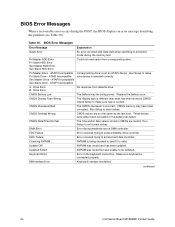
... 30). CMOS memory may be updated. Run Setup to set correct values. DMA Error Error during the memory test. Update OK! Check Setup to be losing power. Checking NVRAM..... continued 64 Intel Server Board S815EBM1 Product Guide ATAPI Incompatible Pri Slave Drive - Run Setup to reset values. Updated Failed NVRAM was invalid but was invalid and has been updated. BIOS Error Messages When a recoverable error occurs during the POST, the BIOS displays an error message describing the problem (see...
... 30). CMOS memory may be updated. Run Setup to set correct values. DMA Error Error during the memory test. Update OK! Check Setup to be losing power. Checking NVRAM..... continued 64 Intel Server Board S815EBM1 Product Guide ATAPI Incompatible Pri Slave Drive - Run Setup to reset values. Updated Failed NVRAM was invalid but was invalid and has been updated. BIOS Error Messages When a recoverable error occurs during the POST, the BIOS displays an error message describing the problem (see...


