Product Guide
Page 3
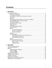
... ...7 Back Panel Connectors 8 Front Panel Connectors 9 Server Board Connector and Component Locations 10 Processors ...11 Memory ...11 Intel® 82815E Graphics Memory Controller Hub (GMCH 12 Intel® 82801BA I/O Controller Hub (ICH2 13 Firmware Hub (FWH 13 Input/Output (I/O) Controller 13 Real-Time Clock ...13 ...19 Memory ...20 DIMM Installation Guidelines 20 Installing DIMMs ...20 Removing DIMMs ...21 Installing the I/O Shield...22 Installing the Server Board 23 Installing a Processor ...24 Removing the Processor ...26 Installing a 1 GHz Processor Heatsink 27 Removing the 1 GHz...
... ...7 Back Panel Connectors 8 Front Panel Connectors 9 Server Board Connector and Component Locations 10 Processors ...11 Memory ...11 Intel® 82815E Graphics Memory Controller Hub (GMCH 12 Intel® 82801BA I/O Controller Hub (ICH2 13 Firmware Hub (FWH 13 Input/Output (I/O) Controller 13 Real-Time Clock ...13 ...19 Memory ...20 DIMM Installation Guidelines 20 Installing DIMMs ...20 Removing DIMMs ...21 Installing the I/O Shield...22 Installing the Server Board 23 Installing a Processor ...24 Removing the Processor ...26 Installing a 1 GHz Processor Heatsink 27 Removing the 1 GHz...
Product Guide
Page 5
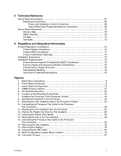
... Block Location 35 20. Installing the Processor in the Processor Socket 24 8. Connecting the Processor Fan Cable to the Processor 25 9. Location of the Mounting Screw Holes 23 7. 5 Technical Reference Server Board Connectors 67 Baseboard Connectors 68 Power and Hardware Control Connectors 68 Add-In Board and Peripheral Interface Connectors 69 Server Board Resources ...70 Memory Map ...70 DMA...
... Block Location 35 20. Installing the Processor in the Processor Socket 24 8. Connecting the Processor Fan Cable to the Processor 25 9. Location of the Mounting Screw Holes 23 7. 5 Technical Reference Server Board Connectors 67 Baseboard Connectors 68 Power and Hardware Control Connectors 68 Add-In Board and Peripheral Interface Connectors 69 Server Board Resources ...70 Memory Map ...70 DMA...
Product Guide
Page 6
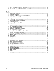
... 14. RJ-45 LAN Connector LEDs 16 5. Advanced Menu ...46 12. BIOS Error Messages 64 31. Interrupts ...72 vi Intel Server Board S815EBM1 Product Guide Maintenance Menu ...43 9. Hard Disk Drives Submenu 60 26. Supported Processors 11 3. Primary/Secondary IDE Master/Slave Submenus 51 17. System Memory Map 70 32. Jumper Settings for the BIOS...
... 14. RJ-45 LAN Connector LEDs 16 5. Advanced Menu ...46 12. BIOS Error Messages 64 31. Interrupts ...72 vi Intel Server Board S815EBM1 Product Guide Maintenance Menu ...43 9. Hard Disk Drives Submenu 60 26. Supported Processors 11 3. Primary/Secondary IDE Master/Slave Submenus 51 17. System Memory Map 70 32. Jumper Settings for the BIOS...

Product Guide
Page 7
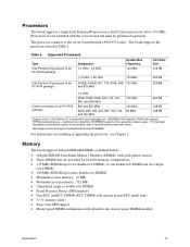
1 Description Server Board Features Table 1. Server Board Features Feature Processors Memory Chipset I/O Control Peripheral Interfaces SCSI LED Connector Expansion Capabilities BIOS Power Management Wake on LAN† Technology Form Factor Description Support for single row or double row DIMMs The S815EBM1 board includes the Intel® 815E Chipset, consisting of: • Intel® 82815 Graphics and Memory Controller Hub (GMCH...
1 Description Server Board Features Table 1. Server Board Features Feature Processors Memory Chipset I/O Control Peripheral Interfaces SCSI LED Connector Expansion Capabilities BIOS Power Management Wake on LAN† Technology Form Factor Description Support for single row or double row DIMMs The S815EBM1 board includes the Intel® 815E Chipset, consisting of: • Intel® 82815 Graphics and Memory Controller Hub (GMCH...
Product Guide
Page 11
...KB 256 KB 256 KB Celeron processor in Table 2. customers can determine S815EBM1 support at : http://support.intel.com/support/motherboards/server/S815EBM1/ For instructions on processor support for flexible memory configurations ...processor, see Chapter 2. Memory The board supports 168-pin SDRAM DIMMs as defined below: • 168-pin SDRAM Dual Inline Memory Modules (DIMMs) with the server board and must be purchased separately. Processors The board supports a single Intel Pentium III processor or Intel Celeron processor above 533 MHz. The processor connects to the Intel server board...
...KB 256 KB 256 KB Celeron processor in Table 2. customers can determine S815EBM1 support at : http://support.intel.com/support/motherboards/server/S815EBM1/ For instructions on processor support for flexible memory configurations ...processor, see Chapter 2. Memory The board supports 168-pin SDRAM DIMMs as defined below: • 168-pin SDRAM Dual Inline Memory Modules (DIMMs) with the server board and must be purchased separately. Processors The board supports a single Intel Pentium III processor or Intel Celeron processor above 533 MHz. The processor connects to the Intel server board...
Product Guide
Page 12
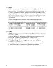
...processor (133 MHz) ...will operate at 100 MHz PC133 Memory Modules... ...will operate at 100 MHz ...will operate at 100 MHz ...will operate at 100 MHz ...will operate at 100 MHz. If more than four rows of SDRAM. • Support for ACPI Rev 2.0 and APM Rev 1.2 compliant power management. 12 Intel Server Board S815EBM1... Product Guide Intel® 82815E Graphics Memory Controller Hub (GMCH) The GMCH provides the following: • An integrated Synchronous...
...processor (133 MHz) ...will operate at 100 MHz PC133 Memory Modules... ...will operate at 100 MHz ...will operate at 100 MHz ...will operate at 100 MHz ...will operate at 100 MHz. If more than four rows of SDRAM. • Support for ACPI Rev 2.0 and APM Rev 1.2 compliant power management. 12 Intel Server Board S815EBM1... Product Guide Intel® 82815E Graphics Memory Controller Hub (GMCH) The GMCH provides the following: • An integrated Synchronous...
Product Guide
Page 14
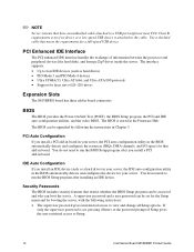
... Setup program can be set , pressing at the password prompt of information between the processor and peripheral devices like hard disks, and Iomega Zip† drives inside the server. The interface supports: • Up to Setup. 14 Intel Server Board S815EBM1 Product Guide PCI Auto Configuration If you install an IDE device (such as hard drives...
... Setup program can be set , pressing at the password prompt of information between the processor and peripheral devices like hard disks, and Iomega Zip† drives inside the server. The interface supports: • Up to Setup. 14 Intel Server Board S815EBM1 Product Guide PCI Auto Configuration If you install an IDE device (such as hard drives...
Product Guide
Page 24
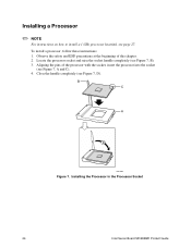
..., see Figure 7, A and C). 4. Observe the safety and ESD precautions at the beginning of the processor with the socket, insert the processor into the socket (see page 27. To install a processor, follow these instructions: 1. Installing the Processor in the Processor Socket 24 Intel Server Board S815EBM1 Product Guide B C A D OM11065 Figure 7. Aligning the pins of this chapter. 2. Close the handle completely...
..., see Figure 7, A and C). 4. Observe the safety and ESD precautions at the beginning of the processor with the socket, insert the processor into the socket (see page 27. To install a processor, follow these instructions: 1. Installing the Processor in the Processor Socket 24 Intel Server Board S815EBM1 Product Guide B C A D OM11065 Figure 7. Aligning the pins of this chapter. 2. Close the handle completely...
Product Guide
Page 25
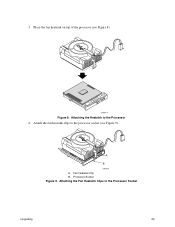
Attaching the Heatsink to the Processor Socket Upgrading 25 Processor Socket Figure 9. 5. A B OM09416 A. Attaching the Fan Heatsink Clips to the Processor 6. Attach the fan heatsink clips to the processor socket (see Figure 8). 2/)!% OM09415 Figure 8. Fan Heatsink Clip B. Place the fan heatsink on top of the processor (see Figure 9).
Attaching the Heatsink to the Processor Socket Upgrading 25 Processor Socket Figure 9. 5. A B OM09416 A. Attaching the Fan Heatsink Clips to the Processor 6. Attach the fan heatsink clips to the processor socket (see Figure 8). 2/)!% OM09415 Figure 8. Fan Heatsink Clip B. Place the fan heatsink on top of the processor (see Figure 9).
Product Guide
Page 26
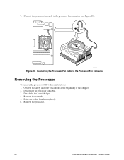
Connecting the Processor Fan Cable to the processor fan connector (see Figure 10). Remove the processor. 26 Intel Server Board S815EBM1 Product Guide 7. J1B1 J1B1 PGA370 OM11156 Figure 10. Disconnect the processor fan cable. 3. Connect the processor fan cable to the Processor Fan Connector Removing the Processor To remove the processor, follow these instructions: 1. Remove the heatsink. 5. Raise the socket handle completely. 6. Observe the safety and ESD precautions at the beginning of this chapter. 2. Detach the fan heatsink clips. 4.
Connecting the Processor Fan Cable to the processor fan connector (see Figure 10). Remove the processor. 26 Intel Server Board S815EBM1 Product Guide 7. J1B1 J1B1 PGA370 OM11156 Figure 10. Disconnect the processor fan cable. 3. Connect the processor fan cable to the Processor Fan Connector Removing the Processor To remove the processor, follow these instructions: 1. Remove the heatsink. 5. Raise the socket handle completely. 6. Observe the safety and ESD precautions at the beginning of this chapter. 2. Detach the fan heatsink clips. 4.

Product Guide
Page 27
... using the thermal solution provided with this server board warranty. Attaching the Fan Heatsink Over the Processor Upgrading 27 Attach the fan heatsink to the processor: 1. Installing a 1 GHz Processor Heatsink ✏ NOTES These instructions do NOT apply to : http://support.intel.com/support/motherboards/server/S815EBM1/ To install a 1 GHz processor, follow the instructions given on page 24, Figure 7. Follow the...
... using the thermal solution provided with this server board warranty. Attaching the Fan Heatsink Over the Processor Upgrading 27 Attach the fan heatsink to the processor: 1. Installing a 1 GHz Processor Heatsink ✏ NOTES These instructions do NOT apply to : http://support.intel.com/support/motherboards/server/S815EBM1/ To install a 1 GHz processor, follow the instructions given on page 24, Figure 7. Follow the...
Product Guide
Page 28
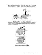
... 12 (A) shows the heatsink notch location. When properly aligned, each edge of the plastic clip should click into place. Lowering the Plastic Clip Handle 28 Intel Server Board S815EBM1 Product Guide A B OM11062 Figure 13. 2. Placing the Plastic Clip Over the Fan Heatsink 3. B C A OM11064 Figure 12. Hold the clip handle (see Figure 12, C). The inset... (see Figure 12, B) on the fan heatsink (see Figure 13, A) and very slowly lower the handle until the clip secures the fan heatsink to the processor socket.
... 12 (A) shows the heatsink notch location. When properly aligned, each edge of the plastic clip should click into place. Lowering the Plastic Clip Handle 28 Intel Server Board S815EBM1 Product Guide A B OM11062 Figure 13. 2. Placing the Plastic Clip Over the Fan Heatsink 3. B C A OM11064 Figure 12. Hold the clip handle (see Figure 12, C). The inset... (see Figure 12, B) on the fan heatsink (see Figure 13, A) and very slowly lower the handle until the clip secures the fan heatsink to the processor socket.
Product Guide
Page 29
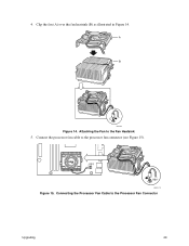
Connect the processor fan cable to the Processor Fan Connector Upgrading 29 J1B1 J1B1 OM11175 Figure 15. Clip the fan (A) over the fan heatsink (B) as illustrated in Figure 14. Connecting the Processor Fan Cable to the processor fan connector (see Figure 15). A B C OM11061 Figure 14. Attaching the Fan to the Fan Heatsink 5. 4.
Connect the processor fan cable to the Processor Fan Connector Upgrading 29 J1B1 J1B1 OM11175 Figure 15. Clip the fan (A) over the fan heatsink (B) as illustrated in Figure 14. Connecting the Processor Fan Cable to the processor fan connector (see Figure 15). A B C OM11061 Figure 14. Attaching the Fan to the Fan Heatsink 5. 4.
Product Guide
Page 30
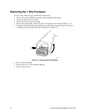
... the processor socket handle completely. 8. Removing the 1 GHz Processor To remove the 1 GHz processor, follow these instructions: 1. Observe the safety and ESD precautions at the beginning of the plastic clip (reversing the action shown in Figure 13, A). 5. Disengage the fan heatsink clip by pushing your thumb (see Figure 16). Remove the processor. 30 Intel Server Board S815EBM1 Product...
... the processor socket handle completely. 8. Removing the 1 GHz Processor To remove the 1 GHz processor, follow these instructions: 1. Observe the safety and ESD precautions at the beginning of the plastic clip (reversing the action shown in Figure 13, A). 5. Disengage the fan heatsink clip by pushing your thumb (see Figure 16). Remove the processor. 30 Intel Server Board S815EBM1 Product...
Product Guide
Page 43
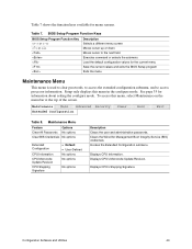
... Setup Program Function Keys BIOS Setup Program Function Key or or Description Selects a different menu screen Moves cursor up or down Moves cursor to access processor information. To access this menu in the configure mode. Displays CPU's Microcode Update Revision. Table 7. Table 7 shows the function keys available for the current menu...
... Setup Program Function Keys BIOS Setup Program Function Key or or Description Selects a different menu screen Moves cursor up or down Moves cursor to access processor information. To access this menu in the configure mode. Displays CPU's Microcode Update Revision. Table 7. Table 7 shows the function keys available for the current menu...
Product Guide
Page 44
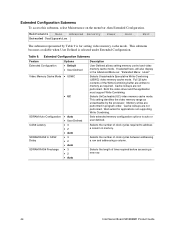
... allows setting memory control and video memory cache mode. Selects the number of time required before accessing a new row. 44 Intel Server Board S815EBM1 Product Guide Extended Configuration Submenu Feature Extended Configuration Options • Default • User-Defined Video Memory Cache Mode • ...range as : "Extended Menu: Used." Maintenance Main Advanced Security Extended Configuration Power Boot Exit The submenu represented by the processor. Table 9. Both the video driver and the application must support Write Combining. Cache lookups are performed in the Advanced...
... allows setting memory control and video memory cache mode. Selects the number of time required before accessing a new row. 44 Intel Server Board S815EBM1 Product Guide Extended Configuration Submenu Feature Extended Configuration Options • Default • User-Defined Video Memory Cache Mode • ...range as : "Extended Menu: Used." Maintenance Main Advanced Security Extended Configuration Power Boot Exit The submenu represented by the processor. Table 9. Both the video driver and the application must support Write Combining. Cache lookups are performed in the Advanced...
Product Guide
Page 45
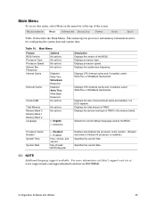
...and system time. Main Menu To access this menu, select Main on the menu bar at : www.support.intel.com/support/motherboards/server/S815EBM1. Displays processor type. Displays the total amount of RAM in the memory banks. Specifies the current date. ✏ NOTE Additional... language support available. This menu reports processor and memory information and is installed.) Specifies the current time. Displays the ...
...and system time. Main Menu To access this menu, select Main on the menu bar at : www.support.intel.com/support/motherboards/server/S815EBM1. Displays processor type. Displays the total amount of RAM in the memory banks. Specifies the current date. ✏ NOTE Additional... language support available. This menu reports processor and memory information and is installed.) Specifies the current time. Displays the ...
Product Guide
Page 63
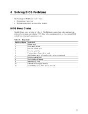
not used ) 8042 GateA20 cannot be reset First 64 K memory failure Timer not operational Processor failure (Reserved; Table 29. not used ) CMOS Shutdown register test error Invalid BIOS (such as, POST module not found) 63 4 Solving BIOS Problems The board reports POST errors in two ways: • By sounding a beep code • By...
not used ) 8042 GateA20 cannot be reset First 64 K memory failure Timer not operational Processor failure (Reserved; Table 29. not used ) CMOS Shutdown register test error Invalid BIOS (such as, POST module not found) 63 4 Solving BIOS Problems The board reports POST errors in two ways: • By sounding a beep code • By...
Product Guide
Page 68
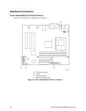
Processor fan (fan 1) B. Wake on LAN technology Figure 21. Chassis fan (fan 2) D. Power C. Baseboard Connectors Power and Hardware Control Connectors Figure 21 shows the power and hardware connectors. Power and Hardware Control Connectors 68 Intel Server Board S815EBM1 Product Guide A 1 1 1 1 10 11 20 D C B OM12209 A.
Processor fan (fan 1) B. Wake on LAN technology Figure 21. Chassis fan (fan 2) D. Power C. Baseboard Connectors Power and Hardware Control Connectors Figure 21 shows the power and hardware connectors. Power and Hardware Control Connectors 68 Intel Server Board S815EBM1 Product Guide A 1 1 1 1 10 11 20 D C B OM12209 A.
Product Guide
Page 75
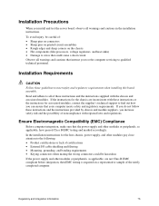
...for the chassis are not Class B EMC compliant before integration, then EMC testing is required on the chassis • Hot components (like processors, voltage regulators, and heat sinks) • Damage to wires that could be careful of these instructions and the instructions supplied with regional ...cause a short circuit Observe all warnings and cautions that instruct you to refer computer servicing to find out how you install and test the server board, observe all of : • Sharp pins on connectors • Sharp pins on printed circuit assemblies • Rough edges and sharp ...
...for the chassis are not Class B EMC compliant before integration, then EMC testing is required on the chassis • Hot components (like processors, voltage regulators, and heat sinks) • Damage to wires that could be careful of these instructions and the instructions supplied with regional ...cause a short circuit Observe all warnings and cautions that instruct you to refer computer servicing to find out how you install and test the server board, observe all of : • Sharp pins on connectors • Sharp pins on printed circuit assemblies • Rough edges and sharp ...


