User Guide
Page 6
... tested with this product Use this Document or Software Technical Product Specification Intel® Server Board S5500BC Quick Start User's Guide in the product box Spares and Configuration Guide Tested Hardware and Operating System List Reference Chassis List Supported Processors Supported Memory vi Intel® Server Board S5500BC User's Guide For this information or software For in-depth technical information...
... tested with this product Use this Document or Software Technical Product Specification Intel® Server Board S5500BC Quick Start User's Guide in the product box Spares and Configuration Guide Tested Hardware and Operating System List Reference Chassis List Supported Processors Supported Memory vi Intel® Server Board S5500BC User's Guide For this information or software For in-depth technical information...
User Guide
Page 13
... Figure 10. Channel Slots Configuration 11 Figure 7. List of Figures Figure 1. DIMM Configuration Diagram 10 Figure 6. Replacing the Backup Battery 23 Figure 18. CMOS Recovery Jumper 31 Figure 21. BIOS Recovery Jumper 29 Figure 19. Remove the Processor Protective Cover 16 Figure 12. Diagnostic LED Placement Diagram 51 Intel® Server Board S5500BC User's Guide xiii
... Figure 10. Channel Slots Configuration 11 Figure 7. List of Figures Figure 1. DIMM Configuration Diagram 10 Figure 6. Replacing the Backup Battery 23 Figure 18. CMOS Recovery Jumper 31 Figure 21. BIOS Recovery Jumper 29 Figure 19. Remove the Processor Protective Cover 16 Figure 12. Diagnostic LED Placement Diagram 51 Intel® Server Board S5500BC User's Guide xiii
User Guide
Page 15
...Component Locations 3 Configuration Jumpers...5 Back Panel Connectors ...7 RAID Support...8 Hardware Requirements 9 Optional Hardware...12 Chapter 2: Hardware Installations and Upgrades 13 Before You Begin...13 Tools and Supplies Needed 13 Installing and Removing Memory 13 Installing ...Server Utilities 25 Using the BIOS Setup Utility 25 Starting Setup...25 If You Cannot Access Setup 25 Setup Menus ...25 Upgrading the BIOS...27 Preparing for the Upgrade 27 BIOS Recovery Mode and BIOS Flash Update 28 Recovering the BIOS ...28 Clearing the Password...30 Intel® Server Board S5500BC...
...Component Locations 3 Configuration Jumpers...5 Back Panel Connectors ...7 RAID Support...8 Hardware Requirements 9 Optional Hardware...12 Chapter 2: Hardware Installations and Upgrades 13 Before You Begin...13 Tools and Supplies Needed 13 Installing and Removing Memory 13 Installing ...Server Utilities 25 Using the BIOS Setup Utility 25 Starting Setup...25 If You Cannot Access Setup 25 Setup Menus ...25 Upgrading the BIOS...27 Preparing for the Upgrade 27 BIOS Recovery Mode and BIOS Flash Update 28 Recovering the BIOS ...28 Clearing the Password...30 Intel® Server Board S5500BC...
User Guide
Page 30
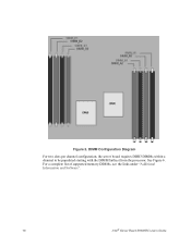
See Figure 6. For a complete list of supported memory DIMMs, see the links under "Additional Information and Software". 10 Intel® Server Board S5500BC User's Guide DIMM Configuration Diagram For two slots per channel configuration, the server board requires DDR3 DIMMs within a channel to be populated starting with the DIMM farthest from the processor. Figure 5.
See Figure 6. For a complete list of supported memory DIMMs, see the links under "Additional Information and Software". 10 Intel® Server Board S5500BC User's Guide DIMM Configuration Diagram For two slots per channel configuration, the server board requires DDR3 DIMMs within a channel to be populated starting with the DIMM farthest from the processor. Figure 5.
User Guide
Page 31
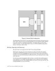
.... Channel Slots Configuration The Independent Channel Mode is the default Maximum Performance Mode preferred for mirroring. Memory Sparing and Mirroring The spare mode is one time. With memory mirroring, the system maintains two copies of two DIMMs installed. In a mirrored system, the maximum usable memory is not supported by the Intel® Server Board S5500BC. Intel® Server Board S5500BC User's Guide...
.... Channel Slots Configuration The Independent Channel Mode is the default Maximum Performance Mode preferred for mirroring. Memory Sparing and Mirroring The spare mode is one time. With memory mirroring, the system maintains two copies of two DIMMs installed. In a mirrored system, the maximum usable memory is not supported by the Intel® Server Board S5500BC. Intel® Server Board S5500BC User's Guide...
User Guide
Page 33
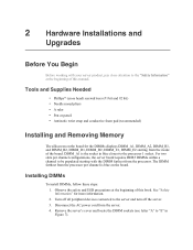
... #2 bit) • Needle nosed pliers • A ruler • Pen or pencil • Antistatic wrist strap and conductive foam pad (recommended) Installing and Removing Memory The silkscreen on the board. The DIMM farthest from the processor per channel configurations, the server board requires DDR3 DIMMs within a channel to the "Safety Information" at the beginning of the...
... #2 bit) • Needle nosed pliers • A ruler • Pen or pencil • Antistatic wrist strap and conductive foam pad (recommended) Installing and Removing Memory The silkscreen on the board. The DIMM farthest from the processor per channel configurations, the server board requires DDR3 DIMMs within a channel to the "Safety Information" at the beginning of the...
User Guide
Page 45
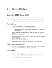
...SETUP In a third condition, when CMOS/NVRAM is corrupted, you use to change these parameters. For instructions on the server board to display automatically configured information, each feature is inaccessible. If a value cannot be changed for any reason, the feature's value field is ... Setup under several conditions: • When you turn on the server, after POST completes the memory test. • When you might need to the Technical Product Specification where you can change server configuration defaults. Refer to "Additional Information and Software" for those features ...
...SETUP In a third condition, when CMOS/NVRAM is corrupted, you use to change these parameters. For instructions on the server board to display automatically configured information, each feature is inaccessible. If a value cannot be changed for any reason, the feature's value field is ... Setup under several conditions: • When you turn on the server, after POST completes the memory test. • When you might need to the Technical Product Specification where you can change server configuration defaults. Refer to "Additional Information and Software" for those features ...
User Guide
Page 47
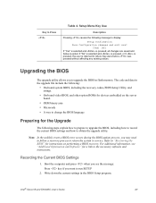
... BIOS, including how to record the current BIOS settings and how to display: Setup Confirmation Save Configuration changes and exit now? [Yes] [No] If "Yes" is selected and is pressed, ...all changes are saved and Setup is returned to upgrade the BIOS in flash memory. The code and data in the BIOS Setup program. Note: In the unlikely event a BIOS ...for a link to Press Table 4. Upgrading the BIOS The upgrade utility allows you want to service. Intel® Server Board S5500BC User's Guide 27 If "No" is selected and is pressed, or if is pressed, the user ...
... BIOS, including how to record the current BIOS settings and how to display: Setup Confirmation Save Configuration changes and exit now? [Yes] [No] If "Yes" is selected and is pressed, ...all changes are saved and Setup is returned to upgrade the BIOS in flash memory. The code and data in the BIOS Setup program. Note: In the unlikely event a BIOS ...for a link to Press Table 4. Upgrading the BIOS The upgrade utility allows you want to service. Intel® Server Board S5500BC User's Guide 27 If "No" is selected and is pressed, or if is pressed, the user ...
User Guide
Page 54
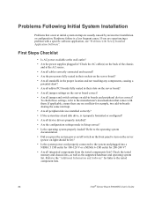
...them. Check the tested memory and chassis lists, as well as the supported hardware and operating system list. If applicable, ensure there are no conflicts-for example, two add-in their slots on the server board? • Are all jumper settings on the server board correct? • ... failure is it properly formatted or configured? • Are all integrated components from the tested components lists? If you press the system power on/off switch on the front panel to the tested component lists. 34 Intel® Server Board S5500BC User's Guide Problems Following Initial System...
...them. Check the tested memory and chassis lists, as well as the supported hardware and operating system list. If applicable, ensure there are no conflicts-for example, two add-in their slots on the server board? • Are all jumper settings on the server board correct? • ... failure is it properly formatted or configured? • Are all integrated components from the tested components lists? If you press the system power on/off switch on the front panel to the tested component lists. 34 Intel® Server Board S5500BC User's Guide Problems Following Initial System...
User Guide
Page 73
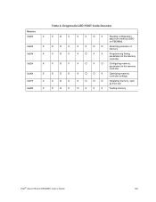
... X 0x24h X 0x25h X 0x26h X 0x27h X 0x28h X Table 8. Diagnostic LED POST Code Decoder X O X X O X X O X X O X X O X X O X X O X X X O X Reading configuration data from memory (SPD on FBDIMM) X X O O Detecting presence of memory X O X X Programming timing parameters in the memory controller X O X O Configuring memory parameters in the memory controller X O O X Optimizing memory controller settings X O O O Initializing memory, such as ECC init O X X X Testing memory Intel® Server Board S5500BC User's Guide 53
... X 0x24h X 0x25h X 0x26h X 0x27h X 0x28h X Table 8. Diagnostic LED POST Code Decoder X O X X O X X O X X O X X O X X O X X O X X X O X Reading configuration data from memory (SPD on FBDIMM) X X O O Detecting presence of memory X O X X Programming timing parameters in the memory controller X O X O Configuring memory parameters in the memory controller X O O X Optimizing memory controller settings X O O O Initializing memory, such as ECC init O X X X Testing memory Intel® Server Board S5500BC User's Guide 53

User Guide
Page 77
... been called) Pre-EFI Initialization Module (PEIM) / Recovery 0x30h X X O O X X X X Crisis recovery has been initiated because of a user request Intel® Server Board S5500BC User's Guide 57 Table 8. Diagnostic LED POST Code Decoder 0xE2h O O O X X X O X Initial memory found, configured, and installed correctly 0xE3h O O O X X X O O Reserved for initialization module use (PEIM) Driver Execution Environment (DXE) Core (not accompanied by a beep...
... been called) Pre-EFI Initialization Module (PEIM) / Recovery 0x30h X X O O X X X X Crisis recovery has been initiated because of a user request Intel® Server Board S5500BC User's Guide 57 Table 8. Diagnostic LED POST Code Decoder 0xE2h O O O X X X O X Initial memory found, configured, and installed correctly 0xE3h O O O X X X O O Reserved for initialization module use (PEIM) Driver Execution Environment (DXE) Core (not accompanied by a beep...


