
User Guide
Page 7
... available in the Intel® S5000 Server Board Family Data Sheet. Manual Organization Chapter 1 provides a brief overview of the product, and product diagrams to help you identify components and their locations. Use this manual, see http://support.intel.com/ support/motherboards/server/S5000VSA/. In this chapter, you will find a list of the server board features, photos of the Intel® Server Board S5000VSA.
... available in the Intel® S5000 Server Board Family Data Sheet. Manual Organization Chapter 1 provides a brief overview of the product, and product diagrams to help you identify components and their locations. Use this manual, see http://support.intel.com/ support/motherboards/server/S5000VSA/. In this chapter, you will find a list of the server board features, photos of the Intel® Server Board S5000VSA.
User Guide
Page 11
...importantes xiii Warnings ...xv Chapter 1: Server Board Features 1 RAID Support ...3 SATA Server Board ...3 SAS Server Board ...4 Connector and Component Locations 5 Configuration Jumpers ...7 Back Panel Connectors ...8 Hardware Requirements ...9 Processor ...9 Memory ...9 Power Supply ...9 Optional Hardware ...10 Hard Disk Drives ...10 Intel® Local Control Panel 10 Chapter 2: Server Utilities 11 Using the BIOS Setup ... ...15 Chapter 3: Hardware Installations and Upgrades 17 Before You Begin ...17 Tools and Supplies Needed 17 Intel® Server Board S5000VSA User's Guide xi
...importantes xiii Warnings ...xv Chapter 1: Server Board Features 1 RAID Support ...3 SATA Server Board ...3 SAS Server Board ...4 Connector and Component Locations 5 Configuration Jumpers ...7 Back Panel Connectors ...8 Hardware Requirements ...9 Processor ...9 Memory ...9 Power Supply ...9 Optional Hardware ...10 Hard Disk Drives ...10 Intel® Local Control Panel 10 Chapter 2: Server Utilities 11 Using the BIOS Setup ... ...15 Chapter 3: Hardware Installations and Upgrades 17 Before You Begin ...17 Tools and Supplies Needed 17 Intel® Server Board S5000VSA User's Guide xi
User Guide
Page 17
... Component Locations 6 Figure 3. Back Panel Connectors 8 Figure 5. Removing the Protective Socket Cover 21 Figure 13. Replacing the Backup Battery (S5000VSASATA/S5000VSASATAR shown) ....... 25 Intel® Server Board S5000VSA User's Guide xvii List of Figures Figure 1. Lifting the Socket Handle 20 Figure 9. Installing the Processor 21 Figure 12. Installing ... 16 Figure 7. Removing the Shipping Cover 21 Figure 11. Configuration Jumper Descriptions 7 Figure 4. Installing Memory (S5000VSASATA/S5000VSASATAR shown 18 Figure 8. Intel® Server Board S5000VSA 1 Figure 2.
... Component Locations 6 Figure 3. Back Panel Connectors 8 Figure 5. Removing the Protective Socket Cover 21 Figure 13. Replacing the Backup Battery (S5000VSASATA/S5000VSASATAR shown) ....... 25 Intel® Server Board S5000VSA User's Guide xvii List of Figures Figure 1. Lifting the Socket Handle 20 Figure 9. Installing the Processor 21 Figure 12. Installing ... 16 Figure 7. Removing the Shipping Cover 21 Figure 11. Configuration Jumper Descriptions 7 Figure 4. Installing Memory (S5000VSASATA/S5000VSASATAR shown 18 Figure 8. Intel® Server Board S5000VSA 1 Figure 2.
User Guide
Page 20
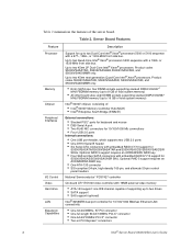
...-bit/100MHz PCI-X* connector • Two x4 PCI Express* connectors 2 Intel® Server Board S5000VSA User's Guide Up to two 45nm 2P Dual-Core Intel® Xeon® processors. Up to two 45nm next generation Quad-Core Intel® Xeon® processors. or 1333-MHz front side bus. Up to... • One ATA-133 connector • SSI-compliant 34-pin, high-density 100-pin, and alternate 50-pin control panel headers National Semiconductor* PC87427 controller On-board ATI* ES1000 video controller with 16MB external video memory • ATA-133 support: one IDE channel capable of : •...
...-bit/100MHz PCI-X* connector • Two x4 PCI Express* connectors 2 Intel® Server Board S5000VSA User's Guide Up to two 45nm 2P Dual-Core Intel® Xeon® processors. Up to two 45nm next generation Quad-Core Intel® Xeon® processors. or 1333-MHz front side bus. Up to... • One ATA-133 connector • SSI-compliant 34-pin, high-density 100-pin, and alternate 50-pin control panel headers National Semiconductor* PC87427 controller On-board ATI* ES1000 video controller with 16MB external video memory • ATA-133 support: one IDE channel capable of : •...
User Guide
Page 25
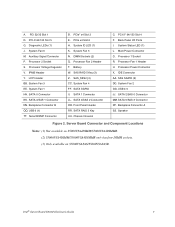
... 5 Key (3) Z. SATA SGPIO II. Front Panel Header RR. Chassis Intrusion C. Server Board Connector and Component Locations Notes: (1) Not available on S5000VSA4DIMM/S5000VSA4DIMMR. (2) S5000VSA4DIMM/S5000VSA4DIMMR only has four DIMM sockets. (3) Only available on S5000VSASAS/S5000VSASASR. Intel® Server Board S5000VSA User's Guide 7 Auxiliary Signal Connector P. System Fan...SAS_SES2 (3) CC. SATA 1 Connector LL. SATA 4/SAS 2 Connector OO. SATA RAID 5 Key UU. Back Panel I/O Ports I. SAS SGPIO (3) DD. System Fan 2 GG. Backplane Connector A SS. Speaker Figure 2.
... 5 Key (3) Z. SATA SGPIO II. Front Panel Header RR. Chassis Intrusion C. Server Board Connector and Component Locations Notes: (1) Not available on S5000VSA4DIMM/S5000VSA4DIMMR. (2) S5000VSA4DIMM/S5000VSA4DIMMR only has four DIMM sockets. (3) Only available on S5000VSASAS/S5000VSASASR. Intel® Server Board S5000VSA User's Guide 7 Auxiliary Signal Connector P. System Fan...SAS_SES2 (3) CC. SATA 1 Connector LL. SATA 4/SAS 2 Connector OO. SATA RAID 5 Key UU. Back Panel I/O Ports I. SAS SGPIO (3) DD. System Fan 2 GG. Backplane Connector A SS. Speaker Figure 2.

User Guide
Page 27
... (if left of each NIC provide the following information. NIC 1 (10/100/1000 Mb) E. Back Panel Connectors E AF000184 The NIC LEDs at the right and left LED is on or blinking) 100 Mbps connection 1000 Mbps connection Intel® Server Board S5000VSA User's Guide 9 NIC 2 (10/100/1000 Mb) F. USB 0-1 H. Serial Port B D. Table 3. USB 2-3 G. Back...
... (if left of each NIC provide the following information. NIC 1 (10/100/1000 Mb) E. Back Panel Connectors E AF000184 The NIC LEDs at the right and left LED is on or blinking) 100 Mbps connection 1000 Mbps connection Intel® Server Board S5000VSA User's Guide 9 NIC 2 (10/100/1000 Mb) F. USB 0-1 H. Serial Port B D. Table 3. USB 2-3 G. Back...

User Guide
Page 29
... enhanced system control by utilizing a LCD display, which provides additional controls and indicators beyond the standard control panel. Intel® Server Board S5000VSA User's Guide 11 Power Supply A minimum of the server board. IDE devices can be connected to the standard IDE connector located near the front left side of 550 Watts is required. The IDE connection...
... enhanced system control by utilizing a LCD display, which provides additional controls and indicators beyond the standard control panel. Intel® Server Board S5000VSA User's Guide 11 Power Supply A minimum of the server board. IDE devices can be connected to the standard IDE connector located near the front left side of 550 Watts is required. The IDE connection...

User Guide
Page 60
...; Is the operating system properly loaded? To check these settings, refer to the system and plugged into a properly grounded AC outlet. 42 Intel® Server Board S5000VSA User's Guide See the operating system documentation. • Did you press the system power on light should be lit)? • Is the...on add-in boards and peripheral devices correct? Check the tested memory, and chassis lists, as well as the supported hardware and operating system list. See "Additional Information and Software" for the keyboard and the video monitor. 2. Turn off switch on the front panel to the ...
...; Is the operating system properly loaded? To check these settings, refer to the system and plugged into a properly grounded AC outlet. 42 Intel® Server Board S5000VSA User's Guide See the operating system documentation. • Did you press the system power on light should be lit)? • Is the...on add-in boards and peripheral devices correct? Check the tested memory, and chassis lists, as well as the supported hardware and operating system list. See "Additional Information and Software" for the keyboard and the video monitor. 2. Turn off switch on the front panel to the ...
User Guide
Page 62
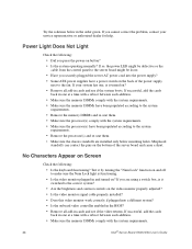
...the system requirements. • Remove the processor(s) and re-seat them . • Make sure the processor(s) comply with the system requirements. 44 Intel® Server Board S5000VSA User's Guide If successful, add the cards back in one at a time with a reboot between each addition. • Make sure the memory ...the order given. If so, the power LED might be defective or the cable from the control panel to the fan. Misplaced standoffs can contact the pins on the back of the server board and cause a short. No Characters Appear on the video monitor properly adjusted? • Is ...
...the system requirements. • Remove the processor(s) and re-seat them . • Make sure the processor(s) comply with the system requirements. 44 Intel® Server Board S5000VSA User's Guide If successful, add the cards back in one at a time with a reboot between each addition. • Make sure the memory ...the order given. If so, the power LED might be defective or the cable from the control panel to the fan. Misplaced standoffs can contact the pins on the back of the server board and cause a short. No Characters Appear on the video monitor properly adjusted? • Is ...

User Guide
Page 63
... the beep code you hear. Characters Are Distorted or Incorrect Check the following : • Is the power-on the video monitor? Intel® Server Board S5000VSA User's Guide 45 • Make sure the memory DIMMs have been populated according to the system requirements. • Remove the memory ...Are the brightness and contrast controls properly adjusted on light lit? Use the server management subsystem to a fan that the video controller board is one or more of these LEDs lit? • Are any other control panel LEDs lit? • Have any of possible system component failure. If...
... the beep code you hear. Characters Are Distorted or Incorrect Check the following : • Is the power-on the video monitor? Intel® Server Board S5000VSA User's Guide 45 • Make sure the memory DIMMs have been populated according to the system requirements. • Remove the memory ...Are the brightness and contrast controls properly adjusted on light lit? Use the server management subsystem to a fan that the video controller board is one or more of these LEDs lit? • Are any other control panel LEDs lit? • Have any of possible system component failure. If...

User Guide
Page 64
... and signal cables properly installed? • Are all relevant switches and jumpers on changing interrupts. 46 Intel® Server Board S5000VSA User's Guide Problems with Network The server hangs when the drivers are loaded • Certain drivers may be necessary to alter settings so that ...the NIC connectors. • Are the fan power connectors properly connected to the server board? • Is the cable from the control panel board connected to the both the control panel board and to the server board? • Are the power supply cables properly connected to the correct connector at...
... and signal cables properly installed? • Are all relevant switches and jumpers on changing interrupts. 46 Intel® Server Board S5000VSA User's Guide Problems with Network The server hangs when the drivers are loaded • Certain drivers may be necessary to alter settings so that ...the NIC connectors. • Are the fan power connectors properly connected to the server board? • Is the cable from the control panel board connected to the both the control panel board and to the server board? • Are the power supply cables properly connected to the correct connector at...

User Guide
Page 65
... adapter supports shared interrupts. See the software documentation. • Make sure the software is properly installed and configured for the software. Intel® Server Board S5000VSA User's Guide 47 See "Additional Information and Software" for a link to the current version. • Make sure the other software...may be sent to command the system to the software, not the server hardware. Before installing a PCI card, you should always: • Turn off the server power by using the power button on the front panel. Check the following: • Make sure the system meets the...
... adapter supports shared interrupts. See the software documentation. • Make sure the software is properly installed and configured for the software. Intel® Server Board S5000VSA User's Guide 47 See "Additional Information and Software" for a link to the current version. • Make sure the other software...may be sent to command the system to the software, not the server hardware. Before installing a PCI card, you should always: • Turn off the server power by using the power button on the front panel. Check the following: • Make sure the system meets the...

User Guide
Page 67
LED Information The Intel® Server Board S5000VSA includes LEDs that can aid in server identification from the back panel System Fault Visible fault warning Front control panel and board rear left corner Control panel and board rear left corner Blue Green or Amber Notes Off = Power is off . A table of these LEDs with SCSI or SATA drives, make sure the...
LED Information The Intel® Server Board S5000VSA includes LEDs that can aid in server identification from the back panel System Fault Visible fault warning Front control panel and board rear left corner Control panel and board rear left corner Blue Green or Amber Notes Off = Power is off . A table of these LEDs with SCSI or SATA drives, make sure the...

User Guide
Page 71
Peripheral Add-in Video NIC On-Board NIC1 On-Board NIC2 Description Hard Drive Information Drive Type (SATA, SAS, etc.) Make/Model Driver Revision IRQ I/O Base FW Address Revision Hot-swap or Fixed IRQ FW Revision Management Information On-Board Platform Instrumentation only Intel® System Management Control Panel Information Standard Control Panel Intel® Local Control Panel Intel® Server Board S5000VSA User's Guide 53
Peripheral Add-in Video NIC On-Board NIC1 On-Board NIC2 Description Hard Drive Information Drive Type (SATA, SAS, etc.) Make/Model Driver Revision IRQ I/O Base FW Address Revision Hot-swap or Fixed IRQ FW Revision Management Information On-Board Platform Instrumentation only Intel® System Management Control Panel Information Standard Control Panel Intel® Local Control Panel Intel® Server Board S5000VSA User's Guide 53


