
User Guide
Page 11
... Chapter 1: Server Board Features 1 Connector and Header Locations 5 Configuration Jumpers ...7 Intel® Light-Guided Diagnostics 9 Back Panel Features ...12 RAID Support ...13 SATA Server Board ...13 SAS Server Board ...14 ROMB Server Board ...15 Hardware...Intel® Remote Management Module / Intel® Remote Management Module 2 and RMM NIC / RMM2 NIC 20 Intel® Local Control Panel 20 Chapter 2: System Utilities 21 Using the BIOS Setup Utility 21 Starting Setup ...21 If You Cannot Access Setup 21 Setup Menus ...22 Upgrading the BIOS ...23 Intel® Server Board S5000PSL...
... Chapter 1: Server Board Features 1 Connector and Header Locations 5 Configuration Jumpers ...7 Intel® Light-Guided Diagnostics 9 Back Panel Features ...12 RAID Support ...13 SATA Server Board ...13 SAS Server Board ...14 ROMB Server Board ...15 Hardware...Intel® Remote Management Module / Intel® Remote Management Module 2 and RMM NIC / RMM2 NIC 20 Intel® Local Control Panel 20 Chapter 2: System Utilities 21 Using the BIOS Setup Utility 21 Starting Setup ...21 If You Cannot Access Setup 21 Setup Menus ...22 Upgrading the BIOS ...23 Intel® Server Board S5000PSL...

User Guide
Page 15
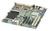
Intel® Server Board S5000PSL 1 Figure 2. Server Board Connector and Component Locations 6 Figure 3. Password Clear Jumper in Force Lower Bank Position 25 Figure 7. Locating DIMM Sockets 30 Figure 10. Opening Load... Active Heatsink Cable Connections 39 Figure 18. Locating and Removing the CMOS Battery 44 Intel® Server Board S5000PSL xv Removing Processor from Load Plate 36 Figure 15. Installing Protective Cover onto Load Plate 42 Figure 22. Back Panel Connectors and LEDs 12 Figure 5. BIOS Bank Select Jumper in Clear Password Position 26 Figure...
Intel® Server Board S5000PSL 1 Figure 2. Server Board Connector and Component Locations 6 Figure 3. Password Clear Jumper in Force Lower Bank Position 25 Figure 7. Locating DIMM Sockets 30 Figure 10. Opening Load... Active Heatsink Cable Connections 39 Figure 18. Locating and Removing the CMOS Battery 44 Intel® Server Board S5000PSL xv Removing Processor from Load Plate 36 Figure 15. Installing Protective Cover onto Load Plate 42 Figure 22. Back Panel Connectors and LEDs 12 Figure 5. BIOS Bank Select Jumper in Clear Password Position 26 Figure...

User Guide
Page 21
... support: One IDE channel that supports a peripheral, such as a floppy drive • One DH10 serial port B header • One of the Intel® RAID Activation Key and a RAID DIMM adds intelligent RAID 0, 1, 5, 10, and 50. • One ATA-100 40-pin connector • One SSI-compliant 24-pin front control panel header Intel® Server Board S5000PSL 3
... support: One IDE channel that supports a peripheral, such as a floppy drive • One DH10 serial port B header • One of the Intel® RAID Activation Key and a RAID DIMM adds intelligent RAID 0, 1, 5, 10, and 50. • One ATA-100 40-pin connector • One SSI-compliant 24-pin front control panel header Intel® Server Board S5000PSL 3

User Guide
Page 22
... installed, hardware RAID support is available for Intel® System Management software • Intel® Light-Guided Diagnostics on field replaceable units 4 Intel® Server Board S5000PSL Uses specially keyed PCI Express slot, add-in...connectors • Four 6-pin front fan connectors • Two 4-pin rear fan connectors • Support for the Intel® Local Control Panel (optional component sold separately) • Support for Intel® Remote Management Module 2 and RMM2 NIC (optional component sold separately) • Support for RAID 0, 1, 5, 10, and 50. Server Board...
... installed, hardware RAID support is available for Intel® System Management software • Intel® Light-Guided Diagnostics on field replaceable units 4 Intel® Server Board S5000PSL Uses specially keyed PCI Express slot, add-in...connectors • Four 6-pin front fan connectors • Two 4-pin rear fan connectors • Support for the Intel® Local Control Panel (optional component sold separately) • Support for Intel® Remote Management Module 2 and RMM2 NIC (optional component sold separately) • Support for RAID 0, 1, 5, 10, and 50. Server Board...

User Guide
Page 24
... 4 header W. System fan 1 header AA. SATA 2 or SAS 0 (SAS 0 is available only on page 12) M. Front control panel header QQ. Server Board Connector and Component Locations 6 Intel® Server Board S5000PSL PCI Express x8 slot 5 G. RMM connector (connector for Intel® Remote Management Module) K. Back panel I . System fan 6 header N. SATA 3 or SAS 1 (SAS 1 is available only on page 12) L. Serial B / emergency management...
... 4 header W. System fan 1 header AA. SATA 2 or SAS 0 (SAS 0 is available only on page 12) M. Front control panel header QQ. Server Board Connector and Component Locations 6 Intel® Server Board S5000PSL PCI Express x8 slot 5 G. RMM connector (connector for Intel® Remote Management Module) K. Back panel I . System fan 6 header N. SATA 3 or SAS 1 (SAS 1 is available only on page 12) L. Serial B / emergency management...

User Guide
Page 30
... / receive activity is on page 9. C EG AB D F H I . NIC 2 (top), two USB (bottom) Figure 4. Back Panel Connectors and LEDs The NIC LEDs at the right and left LED is occurring 10 Mbps connection (if left of each NIC provide the following information...E. Bit 1 LED (POST LED) G. For information about the LEDs, see "Intel® Light-Guided Diagnostics" on or blinking) 100 Mbps connection 1000 Mbps connection 12 Intel® Server Board S5000PSL Back Panel Features The diagram and table show the back panel connectors and LEDs. Bit 2 LED (POST LED) F. NIC1 (top), two USB (...
... / receive activity is on page 9. C EG AB D F H I . NIC 2 (top), two USB (bottom) Figure 4. Back Panel Connectors and LEDs The NIC LEDs at the right and left LED is occurring 10 Mbps connection (if left of each NIC provide the following information...E. Bit 1 LED (POST LED) G. For information about the LEDs, see "Intel® Light-Guided Diagnostics" on or blinking) 100 Mbps connection 1000 Mbps connection 12 Intel® Server Board S5000PSL Back Panel Features The diagram and table show the back panel connectors and LEDs. Bit 2 LED (POST LED) F. NIC1 (top), two USB (...

User Guide
Page 38
...remote control. Intel® Remote Management Module / Intel® Remote Management Module 2 and RMM NIC / RMM2 NIC The Intel® Remote Management Module / Intel® Remote Management Module 2 and the RMM NIC / RMM2 NIC plug into connectors on the ...server board and act as components of the server board, not as its own CD-ROM drive. Intel® Local Control Panel The Intel® Local Control Panel provides enhanced system control by utilizing a LCD display, which provides additional controls and indicators beyond the standard control panel. 20 Intel® Server Board S5000PSL...
...remote control. Intel® Remote Management Module / Intel® Remote Management Module 2 and RMM NIC / RMM2 NIC The Intel® Remote Management Module / Intel® Remote Management Module 2 and the RMM NIC / RMM2 NIC plug into connectors on the ...server board and act as components of the server board, not as its own CD-ROM drive. Intel® Local Control Panel The Intel® Local Control Panel provides enhanced system control by utilizing a LCD display, which provides additional controls and indicators beyond the standard control panel. 20 Intel® Server Board S5000PSL...
User Guide
Page 68
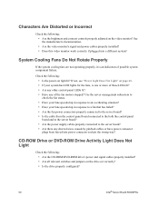
... fans speeded up in response to a fan that has failed? • Are the fan power connectors properly connected to the server board? • Is the cable from the control panel board connected to the both the control panel board and to the server board? • Are the power supply cables properly connected to an overheating situation? • Have your... Incorrect Check the following: • Are the brightness and contrast controls properly adjusted on the drive set correctly? • Is the drive properly configured? 50 Intel® Server Board S5000PSL
... fans speeded up in response to a fan that has failed? • Are the fan power connectors properly connected to the server board? • Is the cable from the control panel board connected to the both the control panel board and to the server board? • Are the power supply cables properly connected to an overheating situation? • Have your... Incorrect Check the following: • Are the brightness and contrast controls properly adjusted on the drive set correctly? • Is the drive properly configured? 50 Intel® Server Board S5000PSL

User Guide
Page 69
.... • Make sure the correct networking software is installed. • If you are using the correct and the current drivers. Intel® Server Board S5000PSL 51 Diagnostics pass but the connection fails • Make sure the network cable is securely attached. • Make sure you specify...CFG file. • The controller stopped working when an add-in adapter. Cannot Connect to a Server • Make sure the network cable is securely attached to the correct connector at the system back panel. • Try a different network cable. • Make sure you are directly connecting two...
.... • Make sure the correct networking software is installed. • If you are using the correct and the current drivers. Intel® Server Board S5000PSL 51 Diagnostics pass but the connection fails • Make sure the network cable is securely attached. • Make sure you specify...CFG file. • The controller stopped working when an add-in adapter. Cannot Connect to a Server • Make sure the network cable is securely attached to the correct connector at the system back panel. • Try a different network cable. • Make sure you are directly connecting two...


