
User Guide
Page 11
... Chapter 1: Server Board Features 1 Connector and Header Locations 5 Configuration Jumpers ...7 Intel® Light-Guided Diagnostics 9 Back Panel Features ...12 RAID Support ...13 SATA Server Board ...13 SAS Server Board ...14 ROMB Server Board ...15 Hardware...Intel® Remote Management Module / Intel® Remote Management Module 2 and RMM NIC / RMM2 NIC 20 Intel® Local Control Panel 20 Chapter 2: System Utilities 21 Using the BIOS Setup Utility 21 Starting Setup ...21 If You Cannot Access Setup 21 Setup Menus ...22 Upgrading the BIOS ...23 Intel® Server Board S5000PSL...
... Chapter 1: Server Board Features 1 Connector and Header Locations 5 Configuration Jumpers ...7 Intel® Light-Guided Diagnostics 9 Back Panel Features ...12 RAID Support ...13 SATA Server Board ...13 SAS Server Board ...14 ROMB Server Board ...15 Hardware...Intel® Remote Management Module / Intel® Remote Management Module 2 and RMM NIC / RMM2 NIC 20 Intel® Local Control Panel 20 Chapter 2: System Utilities 21 Using the BIOS Setup Utility 21 Starting Setup ...21 If You Cannot Access Setup 21 Setup Menus ...22 Upgrading the BIOS ...23 Intel® Server Board S5000PSL...

User Guide
Page 15
.... Opening Load Plate 35 Figure 14. Locating and Removing the CMOS Battery 44 Intel® Server Board S5000PSL xv Setting Processor in Force Lower Bank Position 25 Figure 7. Installing Heatsink (passive... heatsink shown 38 Figure 17. Opening Processor Socket Lever 41 Figure 19. Server Board Connector and Component Locations 6 Figure 3. Configuration Jumpers 8 Figure 4. Locating Processor Sockets 34 Figure 12. List of Figures Figure 1. Back Panel...
.... Opening Load Plate 35 Figure 14. Locating and Removing the CMOS Battery 44 Intel® Server Board S5000PSL xv Setting Processor in Force Lower Bank Position 25 Figure 7. Installing Heatsink (passive... heatsink shown 38 Figure 17. Opening Processor Socket Lever 41 Figure 19. Server Board Connector and Component Locations 6 Figure 3. Configuration Jumpers 8 Figure 4. Locating Processor Sockets 34 Figure 12. List of Figures Figure 1. Back Panel...

User Guide
Page 21
... Hard drive and optical drive support USB drive support I /O AT) through the Intel® 8256EB Network Connection • Four USB 2.0 ports at 1.5 Gbps and 3 Gbps - Server Board Features Description • On-board ATI* ES1000 video controller with 16-MB DDR SDRAM • Dual-video is... DH10 serial port B header • One of the Intel® RAID Activation Key and a RAID DIMM adds intelligent RAID 0, 1, 5, 10, and 50. • One ATA-100 40-pin connector • One SSI-compliant 24-pin front control panel header Intel® Server Board S5000PSL 3 The addition of the following : -
... Hard drive and optical drive support USB drive support I /O AT) through the Intel® 8256EB Network Connection • Four USB 2.0 ports at 1.5 Gbps and 3 Gbps - Server Board Features Description • On-board ATI* ES1000 video controller with 16-MB DDR SDRAM • Dual-video is... DH10 serial port B header • One of the Intel® RAID Activation Key and a RAID DIMM adds intelligent RAID 0, 1, 5, 10, and 50. • One ATA-100 40-pin connector • One SSI-compliant 24-pin front control panel header Intel® Server Board S5000PSL 3 The addition of the following : -

User Guide
Page 22
...6-pin front fan connectors • Two 4-pin rear fan connectors • Support for the Intel® Local Control Panel (optional component sold separately) • Support for Intel® Remote Management Module 2 and RMM2 NIC (optional component sold separately) • Support ... 2. When the optional Intel® Activation KEY AXXRAK18E and RAM are installed, hardware RAID support is available for Intel® System Management software • Intel® Light-Guided Diagnostics on field replaceable units 4 Intel® Server Board S5000PSL Server Board Features Description • ...
...6-pin front fan connectors • Two 4-pin rear fan connectors • Support for the Intel® Local Control Panel (optional component sold separately) • Support for Intel® Remote Management Module 2 and RMM2 NIC (optional component sold separately) • Support ... 2. When the optional Intel® Activation KEY AXXRAK18E and RAM are installed, hardware RAID support is available for Intel® System Management software • Intel® Light-Guided Diagnostics on field replaceable units 4 Intel® Server Board S5000PSL Server Board Features Description • ...

User Guide
Page 24
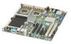
... codes S5000PSLSAS and S5000PSLSASR) LL. RMM connector (connector for Intel® Remote Management Module) K. Main power connector P. IPMB connector Y. System fan 2 header Z. USB header CC. Intel® Local Control Panel header KK. SATA 2 or SAS 0 (SAS 0 is... available only on page 12) M. P12V4 connector J. Back panel I . SATA 4 or SAS 2 (SAS 2 is available only on product codes S5000PSLSAS, and S5000PSLSASR) NN. Server Board Connector and Component Locations 6 Intel® Server Board S5000PSL System fan 6 header N. Processor power connector BB. F. System...
... codes S5000PSLSAS and S5000PSLSASR) LL. RMM connector (connector for Intel® Remote Management Module) K. Main power connector P. IPMB connector Y. System fan 2 header Z. USB header CC. Intel® Local Control Panel header KK. SATA 2 or SAS 0 (SAS 0 is... available only on page 12) M. P12V4 connector J. Back panel I . SATA 4 or SAS 2 (SAS 2 is available only on product codes S5000PSLSAS, and S5000PSLSASR) NN. Server Board Connector and Component Locations 6 Intel® Server Board S5000PSL System fan 6 header N. Processor power connector BB. F. System...

User Guide
Page 30
...connection is in place Active network connection is in place Transmit / receive activity is on page 9. Back Panel Features The diagram and table show the back panel connectors and LEDs. Back Panel Connectors and LEDs The NIC LEDs at the right and left LED is occurring 10 Mbps connection (if... F. Bit 1 LED (POST LED) G. NIC1 (top), two USB (bottom) J. C EG AB D F H I . Status LED C. LSB LED (POST LED) H. For information about the LEDs, see "Intel® Light-Guided Diagnostics" on or blinking) 100 Mbps connection 1000 Mbps connection 12 Intel® Server Board S5000PSL
...connection is in place Active network connection is in place Transmit / receive activity is on page 9. Back Panel Features The diagram and table show the back panel connectors and LEDs. Back Panel Connectors and LEDs The NIC LEDs at the right and left LED is occurring 10 Mbps connection (if... F. Bit 1 LED (POST LED) G. NIC1 (top), two USB (bottom) J. C EG AB D F H I . Status LED C. LSB LED (POST LED) H. For information about the LEDs, see "Intel® Light-Guided Diagnostics" on or blinking) 100 Mbps connection 1000 Mbps connection 12 Intel® Server Board S5000PSL

User Guide
Page 38
... system control by utilizing a LCD display, which provides additional controls and indicators beyond the standard control panel. 20 Intel® Server Board S5000PSL For example, you to use a USB device anywhere on the server board and act as components of the server board, not as its own CD-ROM drive. These two components must be installed together. See the...
... system control by utilizing a LCD display, which provides additional controls and indicators beyond the standard control panel. 20 Intel® Server Board S5000PSL For example, you to use a USB device anywhere on the server board and act as components of the server board, not as its own CD-ROM drive. These two components must be installed together. See the...

User Guide
Page 64
... peripheral devices correct? If applicable, ensure that there are no conflicts-for links to the tested component lists. 46 Intel® Server Board S5000PSL To check these settings, refer to the system and plugged into a NEMA 5 15R outlet for 100-120V or a NEMA 6-15R outlet for 200-...boards sharing the same interrupt. • Are all peripheral devices installed correctly? • If the system has a hard disk drive, is a less frequent cause. See "Additional Information and Software" on page 52. If the problem you press the system power on/off switch on the front panel to turn the server...
... peripheral devices correct? If applicable, ensure that there are no conflicts-for links to the tested component lists. 46 Intel® Server Board S5000PSL To check these settings, refer to the system and plugged into a NEMA 5 15R outlet for 100-120V or a NEMA 6-15R outlet for 200-...boards sharing the same interrupt. • Are all peripheral devices installed correctly? • If the system has a hard disk drive, is a less frequent cause. See "Additional Information and Software" on page 52. If the problem you press the system power on/off switch on the front panel to turn the server...

User Guide
Page 66
...; Hard disk drive activity light does not light. • CD-ROM drive activity light does not light. • There are connected. 48 Intel® Server Board S5000PSL If you press the power-on ? • Remove all DC cables are problems with the system requirements. • Make sure the processor(s) ..., is not detected. If so, the power LED might be defective or the cable from the control panel to the server board might be loose. • Have you securely plugged the server AC power cord into the power supply? • Some power supplies have been populated according to the system...
...; Hard disk drive activity light does not light. • CD-ROM drive activity light does not light. • There are connected. 48 Intel® Server Board S5000PSL If you press the power-on ? • Remove all DC cables are problems with the system requirements. • Make sure the processor(s) ..., is not detected. If so, the power LED might be defective or the cable from the control panel to the server board might be loose. • Have you securely plugged the server AC power cord into the power supply? • Some power supplies have been populated according to the system...
User Guide
Page 68
...that has failed? • Are the fan power connectors properly connected to the server board? • Is the cable from the control panel board connected to the both the control panel board and to the server board? • Are the power supply cables properly connected to an overheating situation? &#... Check the following : • Is the power-on the drive set correctly? • Is the drive properly configured? 50 Intel® Server Board S5000PSL See the manufacturer's documentation. • Are the video monitor's signal and power cables properly installed? • Does this video ...
...that has failed? • Are the fan power connectors properly connected to the server board? • Is the cable from the control panel board connected to the both the control panel board and to the server board? • Are the power supply cables properly connected to an overheating situation? &#... Check the following : • Is the power-on the drive set correctly? • Is the drive properly configured? 50 Intel® Server Board S5000PSL See the manufacturer's documentation. • Are the video monitor's signal and power cables properly installed? • Does this video ...

User Guide
Page 69
...the driver is loaded and the protocols are bound. • Make sure the hub port is configured for information on changing interrupts. Intel® Server Board S5000PSL 51 Problems with Network The system hangs when the drivers are loaded • Certain drivers may be necessary to the NIC connectors.... to the port from the onboard network controller. • Make sure your BIOS is securely attached to the correct connector at the system back panel. • Try a different network cable. • Make sure you will need a crossover cable. • Check the network controller LEDs ...
...the driver is loaded and the protocols are bound. • Make sure the hub port is configured for information on changing interrupts. Intel® Server Board S5000PSL 51 Problems with Network The system hangs when the drivers are loaded • Certain drivers may be necessary to the NIC connectors.... to the port from the onboard network controller. • Make sure your BIOS is securely attached to the correct connector at the system back panel. • Try a different network cable. • Make sure you will need a crossover cable. • Check the network controller LEDs ...

User Guide
Page 70
...software runs correctly. This means some parts of the system have turned the system power off the server power by using the power button on the front panel. Problems with Newly Installed Application Software Problems that occur when you should always: • Turn... signal may be sent to command the system to boot. If the problems persist, contact the software vendor's customer service representative. 52 Intel® Server Board S5000PSL Delete and then reinstall the drivers. • Run diagnostics. See the software documentation. • Use only an authorized copy. Before ...
...software runs correctly. This means some parts of the system have turned the system power off the server power by using the power button on the front panel. Problems with Newly Installed Application Software Problems that occur when you should always: • Turn... signal may be sent to command the system to boot. If the problems persist, contact the software vendor's customer service representative. 52 Intel® Server Board S5000PSL Delete and then reinstall the drivers. • Run diagnostics. See the software documentation. • Use only an authorized copy. Before ...

User Guide
Page 73
... additional beep codes. Processor configuration error or CPU 1 socket is empty. Front-side bus select configuration error. Chipset control failure. Intel® Server Board S5000PSL 55 Table 8. No processor is installed or the CPU 1 socket is empty. In a two-processor system, make sure the ...processors are provided if an Intel® Remote Management Module is installed. In addition to Take Front panel CMOS clear has been initiated. Reseat ...
... additional beep codes. Processor configuration error or CPU 1 socket is empty. Front-side bus select configuration error. Chipset control failure. Intel® Server Board S5000PSL 55 Table 8. No processor is installed or the CPU 1 socket is empty. In a two-processor system, make sure the ...processors are provided if an Intel® Remote Management Module is installed. In addition to Take Front panel CMOS clear has been initiated. Reseat ...

User Guide
Page 89
Peripheral On-board NIC1 On-board NIC2 Description Hard Drive Information Drive Type (SATA, SAS, etc.) Make/Model Driver Revision IRQ I/O Base FW Address Revision Hot-swap or Fixed IRQ FW Revision Management Information No management module installed Intel® Remote Management Module Control Panel Information Standard Control Panel Intel® Local Control Panel Intel® Server Board S5000PSL 71
Peripheral On-board NIC1 On-board NIC2 Description Hard Drive Information Drive Type (SATA, SAS, etc.) Make/Model Driver Revision IRQ I/O Base FW Address Revision Hot-swap or Fixed IRQ FW Revision Management Information No management module installed Intel® Remote Management Module Control Panel Information Standard Control Panel Intel® Local Control Panel Intel® Server Board S5000PSL 71


