
User Guide
Page 7
... memory, processor, control panel board, and battery, among other components you for purchasing and using the utilities shipped with the following Intel® Server Chassis: • Intel® Server Chassis SC5650UP (Intel® Server Board S3420GPLX and S3420GPLC) • Intel® Server Chassis SC5299DP/BRP (Intel® Server Board S3420GPLX and S3420GPLC) Intel®Server Board S3420GP User Guide vii This manual is available in the Technical Product Specification. See "Additional Information and Software" for troubleshooting, upgrading...
... memory, processor, control panel board, and battery, among other components you for purchasing and using the utilities shipped with the following Intel® Server Chassis: • Intel® Server Chassis SC5650UP (Intel® Server Board S3420GPLX and S3420GPLC) • Intel® Server Chassis SC5299DP/BRP (Intel® Server Board S3420GPLX and S3420GPLC) Intel®Server Board S3420GP User Guide vii This manual is available in the Technical Product Specification. See "Additional Information and Software" for troubleshooting, upgrading...

User Guide
Page 8
...: Processor, memory DIMMs, hard drive, floppy drive, CD-ROM or DVD-ROM drive, RAID controller, operating system. For information about this product, including BIOS settings and chipset information If you just received this product and need more of the screen and select the option to search "This Product." Additional Information and Software If you can be used with this product Processors that can go to install it Accessories or other Intel server...
...: Processor, memory DIMMs, hard drive, floppy drive, CD-ROM or DVD-ROM drive, RAID controller, operating system. For information about this product, including BIOS settings and chipset information If you just received this product and need more of the screen and select the option to search "This Product." Additional Information and Software If you can be used with this product Processors that can go to install it Accessories or other Intel server...

User Guide
Page 11
... Software viii Chapter 1: Server Board Features 17 Connector and Header Locations 21 Configuration Jumpers ...23 Back Panel Connectors ...24 RAID Support ...25 Hardware Requirements ...25 Processor ...26 Memory ...26 Power Supply ...27 Optional Hardware ...27 Intel® SAS Entry RAID Module AXX4SASMOD 27 Intel® Management Module 29 Intel® Local Control Panel 29 Chapter 2: Server Utilities 31 Using the BIOS Setup Utility 31 Starting Setup ...31 If You Cannot Access Setup 31 Setup Menus ...31 Upgrading the BIOS ...33 Preparing for the Upgrade 33 Upgrading...
... Software viii Chapter 1: Server Board Features 17 Connector and Header Locations 21 Configuration Jumpers ...23 Back Panel Connectors ...24 RAID Support ...25 Hardware Requirements ...25 Processor ...26 Memory ...26 Power Supply ...27 Optional Hardware ...27 Intel® SAS Entry RAID Module AXX4SASMOD 27 Intel® Management Module 29 Intel® Local Control Panel 29 Chapter 2: Server Utilities 31 Using the BIOS Setup Utility 31 Starting Setup ...31 If You Cannot Access Setup 31 Setup Menus ...31 Upgrading the BIOS ...33 Preparing for the Upgrade 33 Upgrading...
User Guide
Page 15
Configuration Jumpers Location 24 Figure 4. Back Panel Connectors 24 Figure 5. Remove the Processor Protective Cover 43 Figure 15. Removing the PCI Riser Assembly from the Server System 47 Figure 19. Diagnostic LED Placement Diagram 51 Intel® Server Board S3420GP User Guide xv Installing Memory 40 Figure 11. BMC Force Update Jumper 37 Figure 10. Lifting the Load Lever 42 Figure 12. Installing the Processor 44 Figure 16. Close the Load Plate and Socket Lever...
Configuration Jumpers Location 24 Figure 4. Back Panel Connectors 24 Figure 5. Remove the Processor Protective Cover 43 Figure 15. Removing the PCI Riser Assembly from the Server System 47 Figure 19. Diagnostic LED Placement Diagram 51 Intel® Server Board S3420GP User Guide xv Installing Memory 40 Figure 11. BMC Force Update Jumper 37 Figure 10. Lifting the Load Lever 42 Figure 12. Installing the Processor 44 Figure 16. Close the Load Plate and Socket Lever...

User Guide
Page 20
... • Intel® Server Board S3420GPLX and S3420GPLC: - Support for optional Intel® Remote Management Module 3 (Intel® Server board S3420GPLX) 18 Intel® Server Board S3420GP User Guide PCI Express* switch • Intel® Server Board S3420GPLC: - Internal connections: • Two USB 2x5 pin headers, each supporting two USB 2.0 ports (Only one header for Intel® Server board S3420GPV) • One 2x5 Serial Port B connector (Intel® Server board S3420GPLX and S3420GPLC) • Six SATA II connectors • One SAS mezzanine slot supports for Intel®...
... • Intel® Server Board S3420GPLX and S3420GPLC: - Support for optional Intel® Remote Management Module 3 (Intel® Server board S3420GPLX) 18 Intel® Server Board S3420GP User Guide PCI Express* switch • Intel® Server Board S3420GPLC: - Internal connections: • Two USB 2x5 pin headers, each supporting two USB 2.0 ports (Only one header for Intel® Server board S3420GPV) • One 2x5 Serial Port B connector (Intel® Server board S3420GPLX and S3420GPLC) • Six SATA II connectors • One SAS mezzanine slot supports for Intel®...

User Guide
Page 22
... RAID Technology II through onboard SATA connectors provides SATA RAID 0, 1, and 10. • Intel® Rapid Storage RAID through optional Intel® Integrated RAID Module SROMBSASMR (AXXROMBSASMR), provides RAID 0, 1, 5, 6 and striping capability for spans 10, 50, 60. One Gigabit Ethernet PHY 82578DM connected to PCI-E x1 interfaces on PCI-E x1 • Intel® Server Board S3420GPLX: - Remote Management Module III (RMM3) 20 Intel® Server Board S3420GP User Guide One Gigabit Ethernet device 82574L connect...
... RAID Technology II through onboard SATA connectors provides SATA RAID 0, 1, and 10. • Intel® Rapid Storage RAID through optional Intel® Integrated RAID Module SROMBSASMR (AXXROMBSASMR), provides RAID 0, 1, 5, 6 and striping capability for spans 10, 50, 60. One Gigabit Ethernet PHY 82578DM connected to PCI-E x1 interfaces on PCI-E x1 • Intel® Server Board S3420GPLX: - Remote Management Module III (RMM3) 20 Intel® Server Board S3420GP User Guide One Gigabit Ethernet device 82574L connect...

User Guide
Page 27
.... The BIOS Setup Utility provides drive configuration options on how to configure RAID, refer to four SATA ports [0/1/2/3] with IDE Legacy mode and two SATA ports [4/5] with IDE native Mode. • Compatibility: Supports up to six SATA ports with IDE Native Mode. • AHCI: Supports all SATA ports using the Advanced Host Controller Interface (AHCI). • SW RAID: Intel® Embedded Server RAID Technology II or Intel® Matrix Storage Technology is selected. RAID Support The Intel® Server Board S3420GP provides an embedded SATA controller that supports 3.0 Gbps...
.... The BIOS Setup Utility provides drive configuration options on how to configure RAID, refer to four SATA ports [0/1/2/3] with IDE Legacy mode and two SATA ports [4/5] with IDE native Mode. • Compatibility: Supports up to six SATA ports with IDE Native Mode. • AHCI: Supports all SATA ports using the Advanced Host Controller Interface (AHCI). • SW RAID: Intel® Embedded Server RAID Technology II or Intel® Matrix Storage Technology is selected. RAID Support The Intel® Server Board S3420GP provides an embedded SATA controller that supports 3.0 Gbps...

User Guide
Page 29
... a single-function PCI Express* end-point device. Power Supply A minimum of 5-V standby current or the board will not boot. Intel® Server Board S3420GP User Guide 27 All channels must provide a minimum of 3 A of 350 W is required. Optional Hardware Intel® SAS Entry RAID Module AXX4SASMOD The Intel® Server Board S3420GPLX provides a SAS module slot (J2H1) for Flash ROM and NVSRAM (Nonvolatile Static Random Access Memory) devices. The SAS controller supports the SAS protocol...
... a single-function PCI Express* end-point device. Power Supply A minimum of 5-V standby current or the board will not boot. Intel® Server Board S3420GP User Guide 27 All channels must provide a minimum of 3 A of 350 W is required. Optional Hardware Intel® SAS Entry RAID Module AXX4SASMOD The Intel® Server Board S3420GPLX provides a SAS module slot (J2H1) for Flash ROM and NVSRAM (Nonvolatile Static Random Access Memory) devices. The SAS controller supports the SAS protocol...
User Guide
Page 33
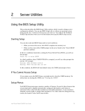
... Utilities Using the BIOS Setup Utility This section describes the BIOS Setup Utility options, which is used to the "Clear CMOS" position (enabled). You can enter and start BIOS Setup under several conditions: • When you turn on the server, after POST completes the memory test. • When you have adequate security rights to clear the CMOS memory. In the two conditions listed above, during the Power On Self Test (POST), you will find details about specific BIOS setup screens. Setup...
... Utilities Using the BIOS Setup Utility This section describes the BIOS Setup Utility options, which is used to the "Clear CMOS" position (enabled). You can enter and start BIOS Setup under several conditions: • When you turn on the server, after POST completes the memory test. • When you have adequate security rights to clear the CMOS memory. In the two conditions listed above, during the Power On Self Test (POST), you will find details about specific BIOS setup screens. Setup...
User Guide
Page 35
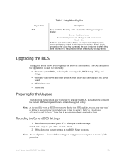
... BIOS update process, you want to obtain the upgrade utility. Intel® Server Board S3420GP User Guide 33 Boot the computer and press when you see the message: Press Key if you may need these settings to where they were before was pressed without affecting any existing values. Upgrading the BIOS The upgrade utility allows you to service. Write down the current settings in flash memory. Key to display: Setup Confirmation Save Configuration changes...
... BIOS update process, you want to obtain the upgrade utility. Intel® Server Board S3420GP User Guide 33 Boot the computer and press when you see the message: Press Key if you may need these settings to where they were before was pressed without affecting any existing values. Upgrading the BIOS The upgrade utility allows you to service. Write down the current settings in flash memory. Key to display: Setup Confirmation Save Configuration changes...
User Guide
Page 36
... regarding jumper settings, specific fixes, or other problem after reboot. Caution: Do not power down the system and reboot. A successful update ends with the BIOS image file. Refer to the update software. When the update completes, remove the bootable media from which you enter Setup, check your settings, save your hard drive. If this happens, shut down the system during the BIOS update process! Note: Before attempting a BIOS upgrade, review the instructions and...
... regarding jumper settings, specific fixes, or other problem after reboot. Caution: Do not power down the system and reboot. A successful update ends with the BIOS image file. Refer to the update software. When the update completes, remove the bootable media from which you enter Setup, check your settings, save your hard drive. If this happens, shut down the system during the BIOS update process! Note: Before attempting a BIOS upgrade, review the instructions and...

User Guide
Page 40
.... Power down and remove the AC power cord. 8. Move the jumper from the enabled position (covering pins 2 and 3) to load safely onto the flash device. Reconnect the AC cord and power up the server. 6. Close the server chassis. 5. Power down and remove the AC power cord. 2. Close the server chassis. 11. This jumper setting should complete the following procedure in update mode. 7. After successful completion of the firmware update process, the firmware update utility may...
.... Power down and remove the AC power cord. 8. Move the jumper from the enabled position (covering pins 2 and 3) to load safely onto the flash device. Reconnect the AC cord and power up the server. 6. Close the server chassis. 5. Power down and remove the AC power cord. 2. Close the server chassis. 11. This jumper setting should complete the following procedure in update mode. 7. After successful completion of the firmware update process, the firmware update utility may...

User Guide
Page 48
... the processor. 9. Raise the CPU load plate. 11. If installing a replacement processor, see "Installing the Processor". Remove the AC power cord from the processor. Otherwise, install the protective socket cover over the empty processor socket and reinstall the chassis cover. Installing a PCI Card This system does not include peripherals and add-in "Safety Information". 2. Refer to install a PCI card. Turn off all peripheral devices connected to a riser card when the riser card is removed from the chassis. 1. Twist the heatsink...
... the processor. 9. Raise the CPU load plate. 11. If installing a replacement processor, see "Installing the Processor". Remove the AC power cord from the processor. Otherwise, install the protective socket cover over the empty processor socket and reinstall the chassis cover. Installing a PCI Card This system does not include peripherals and add-in "Safety Information". 2. Refer to install a PCI card. Turn off all peripheral devices connected to a riser card when the riser card is removed from the chassis. 1. Twist the heatsink...
User Guide
Page 77
... Soft boot reset to all peripherals Press Reset button Power off and then on button Intel® Server Board S3420GP User Guide 75 This clears system memory, restarts POST, reloads the operating system, and halts power to clear the system memory and reload the operating system Clear system memory, restart POST, and reload the operating system Cold boot reset. See "Additional Information and Software" for assistance. Firmware upgrades include updates for components you are using one...
... Soft boot reset to all peripherals Press Reset button Power off and then on button Intel® Server Board S3420GP User Guide 75 This clears system memory, restarts POST, reloads the operating system, and halts power to clear the system memory and reload the operating system Clear system memory, restart POST, and reload the operating system Cold boot reset. See "Additional Information and Software" for assistance. Firmware upgrades include updates for components you are using one...

User Guide
Page 78
... a hard disk drive, is it properly formatted or configured? • Are all device drivers properly installed? • Are the configuration settings made in Setup correct? • Is the operating system properly loaded? Check the tested memory, and chassis lists, as well as the supported hardware and operating system list. To check these settings, refer to the tested component lists. 76 Intel® Server Board S3420GP User Guide Hardware failure is with a specific software application, see "Problems...
... a hard disk drive, is it properly formatted or configured? • Are all device drivers properly installed? • Are the configuration settings made in Setup correct? • Is the operating system properly loaded? Check the tested memory, and chassis lists, as well as the supported hardware and operating system list. To check these settings, refer to the tested component lists. 76 Intel® Server Board S3420GP User Guide Hardware failure is with a specific software application, see "Problems...
User Guide
Page 81
... video controller board, do not appear, the video display monitor or video controller may have failed. Intel® Server Board S3420GP User Guide 79 If you are still no characters on the screen after you reboot the system and POST emits a beep code, write down the beep code you hear. If you are using the onboard video controller. 2. If you do not receive a beep code and characters do the following: 1. Verify that the video controller board is useful...
... video controller board, do not appear, the video display monitor or video controller may have failed. Intel® Server Board S3420GP User Guide 79 If you are still no characters on the screen after you reboot the system and POST emits a beep code, write down the beep code you hear. If you are using the onboard video controller. 2. If you do not receive a beep code and characters do the following: 1. Verify that the video controller board is useful...
User Guide
Page 82
... the CD-ROM/DVD-ROM drive's power and signal cables properly installed? • Are all relevant switches and jumpers on the diskette drive set to "Disabled". If not, see "Power Light Does Not Light". • If your fans speeded up in response to a fan that "Onboard Floppy" is set correctly? • Is the diskette drive properly configured? • Is the diskette drive activity light always on? If you are using the onboard diskette controller, use the BIOS setup to make sure...
... the CD-ROM/DVD-ROM drive's power and signal cables properly installed? • Are all relevant switches and jumpers on the diskette drive set to "Disabled". If not, see "Power Light Does Not Light". • If your fans speeded up in response to a fan that "Onboard Floppy" is set correctly? • Is the diskette drive properly configured? • Is the diskette drive activity light always on? If you are using the onboard diskette controller, use the BIOS setup to make sure...

User Guide
Page 83
... adapter supports shared interrupts. Make sure your PCI card(s) for a link to the current version. • Make sure the other PCI drivers. Refer to the "Additional Information and Software" for information on -board network controller. • Make sure your BIOS is current. Intel® Server Board S3420GP User Guide 81 See "Additional Information and Software" for the same duplex mode as the network controller. • Make sure the correct networking software...
... adapter supports shared interrupts. Make sure your PCI card(s) for a link to the current version. • Make sure the other PCI drivers. Refer to the "Additional Information and Software" for information on -board network controller. • Make sure your BIOS is current. Intel® Server Board S3420GP User Guide 81 See "Additional Information and Software" for the same duplex mode as the network controller. • Make sure the correct networking software...

User Guide
Page 84
... the problems persist, contact the software vendor's customer service representative. 82 Intel® Server Board S3420GP User Guide Before installing a PCI card, you have turned the system power off the server power by using the power button on the front panel. Faulty equipment is unlikely, especially if other adapter supports shared interrupts. Make sure your operating system supports shared interrupts. • Try reseating the add-in adapter stopped working without...
... the problems persist, contact the software vendor's customer service representative. 82 Intel® Server Board S3420GP User Guide Before installing a PCI card, you have turned the system power off the server power by using the power button on the front panel. Faulty equipment is unlikely, especially if other adapter supports shared interrupts. Make sure your operating system supports shared interrupts. • Try reseating the add-in adapter stopped working without...
User Guide
Page 86
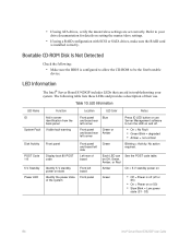
... BIOS is configured to allow the CD-ROM to turn the LED on setting the master/slave settings. • If using ATA drives, verify the master/slave settings are set correctly. Left rear of board Each LED can aid in server identification from the back panel Visible fault warning Front panel Display boot 80 POST code Identify 5-V standby power on or S0) • Slow Blink = Low power state (S1 - LED Information The Intel...
... BIOS is configured to allow the CD-ROM to turn the LED on setting the master/slave settings. • If using ATA drives, verify the master/slave settings are set correctly. Left rear of board Each LED can aid in server identification from the back panel Visible fault warning Front panel Display boot 80 POST code Identify 5-V standby power on or S0) • Slow Blink = Low power state (S1 - LED Information The Intel...


