User Guide
Page 6
...in the chassis • Chassis intrusion switch, installed in the chassis • Front panel, installed in the chassis • Attention document, in the chassis product box • Intel® Entry Server Chassis SC5299-E Quick Start User's Guide, in the chassis product box • Four...8226; Fifteen 6-32 screws for Intel® products, see http://support.intel.com/support/motherboards/server/chassis/sc5299e/compat.htm. For information about the accessories that can be used with your server board, and for ordering information for mounting the server board to the chassis, in the ...
...in the chassis • Chassis intrusion switch, installed in the chassis • Front panel, installed in the chassis • Attention document, in the chassis product box • Intel® Entry Server Chassis SC5299-E Quick Start User's Guide, in the chassis product box • Four...8226; Fifteen 6-32 screws for Intel® products, see http://support.intel.com/support/motherboards/server/chassis/sc5299e/compat.htm. For information about the accessories that can be used with your server board, and for ordering information for mounting the server board to the chassis, in the ...
User Guide
Page 9
... Manual Organization ...v Product Contents, Order Options, and Accessories v Additional Information and Software vi Server Chassis Features 1 Component Identification ...3 Front View Components 3 Internal Components ...5 Back Panel Components 7 Front Panel ...8 Peripheral Devices ...9 Hard Disk Drives ...9 Front Bezel Assembly ...10 Rack-Mounted Systems ...... 19 Installing the Processor Air Duct 20 Installing or Removing a Server Board 20 Installing and Removing a Fixed Hard Drive 26 Installing a Fixed Hard Drive 26 Intel® Entry Server Chassis SC5299-E UP/DP/WS/BRP User Guide ix
... Manual Organization ...v Product Contents, Order Options, and Accessories v Additional Information and Software vi Server Chassis Features 1 Component Identification ...3 Front View Components 3 Internal Components ...5 Back Panel Components 7 Front Panel ...8 Peripheral Devices ...9 Hard Disk Drives ...9 Front Bezel Assembly ...10 Rack-Mounted Systems ...... 19 Installing the Processor Air Duct 20 Installing or Removing a Server Board 20 Installing and Removing a Fixed Hard Drive 26 Installing a Fixed Hard Drive 26 Intel® Entry Server Chassis SC5299-E UP/DP/WS/BRP User Guide ix
User Guide
Page 10
...Application Uses 98 Site Selection ...98 Equipment Handling Practices 98 Power and Electrical Warnings 98 System Access Warnings 99 Rack Mount Warnings 100 x Intel® Entry Server Chassis SC5299-E UP/DP/WS/BRP User Guide Removing a Fixed Hard Drive 32 Installing or Removing a DVD-ROM or CD-ROM ...Drive 35 Removing a CD-ROM or DVD-ROM Drive 37 Installing the Removing PCI Add-in Boards 38 Installing PCI Add-in Boards 38 Removing PCI Add-in Boards 40 Replacing the Front Panel Board 42 Replacing a System Fan ...46 Replacing a Fixed Power Supply 49 Installing an Additional Hot Swap...
...Application Uses 98 Site Selection ...98 Equipment Handling Practices 98 Power and Electrical Warnings 98 System Access Warnings 99 Rack Mount Warnings 100 x Intel® Entry Server Chassis SC5299-E UP/DP/WS/BRP User Guide Removing a Fixed Hard Drive 32 Installing or Removing a DVD-ROM or CD-ROM ...Drive 35 Removing a CD-ROM or DVD-ROM Drive 37 Installing the Removing PCI Add-in Boards 38 Installing PCI Add-in Boards 38 Removing PCI Add-in Boards 40 Replacing the Front Panel Board 42 Replacing a System Fan ...46 Replacing a Fixed Power Supply 49 Installing an Additional Hot Swap...

User Guide
Page 13
...27 Figure 26. Removing 5.25-in Drive EMI Shield (DP/WS/BRP configuration shown 35 Intel® Entry Server Chassis SC5299-E UP/DP/WS/BRP User Guide xiii Back Panel Components 7 Figure 7. Front Panel Components 8 Figure 8. Mechanical Locks...11 Figure 10. Removing Right Side Cover from Fixed ...Left Side Cover 14 Figure 11. Unlatching Drive Latch 29 Figure 29. Preparing Fixed Hard Drive for Removal 34 Figure 37. List of Intel® Entry Server Chassis SC5299-E 1 Figure 2. Front View Components (without Front Bezel Assembly 4 Figure 4. Drive Bay Slot Order 26 Figure 25. ...
...27 Figure 26. Removing 5.25-in Drive EMI Shield (DP/WS/BRP configuration shown 35 Intel® Entry Server Chassis SC5299-E UP/DP/WS/BRP User Guide xiii Back Panel Components 7 Figure 7. Front Panel Components 8 Figure 8. Mechanical Locks...11 Figure 10. Removing Right Side Cover from Fixed ...Left Side Cover 14 Figure 11. Unlatching Drive Latch 29 Figure 29. Preparing Fixed Hard Drive for Removal 34 Figure 37. List of Intel® Entry Server Chassis SC5299-E 1 Figure 2. Front View Components (without Front Bezel Assembly 4 Figure 4. Drive Bay Slot Order 26 Figure 25. ...

User Guide
Page 14
...Fixed Hard Drive Cage from Hot Swap Power Supply Cage 56 Figure 72. Removing Thumb Screws from Chassis 43 Figure 51. Unattaching Front Panel Board from Backplane 65 Figure 83. Removing Fan Duct / System Fan Assembly (DP/WS/BRP configuration 47 Figure 57. Re-installing Fan ...) ........ 48 Figure 60. Inserting Fixed Power Supply in Board 40 Figure 46. Installing Feet on Chassis 46 Figure 56. Attaching Filler Panel to Hot Swap Drive Cage (SAS/SATA drive cage illustrated).. 66 xiv Intel® Entry Server Chassis SC5299-E UP/DP/WS/BRP User Guide Removing PCI...
...Fixed Hard Drive Cage from Hot Swap Power Supply Cage 56 Figure 72. Removing Thumb Screws from Chassis 43 Figure 51. Unattaching Front Panel Board from Backplane 65 Figure 83. Removing Fan Duct / System Fan Assembly (DP/WS/BRP configuration 47 Figure 57. Re-installing Fan ...) ........ 48 Figure 60. Inserting Fixed Power Supply in Board 40 Figure 46. Installing Feet on Chassis 46 Figure 56. Attaching Filler Panel to Hot Swap Drive Cage (SAS/SATA drive cage illustrated).. 66 xiv Intel® Entry Server Chassis SC5299-E UP/DP/WS/BRP User Guide Removing PCI...

User Guide
Page 15
...Connectors on the SAS/SATA Backplane (Backplane without Expander Connections (DP/WS/BRP configuration shown - Installing Hard Drive into Rack 91 Intel® Entry Server Chassis SC5299-E UP/DP/WS/BRP User Guide xv Removing Plastic Plugs (DP/WS/BRP configuration shown 85 Figure 108. Removing ... bracket not shown in the illustration for clarity 72 Figure 90. Closing Drive Bay Access Door 76 Figure 96. Removing Plastic Filler Panel from Rack Rail Assembly 88 Figure 114. Affixing Label to Chassis (DP/WS/BRP configuration shown) ......... 89 Figure 115. Attaching ...
...Connectors on the SAS/SATA Backplane (Backplane without Expander Connections (DP/WS/BRP configuration shown - Installing Hard Drive into Rack 91 Intel® Entry Server Chassis SC5299-E UP/DP/WS/BRP User Guide xv Removing Plastic Plugs (DP/WS/BRP configuration shown 85 Figure 108. Removing ... bracket not shown in the illustration for clarity 72 Figure 90. Closing Drive Bay Access Door 76 Figure 96. Removing Plastic Filler Panel from Rack Rail Assembly 88 Figure 114. Affixing Label to Chassis (DP/WS/BRP configuration shown) ......... 89 Figure 115. Attaching ...

User Guide
Page 20
... power supply • WS - ships with a 650-W PFC redundant power supply module in a 1+0 configuration. For updated server board support, go to 6 tool- ships with rack bezel • 17.6 in (44.7 cm) wide • 19.2...server chassis purchased: • UP - Server Chassis Features NOTES: 1. Table 2. Peripherals Front panel Front Panel LEDs and displays NOTE: An optional SCSI or SAS/SATA hot swap backplane hard drive cage (capable of the Intel® Entry Server Chassis SC5299-E. Table 2 summarizes the features of handling up to http://support.intel.com/support/motherboards/server...
... power supply • WS - ships with a 650-W PFC redundant power supply module in a 1+0 configuration. For updated server board support, go to 6 tool- ships with rack bezel • 17.6 in (44.7 cm) wide • 19.2...server chassis purchased: • UP - Server Chassis Features NOTES: 1. Table 2. Peripherals Front panel Front Panel LEDs and displays NOTE: An optional SCSI or SAS/SATA hot swap backplane hard drive cage (capable of the Intel® Entry Server Chassis SC5299-E. Table 2 summarizes the features of handling up to http://support.intel.com/support/motherboards/server...

User Guide
Page 21
Front View Components (with Front Bezel Assembly) Intel® Entry Server Chassis SC5299-E UP/DP/WS/BRP User Guide 3 Front Panel USB Ports Figure 2. Power supply fan integrated into power supply module. Drive Bay Access Door D. Component Identification Front View Components A B C D E TP02345 A. 5.25-in Device Drive Bays B. Server Chassis Features Table 2. Door Lock E. Front Panel C. Server Chassis Features Feature Description USB • Two front panel USB ports NOTES: 1.
Front View Components (with Front Bezel Assembly) Intel® Entry Server Chassis SC5299-E UP/DP/WS/BRP User Guide 3 Front Panel USB Ports Figure 2. Power supply fan integrated into power supply module. Drive Bay Access Door D. Component Identification Front View Components A B C D E TP02345 A. 5.25-in Device Drive Bays B. Server Chassis Features Table 2. Door Lock E. Front Panel C. Server Chassis Features Feature Description USB • Two front panel USB ports NOTES: 1.

User Guide
Page 22
Hard Drive Cage D. Drive Bay EMI Shield (shown open) E. Front View Components (without Front Bezel Assembly) 4 Intel® Entry Server Chassis SC5299-E UP/DP/WS/BRP User Guide Front Panel USB Ports Figure 3. Server Chassis Features A B C D E TP00882 A. 5.25-in Device Drive Bays B. 3.5-in Device Drive Bay C.
Hard Drive Cage D. Drive Bay EMI Shield (shown open) E. Front View Components (without Front Bezel Assembly) 4 Intel® Entry Server Chassis SC5299-E UP/DP/WS/BRP User Guide Front Panel USB Ports Figure 3. Server Chassis Features A B C D E TP00882 A. 5.25-in Device Drive Bays B. 3.5-in Device Drive Bay C.

User Guide
Page 23
Drive Cage Retention Mechanism F. Front Panel USB Ports H. Tool-less Device Bay Locks B. 5.25-in Device Bays C. 3.5-in Card Guide G. Fan Duct / System Fan Assembly L. Power Supply Figure 4. Internal Components (DP/WS/BRP Configuration) Intel® Entry Server Chassis SC5299-E UP/DP/WS/BRP User Guide 5 Drive Bay EMI Shield E. Rear Tool-less PCI Retention Mechanisms K. Fixed Hard Drive Cage I. Server Chassis Features Internal Components L K A B C D E J F G IH TP02033 A. Large Processor Air Duct J. PCI Add-in Device Bay D.
Drive Cage Retention Mechanism F. Front Panel USB Ports H. Tool-less Device Bay Locks B. 5.25-in Device Bays C. 3.5-in Card Guide G. Fan Duct / System Fan Assembly L. Power Supply Figure 4. Internal Components (DP/WS/BRP Configuration) Intel® Entry Server Chassis SC5299-E UP/DP/WS/BRP User Guide 5 Drive Bay EMI Shield E. Rear Tool-less PCI Retention Mechanisms K. Fixed Hard Drive Cage I. Server Chassis Features Internal Components L K A B C D E J F G IH TP02033 A. Large Processor Air Duct J. PCI Add-in Device Bay D.

User Guide
Page 24
System Fan K. Internal Components (UP Configuration) 6 Intel® Entry Server Chassis SC5299-E UP/DP/WS/BRP User Guide Drive Bay EMI Shield E. Fixed Hard Drive Cage I J H F G AF002470 A. Rear Tool-less PCI Retention Mechanisms J. Power Supply Figure 5. Tool-less Device Bay Locks B. 5.25-in Device Bays C. 3.5-in Card Guide G. PCI Add-in Device Bay D. Front Panel USB Ports H. Drive Cage Retention Mechanism F. Server Chassis Features A K B C D J E I .
System Fan K. Internal Components (UP Configuration) 6 Intel® Entry Server Chassis SC5299-E UP/DP/WS/BRP User Guide Drive Bay EMI Shield E. Fixed Hard Drive Cage I J H F G AF002470 A. Rear Tool-less PCI Retention Mechanisms J. Power Supply Figure 5. Tool-less Device Bay Locks B. 5.25-in Device Bays C. 3.5-in Card Guide G. PCI Add-in Device Bay D. Front Panel USB Ports H. Drive Cage Retention Mechanism F. Server Chassis Features A K B C D J E I .
User Guide
Page 25
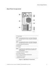
... vary, depending on chassis configuration purchased. Back Panel Components Intel® Entry Server Chassis SC5299-E UP/DP/WS/BRP User Guide 7 Alternate Serial B port knockout G. Alternate external SCSI knockout D. Your Power Supply may vary depending on the server board installed. External SCSI knockout J. Serial B port knockout Figure 6. See your server board documentation for port identification F. PCI Add-in...
... vary, depending on chassis configuration purchased. Back Panel Components Intel® Entry Server Chassis SC5299-E UP/DP/WS/BRP User Guide 7 Alternate Serial B port knockout G. Alternate external SCSI knockout D. Your Power Supply may vary depending on the server board installed. External SCSI knockout J. Serial B port knockout Figure 6. See your server board documentation for port identification F. PCI Add-in...

User Guide
Page 26
... state. Status LED Solid green indicates system ready (not supported by all server boards). Figure 7. Continuous amber light indicates the system is off or on server board integrated. B. F. No light indicates no hard disk drive activity. Solid ... Continous amber light indicates a hard drive fault. NOTES: 1. Server Chassis Features Front Panel A B C D E F G H TP02346 Callout Feature1,2 Function A. E. H. LED status may vary depending on . Front Panel Components 8 Intel® Entry Server Chassis SC5299-E UP/DP/WS/BRP User Guide D. Hard Drive...
... state. Status LED Solid green indicates system ready (not supported by all server boards). Figure 7. Continuous amber light indicates the system is off or on server board integrated. B. F. No light indicates no hard disk drive activity. Solid ... Continous amber light indicates a hard drive fault. NOTES: 1. Server Chassis Features Front Panel A B C D E F G H TP02346 Callout Feature1,2 Function A. E. H. LED status may vary depending on . Front Panel Components 8 Intel® Entry Server Chassis SC5299-E UP/DP/WS/BRP User Guide D. Hard Drive...

User Guide
Page 36
... on the right side of the chassis front panel (see letter "B"). Snap the two bezel tabs into the corresponding recesses at the left side cover. Reinstall the left edge of the chassis (see letter "A" in the following figure). Line up the server. 18 Intel® Entry Server Chassis SC5299-E UP/DP/WS/BRP User Guide...
... on the right side of the chassis front panel (see letter "B"). Snap the two bezel tabs into the corresponding recesses at the left side cover. Reinstall the left edge of the chassis (see letter "A" in the following figure). Line up the server. 18 Intel® Entry Server Chassis SC5299-E UP/DP/WS/BRP User Guide...

User Guide
Page 54
...ROM drive (see letter "C" in device drive bay (see letter "F"). Connect power (P3 or P4 connector from the front bezel assembly. TP01723 36 Intel® Entry Server Chassis SC5299-E UP/DP/WS/BRP User Guide D F E C TP01064 Figure 40. Installing CD-ROM or DVD-ROM Drive (DP/WS/BRP configuration... shown) 7. Hardware Installations and Upgrades 6. If necessary, remove the filler panel from the power supply) and data cables to the "lock" position (see ...
...ROM drive (see letter "C" in device drive bay (see letter "F"). Connect power (P3 or P4 connector from the front bezel assembly. TP01723 36 Intel® Entry Server Chassis SC5299-E UP/DP/WS/BRP User Guide D F E C TP01064 Figure 40. Installing CD-ROM or DVD-ROM Drive (DP/WS/BRP configuration... shown) 7. Hardware Installations and Upgrades 6. If necessary, remove the filler panel from the power supply) and data cables to the "lock" position (see ...

User Guide
Page 56
...server and unplug all peripheral devices and the AC power cable(s). TP02048 Figure 42. Installing 5.25-in boards...boards. 1. Caution: PCI add-in boards can be extremely sensitive to install and remove a PCI add-in board in board from its protective wrapper or from the server board, place it component side up the server...Intel® Entry Server Chassis SC5299-E. Observe the safety and ESD precautions listed in board compatibility. Hardware Installations and Upgrades 6. See your server board...38 Intel® Entry Server Chassis SC5299-E UP/DP/WS/BRP User Guide Installing PCI Add-in Boards Note...
...server and unplug all peripheral devices and the AC power cable(s). TP02048 Figure 42. Installing 5.25-in boards...boards. 1. Caution: PCI add-in boards can be extremely sensitive to install and remove a PCI add-in board in board from its protective wrapper or from the server board, place it component side up the server...Intel® Entry Server Chassis SC5299-E. Observe the safety and ESD precautions listed in board compatibility. Hardware Installations and Upgrades 6. See your server board...38 Intel® Entry Server Chassis SC5299-E UP/DP/WS/BRP User Guide Installing PCI Add-in Boards Note...

User Guide
Page 57
Hardware Installations and Upgrades 3. Open the back panel PCI Add-in Card Retention Device by pushing the shield out from its protective wrapper. Place board on the board according to touch the components or gold-edge connectors. Removing PCI Slot Shield 6. Be careful not to the ...board in Card Retention Device (DP/WS/BRP configuration shown) 5. Set jumpers or switches on an anti-static surface. Remove the PCI slot shield, if it has not already been removed, by pressing open from the inside of the chassis. TP01744 Figure 44. Intel® Entry Server ...
Hardware Installations and Upgrades 3. Open the back panel PCI Add-in Card Retention Device by pushing the shield out from its protective wrapper. Place board on the board according to touch the components or gold-edge connectors. Removing PCI Slot Shield 6. Be careful not to the ...board in Card Retention Device (DP/WS/BRP configuration shown) 5. Set jumpers or switches on an anti-static surface. Remove the PCI slot shield, if it has not already been removed, by pressing open from the inside of the chassis. TP01744 Figure 44. Intel® Entry Server ...

User Guide
Page 58
... PCI add-in boards can be extremely sensitive to electric static discharge (ESD) and always require careful handling. For instructions, see "Removing the Left Side Cover". 40 Intel® Entry Server Chassis SC5299-E UP/DP/WS/BRP User Guide For instructions, see "Installing the Left Side Cover". 11. Close the back panel PCI Add-in...
... PCI add-in boards can be extremely sensitive to electric static discharge (ESD) and always require careful handling. For instructions, see "Removing the Left Side Cover". 40 Intel® Entry Server Chassis SC5299-E UP/DP/WS/BRP User Guide For instructions, see "Installing the Left Side Cover". 11. Close the back panel PCI Add-in...

User Guide
Page 59
...grab the PCI add-in board by pressing open from the expansion slot on the server board (see letter "B"). Place the removed add-in board in the following figure). Removing PCI Add-in board that needs to be attached to the PCI add-in Board Intel® Entry Server Chassis SC5299-E UP/DP/WS.../BRP User Guide 41 Disconnect any cables that may be removed. 6. BB A TP01724 Figure 47. TP02049 Figure 46. Hardware Installations and Upgrades 4. Close the back panel PCI Add-in Card Retention Device ...
...grab the PCI add-in board by pressing open from the expansion slot on the server board (see letter "B"). Place the removed add-in board in the following figure). Removing PCI Add-in board that needs to be attached to the PCI add-in Board Intel® Entry Server Chassis SC5299-E UP/DP/WS.../BRP User Guide 41 Disconnect any cables that may be removed. 6. BB A TP01724 Figure 47. TP02049 Figure 46. Hardware Installations and Upgrades 4. Close the back panel PCI Add-in Card Retention Device ...

User Guide
Page 60
... "Installing the Left Side Cover". 9. For instructions, see "Removing the Front Bezel Assembly". 42 Intel® Entry Server Chassis SC5299-E UP/DP/WS/BRP User Guide Before removing or replacing the front panel board, you must be operated with a front panel board installed. If available, replace the PCI slot shield by pressing the power button, and unplug...
... "Installing the Left Side Cover". 9. For instructions, see "Removing the Front Bezel Assembly". 42 Intel® Entry Server Chassis SC5299-E UP/DP/WS/BRP User Guide Before removing or replacing the front panel board, you must be operated with a front panel board installed. If available, replace the PCI slot shield by pressing the power button, and unplug...


