
Product Specification
Page 4
... Intel® Server Board S3000PT TPS 4.4 Loading BIOS Defaults 49 5. Connectors and Jumper Blocks 64 7.1 Power Connectors 64 7.2 SMBus Header ...64 7.3 Front Panel Connector 65 7.4 I/O Connectors ...65 7.4.1 VGA Connector ...65 7.4.2 NIC Connectors...66 7.4.3 SATA Connectors 66 iv Revision 1.3 Platform Management Architecture 50 5.1 Console Redirection 50 5.1.1 Serial Configuration Settings 50 5.1.2 Keystroke Mappings 50 5.1.3 5.2 Limitations ...51 Intel® Active Management Technology (AMT 51 5.3 Wired For Management (WFM 53 5.3.1 PXE BIOS Support...
... Intel® Server Board S3000PT TPS 4.4 Loading BIOS Defaults 49 5. Connectors and Jumper Blocks 64 7.1 Power Connectors 64 7.2 SMBus Header ...64 7.3 Front Panel Connector 65 7.4 I/O Connectors ...65 7.4.1 VGA Connector ...65 7.4.2 NIC Connectors...66 7.4.3 SATA Connectors 66 iv Revision 1.3 Platform Management Architecture 50 5.1 Console Redirection 50 5.1.1 Serial Configuration Settings 50 5.1.2 Keystroke Mappings 50 5.1.3 5.2 Limitations ...51 Intel® Active Management Technology (AMT 51 5.3 Wired For Management (WFM 53 5.3.1 PXE BIOS Support...

Product Specification
Page 6
...Setup Utility - Setup Utility - SATA Controller Configuration Screen Display 33 Figure 11. Setup Utility - Serial Port Configuration Screen Display 35 Figure 12. Boot Configuration Screen Display 38 Figure 16. Security Configuration Screen Display 41 Figure 19. Console Redirection Screen Display 44 Figure 21. Boot Options Display 46 Figure 23. Error Manager Screen Displa y 47 Figure 25. Exit Screen Display 48 Figure 26. Fan Speed Control Block Diagram 79 vi Revision 1.3 Intel® Server Board S3000PT Block Diagram 6 Figure 3. Setup Utility - Setup Utility - Memory...
...Setup Utility - Setup Utility - SATA Controller Configuration Screen Display 33 Figure 11. Setup Utility - Serial Port Configuration Screen Display 35 Figure 12. Boot Configuration Screen Display 38 Figure 16. Security Configuration Screen Display 41 Figure 19. Console Redirection Screen Display 44 Figure 21. Boot Options Display 46 Figure 23. Error Manager Screen Displa y 47 Figure 25. Exit Screen Display 48 Figure 26. Fan Speed Control Block Diagram 79 vi Revision 1.3 Intel® Server Board S3000PT Block Diagram 6 Figure 3. Setup Utility - Setup Utility - Memory...

Product Specification
Page 8
... Table 65. Monitored Components 78 viii Revision 1.3 POST Error Beep Codes 63 Table 45. NIC2- Optional USB Connection Header Pin -out (J1C1 68 Table 56. 8-pin Fan Headers Pin-out (J3K1,J4K2,J4K1 68 Table 57. Error Manager Screen Fields 47 Table 33. SMBus Header Pin-out (J1A1 64 Table 47. External DB9 Serial A Port Pin -out (J3A1 67 Table 53. List of Tables Intel® Server Board S3000PT TPS Table 32. Setup Utility - Setup Utility - Exit Screen Fields 48 Table...
... Table 65. Monitored Components 78 viii Revision 1.3 POST Error Beep Codes 63 Table 45. NIC2- Optional USB Connection Header Pin -out (J1C1 68 Table 56. 8-pin Fan Headers Pin-out (J3K1,J4K2,J4K1 68 Table 57. Error Manager Screen Fields 47 Table 33. SMBus Header Pin-out (J1A1 64 Table 47. External DB9 Serial A Port Pin -out (J3A1 67 Table 53. List of Tables Intel® Server Board S3000PT TPS Table 32. Setup Utility - Setup Utility - Exit Screen Fields 48 Table...
Product Specification
Page 11
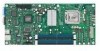
... 14-pin SSI front panel 2x9 power connectors Fan support - Three customized 8-pin fan headers with an additional internal header providing two optional USB ports for front panel support. - One 4-pin fan header without PWM and Tach capability Intel® Light-guided Diagnostic LEDs to display POST code indicato rs during boot Revision 1.3 3 Intel® Server Board S3000PT TPS Server Board Overview Two external USB ports with PWM and Tach capability - Supports legacy keyboard/m ouse connections when using PS /2-USB dongle LPC (Low Pin Count) bus...
... 14-pin SSI front panel 2x9 power connectors Fan support - Three customized 8-pin fan headers with an additional internal header providing two optional USB ports for front panel support. - One 4-pin fan header without PWM and Tach capability Intel® Light-guided Diagnostic LEDs to display POST code indicato rs during boot Revision 1.3 3 Intel® Server Board S3000PT TPS Server Board Overview Two external USB ports with PWM and Tach capability - Supports legacy keyboard/m ouse connections when using PS /2-USB dongle LPC (Low Pin Count) bus...

Product Specification
Page 15
... -32 instruction set, while supporting 64 -bit native mode operation when coupled with dual core, Hyper -Threading Technology or Intel® EM64T. 3.1.1 Processor Voltage Regulator Down (VRD) The Intel® Server Board S3000PT has a VRD (Voltage Regulator Down) to as the Intel® LGA775 socket). The processors in the 775-land package, like their predecessors in the 775 -land package, utilize Flip-Chip Land Grid Array (FC-LGA4) package technology and plug into...
... -32 instruction set, while supporting 64 -bit native mode operation when coupled with dual core, Hyper -Threading Technology or Intel® EM64T. 3.1.1 Processor Voltage Regulator Down (VRD) The Intel® Server Board S3000PT has a VRD (Voltage Regulator Down) to as the Intel® LGA775 socket). The processors in the 775-land package, like their predecessors in the 775 -land package, utilize Flip-Chip Land Grid Array (FC-LGA4) package technology and plug into...

Product Specification
Page 19
...-bit/33-MHz PCI bus. Once configured, each appears to support low -speed Legacy I /O Controller Hub 7R The Intel® ICH7R controller has several components. Intel® Server Board S3000PT TPS Functional Architecture 3.2.2 I/O Controller Hub 3.2.2.1 Intel® ICH7R: I /O. The board uses the following : A DMI bus A PCI 32-bit/33-MHz interface An IDE interface An integrated serial ATA Host controller A USB controller A PCI Express* x4 interface Two PCI Express* x1 interface A power management controller...
...-bit/33-MHz PCI bus. Once configured, each appears to support low -speed Legacy I /O Controller Hub 7R The Intel® ICH7R controller has several components. Intel® Server Board S3000PT TPS Functional Architecture 3.2.2 I/O Controller Hub 3.2.2.1 Intel® ICH7R: I /O. The board uses the following : A DMI bus A PCI 32-bit/33-MHz interface An IDE interface An integrated serial ATA Host controller A USB controller A PCI Express* x4 interface Two PCI Express* x1 interface A power management controller...
Product Specification
Page 29
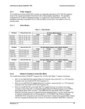
... 11. Intel® Server Board S3000PT TPS Functional Architecture 3.5.1 Video Support The Intel® Server Board S300 0PT includes an integrated standalone ATI* ES1000 graphics engine that is an Intel® 82573V Gigabit Ethernet Controller resourced with a x1 PCI Express* interface from the Intel® ICH7R (PCI Segment C). NIC2 is footprint compatible with analog display capabilities. The baseboard provides a standard 15 -pin VGA connector at the rear of dedicated memory to...
... 11. Intel® Server Board S3000PT TPS Functional Architecture 3.5.1 Video Support The Intel® Server Board S300 0PT includes an integrated standalone ATI* ES1000 graphics engine that is an Intel® 82573V Gigabit Ethernet Controller resourced with a x1 PCI Express* interface from the Intel® ICH7R (PCI Segment C). NIC2 is footprint compatible with analog display capabilities. The baseboard provides a standard 15 -pin VGA connector at the rear of dedicated memory to...
Product Specification
Page 31
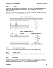
... I /O panel of BIOS and non-volatile storage space. Serial A Header Pin-out Signal Name Serial Port A Header Pin -out Table 15. Serial B is connected through th e SPI bus from the Intel® ICH7R controller. Intel® Server Board S3000PT TPS Functional Architecture 3.5.3.1.1 Serial Port A Serial A is a standard DB9 interface located at the rear I /O contains functionality that allows various events to control the power -on and power-off the system. 3.5.4 BIOS Flash The board incorporates a SPI flash memory which can be used to support keyboard...
... I /O panel of BIOS and non-volatile storage space. Serial A Header Pin-out Signal Name Serial Port A Header Pin -out Table 15. Serial B is connected through th e SPI bus from the Intel® ICH7R controller. Intel® Server Board S3000PT TPS Functional Architecture 3.5.3.1.1 Serial Port A Serial A is a standard DB9 interface located at the rear I /O contains functionality that allows various events to control the power -on and power-off the system. 3.5.4 BIOS Flash The board incorporates a SPI flash memory which can be used to support keyboard...
Product Specification
Page 38
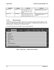
... Help text depends on the Advanced screen. To access this screen, the user selects the option that is to 23. Main Advanced Security ► Processor ► Memory ► IDE Controller ► Serial Port ► USB Controller ► PCI ► Power ► Boot Configuration ► Hardware Health configuration Server Management Boot Options Boot Manager Error Manager Exit Figure 7. Seconds valid values are 0 to 59. Configurations are performed on the selected screen, not directly on the sub...
... Help text depends on the Advanced screen. To access this screen, the user selects the option that is to 23. Main Advanced Security ► Processor ► Memory ► IDE Controller ► Serial Port ► USB Controller ► PCI ► Power ► Boot Configuration ► Hardware Health configuration Server Management Boot Options Boot Manager Error Manager Exit Figure 7. Seconds valid values are 0 to 59. Configurations are performed on the selected screen, not directly on the sub...

Product Specification
Page 40
... Disable Bit featu re (XD bit). System BIOS Intel® Server Board S3000PT TPS Setup Item HyperThreading Technology Options Enable Disable Enhanced SpeedStep Enable Disable Virtualization Technology Enable Disable Execute Disable Bit Enable Disable Help Text Enables or disables Intel® HyperThreading Technology on the processors. Memory Configuration Screen Display 32 Revision 1.3 Advanced Memory Total Memory Current Memory Configuration Memory Channel A Slot Memory Channel A Slot Memory Channel B Slot Memory Channel B Slot Not Installed/ Size Info Not Installed/ Size...
... Disable Bit featu re (XD bit). System BIOS Intel® Server Board S3000PT TPS Setup Item HyperThreading Technology Options Enable Disable Enhanced SpeedStep Enable Disable Virtualization Technology Enable Disable Execute Disable Bit Enable Disable Help Text Enables or disables Intel® HyperThreading Technology on the processors. Memory Configuration Screen Display 32 Revision 1.3 Advanced Memory Total Memory Current Memory Configuration Memory Channel A Slot Memory Channel A Slot Memory Channel B Slot Memory Channel B Slot Not Installed/ Size Info Not Installed/ Size...
Product Specification
Page 45
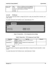
...Advanced PCI Onboard NIC1 Onboard NIC2 Enabled / Disabled Enabled / Disabled Figure 13. PCI Configuration Screen Display Setup Item Onboard NIC1 Onboard NIC2 Table 24. Setup Utility - Intel® Server Board S3000PT Generic USB Flash Drive Auto Floppy Forced FDD Hard Disk CD-ROM If Auto, the USB device less than 530MB will be used to force HDD formatted drive to boot as floppy. Forced FDD option can be enumerated as FDD (e.g., ZIP drive) System BIOS 4.3.2.2.6 PCI Screen The PCI Screen provides fields to configure the power state after certain events.
...Advanced PCI Onboard NIC1 Onboard NIC2 Enabled / Disabled Enabled / Disabled Figure 13. PCI Configuration Screen Display Setup Item Onboard NIC1 Onboard NIC2 Table 24. Setup Utility - Intel® Server Board S3000PT Generic USB Flash Drive Auto Floppy Forced FDD Hard Disk CD-ROM If Auto, the USB device less than 530MB will be used to force HDD formatted drive to boot as floppy. Forced FDD option can be enumerated as FDD (e.g., ZIP drive) System BIOS 4.3.2.2.6 PCI Screen The PCI Screen provides fields to configure the power state after certain events.
Product Specification
Page 49
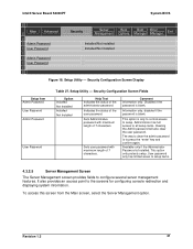
Intel® Server Board S3000PT System BIOS Main Advanced Admin Password User Password Admin Password User Password Security Server Management Boot Options Boot Error Manager Manager Exit Installed/Not installed Installed/Not installed Figure 18. Security Configuration Screen Fields Option Installed Not Installed Installed Not Installed Help Text Indicates the status of the user password. Disabled if the password is only to control access to setup. Administrator has full access to configure several server management features. This option is blank. This...
Intel® Server Board S3000PT System BIOS Main Advanced Admin Password User Password Admin Password User Password Security Server Management Boot Options Boot Error Manager Manager Exit Installed/Not installed Installed/Not installed Figure 18. Security Configuration Screen Fields Option Installed Not Installed Installed Not Installed Help Text Indicates the status of the user password. Disabled if the password is only to control access to setup. Administrator has full access to configure several server management features. This option is blank. This...

Product Specification
Page 51
... to configure the connection options for this item will reset the Intel ® AMT password. Revision 1.3 43 Selecting this feature. See Section 4.3.2.5.1. To access this screen from the Main screen, selec t Server Management | Console Redirection . See Section 4.3.2.5.3. 4.3.2.5.1 View Event Log The View Event Log screen displays all the events that were logged in the Event Log . Intel® Server Board S3000PT System BIOS Setup Item Enter AMTBx Setup Reset Intel® AMT defaults Option Enabled / Disabled Boot to Network...
... to configure the connection options for this item will reset the Intel ® AMT password. Revision 1.3 43 Selecting this feature. See Section 4.3.2.5.1. To access this screen from the Main screen, selec t Server Management | Console Redirection . See Section 4.3.2.5.3. 4.3.2.5.1 View Event Log The View Event Log screen displays all the events that were logged in the Event Log . Intel® Server Board S3000PT System BIOS Setup Item Enter AMTBx Setup Reset Intel® AMT defaults Option Enabled / Disabled Boot to Network...

Product Specification
Page 61
... for manageable attributes that are reported. Revision 1.3 53 WFM allows a server to be supported by the BIOS. Function List Vendor ID 0x8086 0x8086 0x8086 0x8086 Device ID 0x108B/0x108C (V/E) 0x108D 0x108F 0x108E 5.3 Wired For Management (WFM) Wired for Management is required to create a standardized interface for the onboard controllers. Intel® Server Board S3000PT Function Intel® 82573E LAN IDE Serial Port KCS Platform Management Architecture Table 36.
... for manageable attributes that are reported. Revision 1.3 53 WFM allows a server to be supported by the BIOS. Function List Vendor ID 0x8086 0x8086 0x8086 0x8086 Device ID 0x108B/0x108C (V/E) 0x108D 0x108F 0x108E 5.3 Wired For Management (WFM) Wired for Management is required to create a standardized interface for the onboard controllers. Intel® Server Board S3000PT Function Intel® 82573E LAN IDE Serial Port KCS Platform Management Architecture Table 36.
Product Specification
Page 62
... one password is set the user password. Secure boot disabled in secure mode. It is accepted except the password. Platform Management Architecture Intel® Server Board S3000PT TPS Mode Password on boot enabled in BIOS Setup. The server boots normally. The administrator has control over al l fields in BIOS Setup, including the ability to exit ou t of a password can be entered in order to break the password by moving the CMOS Clear jumper into a halt state. Administrator password. A system reset is entered...
... one password is set the user password. Secure boot disabled in secure mode. It is accepted except the password. Platform Management Architecture Intel® Server Board S3000PT TPS Mode Password on boot enabled in BIOS Setup. The server boots normally. The administrator has control over al l fields in BIOS Setup, including the ability to exit ou t of a password can be entered in order to break the password by moving the CMOS Clear jumper into a halt state. Administrator password. A system reset is entered...

Product Specification
Page 63
...-bit ECC error Memory channel B Multi-bit ECC error Memory channel B Single-bit ECC error CMOS battery failure CMOS checksum error CMOS time not set Keyboard not found du ring POST Memory size is decreased compared with last boot Chassis is open Some fields of server management is to clear CMOS. Event List Description Processor thermal trip happened on DIMM channel B. Multi-bit ECC error happened on last boot. Single-bit ECC error happened on DIMM channel A. In addition, error-logging techniques are described and beep codes for errors...
...-bit ECC error Memory channel B Multi-bit ECC error Memory channel B Single-bit ECC error CMOS battery failure CMOS checksum error CMOS time not set Keyboard not found du ring POST Memory size is decreased compared with last boot Chassis is open Some fields of server management is to clear CMOS. Event List Description Processor thermal trip happened on DIMM channel B. Multi-bit ECC error happened on last boot. Single-bit ECC error happened on DIMM channel A. In addition, error-logging techniques are described and beep codes for errors...

Product Specification
Page 70
... boot is enabled. 0xEFh A A A G Reserved for user input 0xE8h A R R OFF Checking password 0xE9h A R R G Entering BIOS setup 0xEAh A R A OFF Flash Update 0xEEh A A A OFF Calling Int 19. The class and subclass fields point to the type of information that is divided into two types: 62 Revision 1.3 The 32-bit numbers include class, subclass, and operation information. Intel® Server Board S3000PT TPS Error Reporting and Handling Checkpoint 0xE1h Diagnostic LED...
... boot is enabled. 0xEFh A A A G Reserved for user input 0xE8h A R R OFF Checking password 0xE9h A R R G Entering BIOS setup 0xEAh A R A OFF Flash Update 0xEEh A A A OFF Calling Int 19. The class and subclass fields point to the type of information that is divided into two types: 62 Revision 1.3 The 32-bit numbers include class, subclass, and operation information. Intel® Server Board S3000PT TPS Error Reporting and Handling Checkpoint 0xE1h Diagnostic LED...
Product Specification
Page 71
... beep codes to press an appro priate key before booting the operating system or entering BIOS Setup. The default value is set to "disabled", the system will enter the error manager and wait for the user to inform users of POST error(s) that are listed as "Pause", the BIOS will boot the operating system without user intervention. If the "POST Error Pause" option is set Configuration cleared by jumper Configuration default loaded Password check failed PCI resource conflict Insufficient memory to "disabled" in the BIOS Setup main menu...
... beep codes to press an appro priate key before booting the operating system or entering BIOS Setup. The default value is set to "disabled", the system will enter the error manager and wait for the user to inform users of POST error(s) that are listed as "Pause", the BIOS will boot the operating system without user intervention. If the "POST Error Pause" option is set Configuration cleared by jumper Configuration default loaded Password check failed PCI resource conflict Insufficient memory to "disabled" in the BIOS Setup main menu...
Product Specification
Page 88
Data Carrier Detect Direct Memory Access Distributed management Task Force Error Correcting Code Electromagnetic Compatibility External Product Specification Extended System Configuration Data Floppy Disk Controller First-In, First-Out Field replaceable unit 1024 MB. Term ACPI ANSI AP ASIC ASR BGA BIOS Byte CMOS DCD DMA DMTF ECC EMC EPS ESCD FDC FIFO FRU GB GPIO GUID Hz HDG I2C IA ICMB IERR IMB IP IRQ...
Data Carrier Detect Direct Memory Access Distributed management Task Force Error Correcting Code Electromagnetic Compatibility External Product Specification Extended System Configuration Data Floppy Disk Controller First-In, First-Out Field replaceable unit 1024 MB. Term ACPI ANSI AP ASIC ASR BGA BIOS Byte CMOS DCD DMA DMTF ECC EMC EPS ESCD FDC FIFO FRU GB GPIO GUID Hz HDG I2C IA ICMB IERR IMB IP IRQ...

Product Specification
Page 92
...; ACPI Static Resource Affinity Table, Version 1.2, http://www.microsoft.com/whdc/hwdev/platform/proc/SRAT.mspx SYSID BIOS Support Interface Requirement Specification , Version 1.2 Intel® Platform Innovation Framework for EFI Firmware Volume Specification , Revision 0.9, Intel Corporation, 2004, ftp://download.intel.com/technology/framework/docs/Fv.pdf Universal Host Controller Interface Design Guid e, http://developer.intel.com/design/USB/UHCI11D.htm Universal Serial Bus Revision 1.1 Specification, http://www.usb...
...; ACPI Static Resource Affinity Table, Version 1.2, http://www.microsoft.com/whdc/hwdev/platform/proc/SRAT.mspx SYSID BIOS Support Interface Requirement Specification , Version 1.2 Intel® Platform Innovation Framework for EFI Firmware Volume Specification , Revision 0.9, Intel Corporation, 2004, ftp://download.intel.com/technology/framework/docs/Fv.pdf Universal Host Controller Interface Design Guid e, http://developer.intel.com/design/USB/UHCI11D.htm Universal Serial Bus Revision 1.1 Specification, http://www.usb...


