
User Guide
Page 2
... intellectual property rights is used outside any of high-density VLSI and power delivery components that chooses not to use in Intel's Terms and Conditions of Sale for use Intel developed server building blocks to consult vendor datasheets and operating parameters to specifications and product descriptions at any other application in which the...
... intellectual property rights is used outside any of high-density VLSI and power delivery components that chooses not to use in Intel's Terms and Conditions of Sale for use Intel developed server building blocks to consult vendor datasheets and operating parameters to specifications and product descriptions at any other application in which the...

User Guide
Page 3
... assist you identify components and their locations. Manual Organization Chapter 1 provides a brief overview of this manual,see http:// www.intel.com/support/motherboards/server/MFS5520VI/. Chapter 2 provides instructions for troubleshooting, upgrading, and repairing compute modules. This manual is written for system technicians who are responsible for adding and replacing components. It provides step-bystep instructions...
... assist you identify components and their locations. Manual Organization Chapter 1 provides a brief overview of this manual,see http:// www.intel.com/support/motherboards/server/MFS5520VI/. Chapter 2 provides instructions for troubleshooting, upgrading, and repairing compute modules. This manual is written for system technicians who are responsible for adding and replacing components. It provides step-bystep instructions...
User Guide
Page 5
...;hren. und Sicherheitshinweise in this document before performing any of the instructions. Beachten Sie hierzu auch die Intel® Server Boards and Server Chassis Safety Information unter http://support.intel.com/support/motherboards/server/sb/cs-010770.htm. Intel® Compute Module MFS5520VI User Guide v Consignes de sécurité Lisez attention toutes les consignes de sécurité...
...;hren. und Sicherheitshinweise in this document before performing any of the instructions. Beachten Sie hierzu auch die Intel® Server Boards and Server Chassis Safety Information unter http://support.intel.com/support/motherboards/server/sb/cs-010770.htm. Intel® Compute Module MFS5520VI User Guide v Consignes de sécurité Lisez attention toutes les consignes de sécurité...
User Guide
Page 6
... jumper pins. Reinstalling enclosure cover: To protect internal components and for proper cooling and airflow, the compute module should maintain or configure the chassis. You must adhere to ensure and maintain compliance with the cover...server product, whether you are using needle nosed pliers to the safety instructions. If your fingertips or with your jumpers do not have a small tab on top that you perform all power from the compute module, uninstall or remove the compute module... parts. We recommend that you can result. vi Intel® Compute Module MFS5520VI User Guide
... jumper pins. Reinstalling enclosure cover: To protect internal components and for proper cooling and airflow, the compute module should maintain or configure the chassis. You must adhere to ensure and maintain compliance with the cover...server product, whether you are using needle nosed pliers to the safety instructions. If your fingertips or with your jumpers do not have a small tab on top that you perform all power from the compute module, uninstall or remove the compute module... parts. We recommend that you can result. vi Intel® Compute Module MFS5520VI User Guide
User Guide
Page 8
...Canada ...101 Europe ...101 In Asia-Pacific region ...102 Japan ...102 Latin America ...102 B Product Regulatory Requirements 105 viii Intel® Compute Module MFS5520VI User Guide Installing and Removing Mezzanine Card 42 Installing the Mezzanine Card 42 Removing a Mezzanine Card 46 Replacing the CMOS Battery... Utility 53 If You Cannot Access Setup 53 General Layout and Navigation 53 Setup Menus ...57 Main ...58 Advanced ...60 Security ...73 Server Management ...76 Boot Options ...81 Boot Manager ...84 Error Manager ...85 Exit ...86 Upgrading the BIOS ...88 Preparing for the Upgrade ...
...Canada ...101 Europe ...101 In Asia-Pacific region ...102 Japan ...102 Latin America ...102 B Product Regulatory Requirements 105 viii Intel® Compute Module MFS5520VI User Guide Installing and Removing Mezzanine Card 42 Installing the Mezzanine Card 42 Removing a Mezzanine Card 46 Replacing the CMOS Battery... Utility 53 If You Cannot Access Setup 53 General Layout and Navigation 53 Setup Menus ...57 Main ...58 Advanced ...60 Security ...73 Server Management ...76 Boot Options ...81 Boot Manager ...84 Error Manager ...85 Exit ...86 Upgrading the BIOS ...88 Preparing for the Upgrade ...
User Guide
Page 11
... Battery Location 50 Intel® Compute Module MFS5520VI User Guide xi Configuration Jumper Locations 5 Figure 5. Front Panel Connectors and Indicators 7 Figure 6. Installing the Processor 22 Figure 15. Reinstalling Processor Air Duct 38 Figure 33. Removing Mezzanine Card 47 Figure 41. Removing the Processor Protective Cover 21 Figure 14. Removing Screws from Server Board 43 Figure...
... Battery Location 50 Intel® Compute Module MFS5520VI User Guide xi Configuration Jumper Locations 5 Figure 5. Front Panel Connectors and Indicators 7 Figure 6. Installing the Processor 22 Figure 15. Reinstalling Processor Air Duct 38 Figure 33. Removing Mezzanine Card 47 Figure 41. Removing the Processor Protective Cover 21 Figure 14. Removing Screws from Server Board 43 Figure...

User Guide
Page 12
... Configuration Screen 73 Figure 54. Boot Manager Screen 84 Figure 60. BIOS Recover Jumper 94 xii Intel® Compute Module MFS5520VI User Guide Advanced Processor Configuration Screen 61 Figure 47. Advanced Serial Port Configuration Screen 68 Figure 51. Server Management - System Information Screen 81 Figure 58. Error Manager Screen 85 Figure 61. Advanced PCI Configuration...
... Configuration Screen 73 Figure 54. Boot Manager Screen 84 Figure 60. BIOS Recover Jumper 94 xii Intel® Compute Module MFS5520VI User Guide Advanced Processor Configuration Screen 61 Figure 47. Advanced Serial Port Configuration Screen 68 Figure 51. Server Management - System Information Screen 81 Figure 58. Error Manager Screen 85 Figure 61. Advanced PCI Configuration...

User Guide
Page 13
... 59 Table 6. Advanced Processor Configuration Details 62 Table 7. USB Configuration Details 70 Table 9. Server Management Screen Details 77 Table 12. Advanced Memory Configuration Screen Details 65 Table 8. Configuration Jumper Description 6 Table 3. Exit Screen Details 86 Intel® Compute Module MFS5520VI User Guide xiii Compute Module Features 3 Table 2. Diagnostic LED Information 7 Table 4. Security Screen Details 75 Table 11...
... 59 Table 6. Advanced Processor Configuration Details 62 Table 7. USB Configuration Details 70 Table 9. Server Management Screen Details 77 Table 12. Advanced Memory Configuration Screen Details 65 Table 8. Configuration Jumper Description 6 Table 3. Exit Screen Details 86 Intel® Compute Module MFS5520VI User Guide xiii Compute Module Features 3 Table 2. Diagnostic LED Information 7 Table 4. Security Screen Details 75 Table 11...
User Guide
Page 17
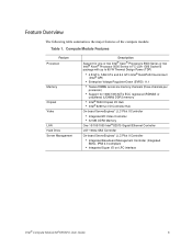
...summarizes the major features of the compute module. Table 1. Compute Module Features Feature Processor Memory Chipset Video LAN Hard Drive Server Management Description Support for one or two Intel® Xeon® Processors 5500 Series or two Intel® Xeon® Processor .../100/1000 Intel® 82575 Gigabit Ethernet Controller LSI* 1064e SAS Controller On-board ServerEngines* LLC Pilot II Controller • Integrated Baseboard Management Controller (Integrated BMC), IPMI 2.0 compliant • Integrated Super I/O on LPC interface Intel® Compute Module MFS5520VI User Guide ...
...summarizes the major features of the compute module. Table 1. Compute Module Features Feature Processor Memory Chipset Video LAN Hard Drive Server Management Description Support for one or two Intel® Xeon® Processors 5500 Series or two Intel® Xeon® Processor .../100/1000 Intel® 82575 Gigabit Ethernet Controller LSI* 1064e SAS Controller On-board ServerEngines* LLC Pilot II Controller • Integrated Baseboard Management Controller (Integrated BMC), IPMI 2.0 compliant • Integrated Super I/O on LPC interface Intel® Compute Module MFS5520VI User Guide ...
User Guide
Page 22
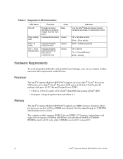
... link On = Link established Blink = Activity Hardware Requirements To avoid integration difficulties and possible board damage, your server compute module must be ECC only, while UDIMMs can be ECC or non-ECC. 8 Intel® Compute Module MFS5520VI User Guide The compute module supports DDR3 1066 and DDR3 1333 memory technologies and supports both registered DIMMs (RDIMMs) and unbuffered DIMMs...
... link On = Link established Blink = Activity Hardware Requirements To avoid integration difficulties and possible board damage, your server compute module must be ECC only, while UDIMMs can be ECC or non-ECC. 8 Intel® Compute Module MFS5520VI User Guide The compute module supports DDR3 1066 and DDR3 1333 memory technologies and supports both registered DIMMs (RDIMMs) and unbuffered DIMMs...
User Guide
Page 24
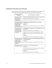
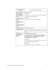
... product or information about the modular server system, including subsystem overviews and mechanical drawings Intel®Compute Module MFS5520VI Quick Start User's Guide Available in the product box or for download at: http://www.intel.com/support/motherboards/server/mfs5520vi/ Intel®Compute Module MFS5520VI Technical Product Specification Available at: http://www.intel.com/support/motherboards/server/mfs5520vi/ Intel®Modular Server System MFSYS25/MFSYS35 Quick Start...
... product or information about the modular server system, including subsystem overviews and mechanical drawings Intel®Compute Module MFS5520VI Quick Start User's Guide Available in the product box or for download at: http://www.intel.com/support/motherboards/server/mfs5520vi/ Intel®Compute Module MFS5520VI Technical Product Specification Available at: http://www.intel.com/support/motherboards/server/mfs5520vi/ Intel®Modular Server System MFSYS25/MFSYS35 Quick Start...
User Guide
Page 25
... to manage your Intel® Modular Server System Intel® Modular Server Control UI The Intel® Management Module integrated management interface for download at : http://www.intel.com/go/servermanagement/ Intel® Compute Module MFS5520VI User Guide 11 For software to the Intel® Modular Server System MFSYS25/MFSYS35 User Guide Available at: http://www.intel.com/support/motherboards/server/mfsys25/ Intel® System Management...
... to manage your Intel® Modular Server System Intel® Modular Server Control UI The Intel® Management Module integrated management interface for download at : http://www.intel.com/go/servermanagement/ Intel® Compute Module MFS5520VI User Guide 11 For software to the Intel® Modular Server System MFSYS25/MFSYS35 User Guide Available at: http://www.intel.com/support/motherboards/server/mfsys25/ Intel® System Management...

User Guide
Page 27
... information at the beginning of this manual and in the appendices. Intel® Compute Module MFS5520VI User Guide 13 Green on the release button located between the two lever handles. For a complete list of installation or removal steps, see the instructions included with your server product, review the safety and ESD information at the beginning...
... information at the beginning of this manual and in the appendices. Intel® Compute Module MFS5520VI User Guide 13 Green on the release button located between the two lever handles. For a complete list of installation or removal steps, see the instructions included with your server product, review the safety and ESD information at the beginning...
User Guide
Page 33
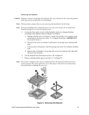
...locations 3 and 4 by giving it by giving each screw two rotations and then stop. d. Loosen the four captive screws on your server board, do not remove the heatsink and spacer over the second processor. 5. Note: The system is shipped with the screw at ... Proceed to protect the socket protective cover. Remove and discard the spacer (see letter "B" in Figure 9) and stop . Removing the Heatsink Intel® Compute Module MFS5520VI User Guide 19 Loosen screws at location 2 and loosen it two rotations in the anticlockwise direction (see letter "A" in Figure 9). 7. Removing ...
...locations 3 and 4 by giving it by giving each screw two rotations and then stop. d. Loosen the four captive screws on your server board, do not remove the heatsink and spacer over the second processor. 5. Note: The system is shipped with the screw at ... Proceed to protect the socket protective cover. Remove and discard the spacer (see letter "B" in Figure 9) and stop . Removing the Heatsink Intel® Compute Module MFS5520VI User Guide 19 Loosen screws at location 2 and loosen it two rotations in the anticlockwise direction (see letter "A" in Figure 9). 7. Removing ...

User Guide
Page 38
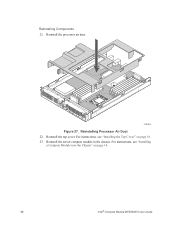
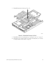
For instructions, see "Installing the Top Cover" on page 14. 24 Intel® Compute Module MFS5520VI User Guide Reinstall the server compute module in the chassis. For instructions, see "Installing a Compute Module into the Chassis" on page 16. 24. Reinstall the top cover. 1 I/O 2 1 2 ID AF003080 Figure 17. Reinstalling Processor Air Duct 23.
For instructions, see "Installing the Top Cover" on page 14. 24 Intel® Compute Module MFS5520VI User Guide Reinstall the server compute module in the chassis. For instructions, see "Installing a Compute Module into the Chassis" on page 16. 24. Reinstall the top cover. 1 I/O 2 1 2 ID AF003080 Figure 17. Reinstalling Processor Air Duct 23.
User Guide
Page 46
Reinstall the top cover. Reinstall the server compute module in the chassis. Reinstalling Processor Air Duct 22. Reinstall the processor air duct. 1 I/O 2 1 2 ID AF003080 Figure 27. For instructions, see "Installing a Compute Module into the Chassis" on page 16. 23. For instructions, see "Installing the Top Cover" on page 14. 32 Intel® Compute Module MFS5520VI User Guide Reinstalling Components 21.
Reinstall the top cover. Reinstall the server compute module in the chassis. Reinstalling Processor Air Duct 22. Reinstall the processor air duct. 1 I/O 2 1 2 ID AF003080 Figure 27. For instructions, see "Installing a Compute Module into the Chassis" on page 16. 23. For instructions, see "Installing the Top Cover" on page 14. 32 Intel® Compute Module MFS5520VI User Guide Reinstalling Components 21.
User Guide
Page 52
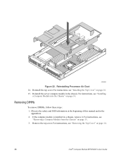
... "Removing a Compute Module from the Chassis" on page 14. 38 Intel® Compute Module MFS5520VI User Guide 1 I/O 2 1 2 ID AF003080 Figure 32. If the compute module is installed in... the appendices. 2. For instructions, see "Removing the Top Cover" on page 13. 3. For instructions, see "Installing the Top Cover" on page 14. Removing DIMMs To remove DIMMs, follow these steps: 1. Reinstalling Processor Air Duct 14. Reinstall the server compute module...
... "Removing a Compute Module from the Chassis" on page 14. 38 Intel® Compute Module MFS5520VI User Guide 1 I/O 2 1 2 ID AF003080 Figure 32. If the compute module is installed in... the appendices. 2. For instructions, see "Removing the Top Cover" on page 13. 3. For instructions, see "Installing the Top Cover" on page 14. Removing DIMMs To remove DIMMs, follow these steps: 1. Reinstalling Processor Air Duct 14. Reinstall the server compute module...
User Guide
Page 55
Reinstall the processor air duct (see "Installing the Top Cover" on page 14. Reinstalling Processor Air Duct 9. For instructions, see Figure 35). 1 I/O 2 1 2 ID AF003080 Figure 35. Intel® Compute Module MFS5520VI User Guide 41 For instructions, see "Installing a Compute Module into the Chassis" on page 16. 10. Reinstall the server compute module in the chassis. Reinstall the top cover. 8.
Reinstall the processor air duct (see "Installing the Top Cover" on page 14. Reinstalling Processor Air Duct 9. For instructions, see Figure 35). 1 I/O 2 1 2 ID AF003080 Figure 35. Intel® Compute Module MFS5520VI User Guide 41 For instructions, see "Installing a Compute Module into the Chassis" on page 16. 10. Reinstall the server compute module in the chassis. Reinstall the top cover. 8.

User Guide
Page 56
... the Chassis" on page 13. 3. For instructions, see "Removing the Top Cover" on the server board. 42 Intel® Compute Module MFS5520VI User Guide Remove the top cover. Locate the mezzanine card connectors on page 14. 4. Holding the mezzanine card by its edges, remove it . Remove the ...
... the Chassis" on page 13. 3. For instructions, see "Removing the Top Cover" on the server board. 42 Intel® Compute Module MFS5520VI User Guide Remove the top cover. Locate the mezzanine card connectors on page 14. 4. Holding the mezzanine card by its edges, remove it . Remove the ...
User Guide
Page 59
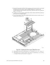
Reinstall the top cover. Intel® Compute Module MFS5520VI User Guide 45 Secure the mezzanine card to position each connector housing on the mezzanine card with the four screws previously removed (see "Installing the ... 14. B Mezzanine Card A 1 I/O 2 1 2 ID AF003083 Figure 38. For instructions, see letter "B" in the chassis. For instructions, see letter "A" in the connectors and resting on the server board (see "Installing a Compute Module into place until it is fully seated in Figure 38). 10. Installing and Securing the Mezzanine Card 12. Reinstall the...
Reinstall the top cover. Intel® Compute Module MFS5520VI User Guide 45 Secure the mezzanine card to position each connector housing on the mezzanine card with the four screws previously removed (see "Installing the ... 14. B Mezzanine Card A 1 I/O 2 1 2 ID AF003083 Figure 38. For instructions, see letter "B" in the chassis. For instructions, see letter "A" in the connectors and resting on the server board (see "Installing a Compute Module into place until it is fully seated in Figure 38). 10. Installing and Securing the Mezzanine Card 12. Reinstall the...

