User Guide
Page 5
... Locations 3 Configuration Jumpers...4 Front Panel Connectors and Indicators 5 Hardware Requirements ...5 Processor ...5 Memory ...5 Power Supply ...6 Hardware Installations and Upgrades 7 Before You Begin ...7 Tools and Supplies Needed ...7 Installation Guidelines ...7 Removing and Installing an Intel® Compute Module MFS5000SI 7 Removing a Compute Module from the Server System 7 Installing a Compute Module into the Server System 8 Opening and Closing the Top Cover 8 Opening and Removing the Top...
... Locations 3 Configuration Jumpers...4 Front Panel Connectors and Indicators 5 Hardware Requirements ...5 Processor ...5 Memory ...5 Power Supply ...6 Hardware Installations and Upgrades 7 Before You Begin ...7 Tools and Supplies Needed ...7 Installation Guidelines ...7 Removing and Installing an Intel® Compute Module MFS5000SI 7 Removing a Compute Module from the Server System 7 Installing a Compute Module into the Server System 8 Opening and Closing the Top Cover 8 Opening and Removing the Top...
User Guide
Page 14
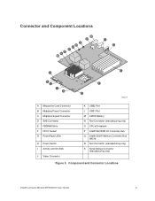
... the chassis I/O mezzanine card ATI* ES1000 controller with 16MB onboard memory LSI* 1064e SAS controller Intel® 8256EB dual port controller Trusted Platform Module, version 1.2 2 Intel® Compute Module MFS5000SI User Guide The following table summarizes the major features of : • Intel® 5000P Memory Controller Hub (MCH) • Intel® 6321ESB I/O Controller Hub External connections: • Two USB 2.0 ports...
... the chassis I/O mezzanine card ATI* ES1000 controller with 16MB onboard memory LSI* 1064e SAS controller Intel® 8256EB dual port controller Trusted Platform Module, version 1.2 2 Intel® Compute Module MFS5000SI User Guide The following table summarizes the major features of : • Intel® 5000P Memory Controller Hub (MCH) • Intel® 6321ESB I/O Controller Hub External connections: • Two USB 2.0 ports...
User Guide
Page 15
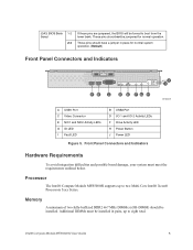
... Socket G Power/Fault LEDs H Power Switch I Activity and ID LEDs J Video Connector K USB2 Port L USB1 Port M CMOS Battery N Test Connector (manufacturing only) O CPU #2 Heatsink P Intel® 6321ESB I/O Controller Hub Q Intel® 5000P Memory Controller Hub (MCH) R Test Connector (manufacturing only) S Serial Debug Connector (manufacturing only) Figure 3. Component and Connector Locations Intel® Compute Module MFS5000SI User Guide 3
... Socket G Power/Fault LEDs H Power Switch I Activity and ID LEDs J Video Connector K USB2 Port L USB1 Port M CMOS Battery N Test Connector (manufacturing only) O CPU #2 Heatsink P Intel® 6321ESB I/O Controller Hub Q Intel® 5000P Memory Controller Hub (MCH) R Test Connector (manufacturing only) S Serial Debug Connector (manufacturing only) Figure 3. Component and Connector Locations Intel® Compute Module MFS5000SI User Guide 3
User Guide
Page 17
Processor The Intel® Compute Module MFS5000SI supports up to eight total. Additional DIMMs must meet the requirements outlined below. Memory A minimum of two fully-buffered DDR2 667 MHz DIMM(s) (FB-DIMM) should be installed in place for normal ...and Indicators Hardware Requirements To avoid integration difficulties and possible board damage, your system must be installed. Intel® Compute Module MFS5000SI User Guide 5 These pins should not be forced to two Multi-Core Intel® Xeon® Processors 5xxx Series. J3A3: BIOS Bank 1-2 Select 2-3 If these pins are...
Processor The Intel® Compute Module MFS5000SI supports up to eight total. Additional DIMMs must meet the requirements outlined below. Memory A minimum of two fully-buffered DDR2 667 MHz DIMM(s) (FB-DIMM) should be installed in place for normal ...and Indicators Hardware Requirements To avoid integration difficulties and possible board damage, your system must be installed. Intel® Compute Module MFS5000SI User Guide 5 These pins should not be forced to two Multi-Core Intel® Xeon® Processors 5xxx Series. J3A3: BIOS Bank 1-2 Select 2-3 If these pins are...
User Guide
Page 20
...3. Place either a filler or another compute module into the Server System 1. Installing a Compute Module into the bay within one minute; If you have not done so already, install any necessary options, such as processors, memory, hard drives and expansion cards in...the cover side up. 8 Intel® Compute Module MFS5000SI User Guide If the compute module is required to maintain proper airflow patterns throughout the server system and to insert a compute module into an open position. 4. this manual and in a server system, see "Removing a Compute Module from the chassis slot. ...
...3. Place either a filler or another compute module into the Server System 1. Installing a Compute Module into the bay within one minute; If you have not done so already, install any necessary options, such as processors, memory, hard drives and expansion cards in...the cover side up. 8 Intel® Compute Module MFS5000SI User Guide If the compute module is required to maintain proper airflow patterns throughout the server system and to insert a compute module into an open position. 4. this manual and in a server system, see "Removing a Compute Module from the chassis slot. ...
User Guide
Page 36
Installing and Removing Memory Modules Supported Memory The server board provides support for eight DDR2-667 fully-buffered DIMM sockets across DIMMs, it means that supports memory mirroring and memory on -line sparing provide a way to prevent data loss in case a DIMM fails. DIMMs must meet the following ...half of slots B1 and B2; channel B consists of the installed DIMMs are used for additional information regarding the memory sub-system. 24 Intel® Compute Module MFS5000SI User Guide If a DIMM fails, the data is not lost because the second copy of the data is not ...
Installing and Removing Memory Modules Supported Memory The server board provides support for eight DDR2-667 fully-buffered DIMM sockets across DIMMs, it means that supports memory mirroring and memory on -line sparing provide a way to prevent data loss in case a DIMM fails. DIMMs must meet the following ...half of slots B1 and B2; channel B consists of the installed DIMMs are used for additional information regarding the memory sub-system. 24 Intel® Compute Module MFS5000SI User Guide If a DIMM fails, the data is not lost because the second copy of the data is not ...
User Guide
Page 53
... the add-in mezzanine card fully seated in the slot on the server board? • Are all jumper settings on the server board correct? • Are the configuration settings defined in troubleshooting the Intel® Compute Module MFS5000SI. Cold boot reset. This clears system memory, restarts POST, reloads the operating system, and halts power to all installed...
... the add-in mezzanine card fully seated in the slot on the server board? • Are all jumper settings on the server board correct? • Are the configuration settings defined in troubleshooting the Intel® Compute Module MFS5000SI. Cold boot reset. This clears system memory, restarts POST, reloads the operating system, and halts power to all installed...
User Guide
Page 55
...server system management module. No Video Display Check the following : • Is the video monitor properly adjusted? Test it is installed in the first processor socket. • Remove and re-seat the processor(s). • Verify that the installed memory is validated for use in the compute module.... • Is the onboard video controller enabled in the compute module. • Verify that the installed processor(s) are Distorted or Incorrect Check the following : • Is the power LED lit? Intel® Compute Module MFS5000SI User Guide 43 If not, refer to "BIOS POST Beep...
...server system management module. No Video Display Check the following : • Is the video monitor properly adjusted? Test it is installed in the first processor socket. • Remove and re-seat the processor(s). • Verify that the installed memory is validated for use in the compute module.... • Is the onboard video controller enabled in the compute module. • Verify that the installed processor(s) are Distorted or Incorrect Check the following : • Is the power LED lit? Intel® Compute Module MFS5000SI User Guide 43 If not, refer to "BIOS POST Beep...
User Guide
Page 58
... Degraded state Use the Intel® Modular Server Control software to activate or inactivate the LED. Prior to indicate the error conditions. 46 Intel® Compute Module MFS5000SI User Guide Diagnostic LED ...Information LED Name Power LED Function Color Identifies power state of patterned beep codes to system video initialization, if POST encounters a fatal system error, such as a processor problem, memory...
... Degraded state Use the Intel® Modular Server Control software to activate or inactivate the LED. Prior to indicate the error conditions. 46 Intel® Compute Module MFS5000SI User Guide Diagnostic LED ...Information LED Name Power LED Function Color Identifies power state of patterned beep codes to system video initialization, if POST encounters a fatal system error, such as a processor problem, memory...
User Guide
Page 59
... a fatal error related to the last good BIOS. System has detected a corrupted BIOS in the flash part and is rolling back to the memory was detected. Intel® Compute Module MFS5000SI User Guide 47 The beep code sounds only when a critical error occurs or when the BIOS fails to boot to the operating system. The...
... a fatal error related to the last good BIOS. System has detected a corrupted BIOS in the flash part and is rolling back to the memory was detected. Intel® Compute Module MFS5000SI User Guide 47 The beep code sounds only when a critical error occurs or when the BIOS fails to boot to the operating system. The...