User Guide
Page 1
Intel® Compute Module MFS5000SI User Guide A Guide for Technically Qualified Assemblers of Intel® Identified Subassemblies/ Products Intel Order Number D90834-005
Intel® Compute Module MFS5000SI User Guide A Guide for Technically Qualified Assemblers of Intel® Identified Subassemblies/ Products Intel Order Number D90834-005
User Guide
Page 3
See also Intel® Server Boards and Server Chassis Safety Information at http://support.intel.com/support/motherboards/server/sb/cs-010770.htm. Consultez Intel® Server Boards and Server Chassis Safety Information sur le site http://support.intel.com/support/motherboards/ server/sb/cs-010770.htm. Intel® Compute Module MFS5000SI User Guide iii Safety Information Important Safety Instructions Read all caution and safety...
See also Intel® Server Boards and Server Chassis Safety Information at http://support.intel.com/support/motherboards/server/sb/cs-010770.htm. Consultez Intel® Server Boards and Server Chassis Safety Information sur le site http://support.intel.com/support/motherboards/ server/sb/cs-010770.htm. Intel® Compute Module MFS5000SI User Guide iii Safety Information Important Safety Instructions Read all caution and safety...
User Guide
Page 4
...care to grip with, but not squeeze, the pliers or other regulatory approvals of the jumper with the cover removed; iv Intel® Compute Module MFS5000SI User Guide We recommend that you perform all procedures in noncompliance with your system when handling parts. Do not touch the ...opening it without the enclosure cover in this guide to ensure and maintain compliance with existing product certifications and approvals. If your server product, whether you open the chassis, add, or remove any other parts. Gripping the wide sides can grip with product regulations...
...care to grip with, but not squeeze, the pliers or other regulatory approvals of the jumper with the cover removed; iv Intel® Compute Module MFS5000SI User Guide We recommend that you perform all procedures in noncompliance with your system when handling parts. Do not touch the ...opening it without the enclosure cover in this guide to ensure and maintain compliance with existing product certifications and approvals. If your server product, whether you open the chassis, add, or remove any other parts. Gripping the wide sides can grip with product regulations...
User Guide
Page 5
... ...5 Processor ...5 Memory ...5 Power Supply ...6 Hardware Installations and Upgrades 7 Before You Begin ...7 Tools and Supplies Needed ...7 Installation Guidelines ...7 Removing and Installing an Intel® Compute Module MFS5000SI 7 Removing a Compute Module from the Server System 7 Installing a Compute Module into the Server System 8 Opening and Closing the Top Cover 8 Opening and Removing the Top Cover 8 Replacing and Closing the Top Cover 10 Installing...
... ...5 Processor ...5 Memory ...5 Power Supply ...6 Hardware Installations and Upgrades 7 Before You Begin ...7 Tools and Supplies Needed ...7 Installation Guidelines ...7 Removing and Installing an Intel® Compute Module MFS5000SI 7 Removing a Compute Module from the Server System 7 Installing a Compute Module into the Server System 8 Opening and Closing the Top Cover 8 Opening and Removing the Top Cover 8 Replacing and Closing the Top Cover 10 Installing...
User Guide
Page 6
... Electro Magnetic Compatibility (EMC) / Harmonic Requirements 57 Product Ecology Requirements 57 Component Regulatory Requirements Needed to a Compute Module 44 Problems with Newly Installed Application Software 45 Problems with Application Software that Previously Functioned Properly 45 Devices are ...61 Server Safety Information ...61 Safety Warnings and Cautions 61 Intended Application Uses ...62 Site Selection ...62 Equipment Handling Practices 62 Power and Electrical Warnings 62 System Access Warnings ...63 Rack Mount Warnings ...64 vi Intel® Compute Module MFS5000SI User ...
... Electro Magnetic Compatibility (EMC) / Harmonic Requirements 57 Product Ecology Requirements 57 Component Regulatory Requirements Needed to a Compute Module 44 Problems with Newly Installed Application Software 45 Problems with Application Software that Previously Functioned Properly 45 Devices are ...61 Server Safety Information ...61 Safety Warnings and Cautions 61 Intended Application Uses ...62 Site Selection ...62 Equipment Handling Practices 62 Power and Electrical Warnings 62 System Access Warnings ...63 Rack Mount Warnings ...64 vi Intel® Compute Module MFS5000SI User ...
User Guide
Page 9
Compute Module Features 2 Table 2. POST Error Beep Codes 47 Intel® Compute Module MFS5000SI User Guide ix Diagnostic LED Information 46 Table 3. List of Tables Table 1.
Compute Module Features 2 Table 2. POST Error Beep Codes 47 Intel® Compute Module MFS5000SI User Guide ix Diagnostic LED Information 46 Table 3. List of Tables Table 1.
User Guide
Page 11
...Protective Shipping Cover 13 Figure 12. Installing Heatsink 15 Figure 16. Removing Processor Air Duct 29 Figure 33. Removing Screws from Server Board 32 Figure 36. Removing Mezzanine Card 37 Figure 41. Configuration Jumper Locations 4 Figure 5. Removing Top Cover 9 Figure...Socket Lever 21 Figure 26. Reinstalling Processor Air Duct 31 Figure 35. Securing Mezzanine Card to Standoffs 35 Figure 39. Intel® Compute Module MFS5000SI 1 Figure 2. Installing Standoffs for Mezzanine Card 33 Figure 37. Removing Processor Air Duct 26 Figure 30. Component and ...
...Protective Shipping Cover 13 Figure 12. Installing Heatsink 15 Figure 16. Removing Processor Air Duct 29 Figure 33. Removing Screws from Server Board 32 Figure 36. Removing Mezzanine Card 37 Figure 41. Configuration Jumper Locations 4 Figure 5. Removing Top Cover 9 Figure...Socket Lever 21 Figure 26. Reinstalling Processor Air Duct 31 Figure 35. Securing Mezzanine Card to Standoffs 35 Figure 39. Intel® Compute Module MFS5000SI 1 Figure 2. Installing Standoffs for Mezzanine Card 33 Figure 37. Removing Processor Air Duct 26 Figure 30. Component and ...
User Guide
Page 13
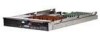
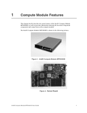
1 Compute Module Features This chapter briefly describes the main features of the Intel® Compute Module MFS5000SI, as well as provides illustrations showing the location of important components and connections on the compute module. Intel® Compute Module MFS5000SI Figure 2. Server Board Intel® Compute Module MFS5000SI User Guide 1 The Intel® Compute Module MFS5000SI is shown in the following pictures. Figure 1.
1 Compute Module Features This chapter briefly describes the main features of the Intel® Compute Module MFS5000SI, as well as provides illustrations showing the location of important components and connections on the compute module. Intel® Compute Module MFS5000SI Figure 2. Server Board Intel® Compute Module MFS5000SI User Guide 1 The Intel® Compute Module MFS5000SI is shown in the following pictures. Figure 1.
User Guide
Page 14
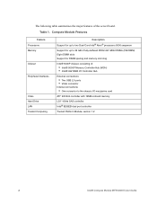
... 16MB onboard memory LSI* 1064e SAS controller Intel® 8256EB dual port controller Trusted Platform Module, version 1.2 2 Intel® Compute Module MFS5000SI User Guide Table 1. Compute Module Features Feature Processors Memory Chipset Peripheral Interfaces Video Hard Drive LAN Trusted Computing Description Support for up to two Dual-Core Intel® Xeon® processors 5000 sequence Support...connector to 32 GB of fully-buffered DDR2 667-MHz DIMMs (FB-DIMM) Eight DIMM slots Support for DIMM sparing and memory mirroring Intel® 5000P chipset, consisting of the server board.
... 16MB onboard memory LSI* 1064e SAS controller Intel® 8256EB dual port controller Trusted Platform Module, version 1.2 2 Intel® Compute Module MFS5000SI User Guide Table 1. Compute Module Features Feature Processors Memory Chipset Peripheral Interfaces Video Hard Drive LAN Trusted Computing Description Support for up to two Dual-Core Intel® Xeon® processors 5000 sequence Support...connector to 32 GB of fully-buffered DDR2 667-MHz DIMMs (FB-DIMM) Eight DIMM slots Support for DIMM sparing and memory mirroring Intel® 5000P chipset, consisting of the server board.
User Guide
Page 15
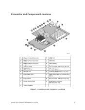
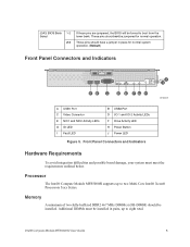
... Intel® Compute Module MFS5000SI User Guide 3 Connector and Component Locations S R Q P O N M B A C D E L K J I H F G AF002219 A Mezzanine Card Connector B Midplane Power Connector C Midplane Signal Connector D SAS Connector E FBDIMM Slots F CPU1 Socket G Power/Fault LEDs H Power Switch I Activity and ID LEDs J Video Connector K USB2 Port L USB1 Port M CMOS Battery N Test Connector (manufacturing only) O CPU #2 Heatsink P Intel® 6321ESB I/O Controller Hub Q Intel...
... Intel® Compute Module MFS5000SI User Guide 3 Connector and Component Locations S R Q P O N M B A C D E L K J I H F G AF002219 A Mezzanine Card Connector B Midplane Power Connector C Midplane Signal Connector D SAS Connector E FBDIMM Slots F CPU1 Socket G Power/Fault LEDs H Power Switch I Activity and ID LEDs J Video Connector K USB2 Port L USB1 Port M CMOS Battery N Test Connector (manufacturing only) O CPU #2 Heatsink P Intel® 6321ESB I/O Controller Hub Q Intel...
User Guide
Page 16
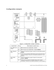
... have a jumper in place for normal system operation (Default) If these pins are jumpered, administrator and user passwords will be jumpered for normal operation. 4 Intel® Compute Module MFS5000SI User Guide Configuration Jumpers Fi BIOS Bank Select 32 Default BOOT FROM EMERGENCY BIOS IMAGE J3A3 PASSWORD CLR Default 2 CLEAR 3 PASSWORD J4A1 BMC Force Update...
... have a jumper in place for normal system operation (Default) If these pins are jumpered, administrator and user passwords will be jumpered for normal operation. 4 Intel® Compute Module MFS5000SI User Guide Configuration Jumpers Fi BIOS Bank Select 32 Default BOOT FROM EMERGENCY BIOS IMAGE J3A3 PASSWORD CLR Default 2 CLEAR 3 PASSWORD J4A1 BMC Force Update...
User Guide
Page 17
... D I/O 1 and I/O 2 Activity LEDs F Drive Activity LED H Power Button J Power LED Figure 5. Processor The Intel® Compute Module MFS5000SI supports up to boot from the lower bank. Intel® Compute Module MFS5000SI User Guide 5 These pins should have a jumper in pairs, up to two Multi-Core Intel® Xeon® Processors 5xxx Series. J3A3: BIOS Bank 1-2 Select 2-3 If these pins are...
... D I/O 1 and I/O 2 Activity LEDs F Drive Activity LED H Power Button J Power LED Figure 5. Processor The Intel® Compute Module MFS5000SI supports up to boot from the lower bank. Intel® Compute Module MFS5000SI User Guide 5 These pins should have a jumper in pairs, up to two Multi-Core Intel® Xeon® Processors 5xxx Series. J3A3: BIOS Bank 1-2 Select 2-3 If these pins are...
User Guide
Page 18
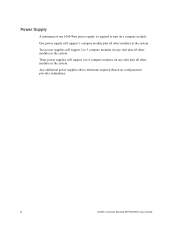
One power supply will support 1 compute module plus all other modules in the system. Two power supplies will support 4 to 6 compute modules (in any slot) plus all other modules in the system. Power Supply A minimum of one 1000-Watt power supply is required to turn on configuration) provides redundancy. 6 Intel® Compute Module MFS5000SI User Guide Any additional power supplies above minimum required (based on a compute module. Three power supplies will support 2 to 3 compute modules (in any slot) plus all other modules in the system.
One power supply will support 1 compute module plus all other modules in the system. Two power supplies will support 4 to 6 compute modules (in any slot) plus all other modules in the system. Power Supply A minimum of one 1000-Watt power supply is required to turn on configuration) provides redundancy. 6 Intel® Compute Module MFS5000SI User Guide Any additional power supplies above minimum required (based on a compute module. Three power supplies will support 2 to 3 compute modules (in any slot) plus all other modules in the system.
User Guide
Page 19
... to shut down the operating system and turn off the compute module. Blue on a component indicates that the component may be hot-swapped. Remove the compute module from the Server System 1. If the compute module is operating, shut down the operating system and power it from the server. 4. Intel® Compute Module MFS5000SI User Guide 7 2 Hardware Installations and Upgrades Before You Begin...
... to shut down the operating system and turn off the compute module. Blue on a component indicates that the component may be hot-swapped. Remove the compute module from the Server System 1. If the compute module is operating, shut down the operating system and power it from the server. 4. Intel® Compute Module MFS5000SI User Guide 7 2 Hardware Installations and Upgrades Before You Begin...
User Guide
Page 20
... server system and to insert a compute module into the Server System 1. do not attempt to ensure proper system cooling. Close the retention lever handles on a flat, non-conductive surface, with the cover side up. 8 Intel® Compute Module MFS5000SI User Guide Insert the compute module into the bay within one minute; Carefully lay the compute module down on the front of the compute module...
... server system and to insert a compute module into the Server System 1. do not attempt to ensure proper system cooling. Close the retention lever handles on a flat, non-conductive surface, with the cover side up. 8 Intel® Compute Module MFS5000SI User Guide Insert the compute module into the bay within one minute; Carefully lay the compute module down on the front of the compute module...
User Guide
Page 21
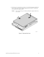
Press the top cover release button (see letter "A" in the following figure) and slide the top cover back, away from the compute module bezel (see letter "B"). B A 1 I/O 2 1 2 ID Figure 6. Lift the top cover up and off the compute module. Caution: Always replace the top cover before installing the compute module into a server system. Removing Top Cover AF002402 Intel® Compute Module MFS5000SI User Guide 9 4.
Press the top cover release button (see letter "A" in the following figure) and slide the top cover back, away from the compute module bezel (see letter "B"). B A 1 I/O 2 1 2 ID Figure 6. Lift the top cover up and off the compute module. Caution: Always replace the top cover before installing the compute module into a server system. Removing Top Cover AF002402 Intel® Compute Module MFS5000SI User Guide 9 4.
User Guide
Page 22
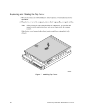
Observe the safety and ESD information at the beginning of this manual and in the appendices 2. Place the top cover on the compute module so that no loose tools or parts are inside the compute module. Replacing and Closing the Top Cover 1. Note: Before closing the top cover, check that all components are installed and seated correctly and that it engages the cover guide notches. Slide the top cover forward to the closed position until the retention latch fully engages. 1 I/O 2 1 2 ID Figure 7. Installing Top Cover AF002403 10 Intel® Compute Module MFS5000SI User Guide
Observe the safety and ESD information at the beginning of this manual and in the appendices 2. Place the top cover on the compute module so that no loose tools or parts are inside the compute module. Replacing and Closing the Top Cover 1. Note: Before closing the top cover, check that all components are installed and seated correctly and that it engages the cover guide notches. Slide the top cover forward to the closed position until the retention latch fully engages. 1 I/O 2 1 2 ID Figure 7. Installing Top Cover AF002403 10 Intel® Compute Module MFS5000SI User Guide
User Guide
Page 23
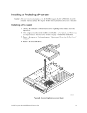
...and in the Intel® Compute Module MFS5000SI should be installed. For instructions, see "Removing a Compute Module from the Server System" on page 8. 4. Remove the processor air duct. 1 I/O 2 1 2 ID Figure 8. Removing Processor Air Duct Intel® Compute Module MFS5000SI User Guide AF002404... 11 Remove the top cover. You may damage the compute module if an inappropriate processor is installed in a server system, see "Opening and Removing the Top Cover" on page...
...and in the Intel® Compute Module MFS5000SI should be installed. For instructions, see "Removing a Compute Module from the Server System" on page 8. 4. Remove the processor air duct. 1 I/O 2 1 2 ID Figure 8. Removing Processor Air Duct Intel® Compute Module MFS5000SI User Guide AF002404... 11 Remove the top cover. You may damage the compute module if an inappropriate processor is installed in a server system, see "Opening and Removing the Top Cover" on page...
User Guide
Page 24
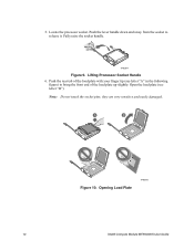
Note: Do not touch the socket pins; A B Figure 10. Push the rear tab of the load plate up slightly. Opening Load Plate TP02075 12 Intel® Compute Module MFS5000SI User Guide TP02074 Figure 9. Push the lever handle down and away from the socket to bring the front end of the load plate with your finger tip (see letter "B"). they are very sensitive and easily damaged. 5. Lifting Processor Socket Handle 6. Fully raise the socket handle. Locate the processor socket. Open the load plate (see letter "A" in the following figure) to release it.
Note: Do not touch the socket pins; A B Figure 10. Push the rear tab of the load plate up slightly. Opening Load Plate TP02075 12 Intel® Compute Module MFS5000SI User Guide TP02074 Figure 9. Push the lever handle down and away from the socket to bring the front end of the load plate with your finger tip (see letter "B"). they are very sensitive and easily damaged. 5. Lifting Processor Socket Handle 6. Fully raise the socket handle. Locate the processor socket. Open the load plate (see letter "A" in the following figure) to release it.
User Guide
Page 25
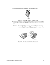
... may damage the socket pins if installed improperly. DO NOT DROP processor into socket. A B AF002223 Figure 12. AF002222 Figure 11. Orienting and Installing Processor Intel® Compute Module MFS5000SI User Guide 13 7. Orient the processor with socket opening before installation. Removing Protective Shipping Cover 8. Caution: The underside of the processor has components that the...
... may damage the socket pins if installed improperly. DO NOT DROP processor into socket. A B AF002223 Figure 12. AF002222 Figure 11. Orienting and Installing Processor Intel® Compute Module MFS5000SI User Guide 13 7. Orient the processor with socket opening before installation. Removing Protective Shipping Cover 8. Caution: The underside of the processor has components that the...