
Mechanical Design Guidelines
Page 4
...43 5.2.1.2 Shock Test Procedure 44 5.2.2 Power Cycling 45 5.2.3 Recommended BIOS/CPU/Memory Test Procedures 46 5.3 Material and Recycling Requirements 46 5.4 Safety Requirements 47 5.5 Geometric Envelope for Intel® Reference BTX Thermal Module Assembly ......47 5.6 Preload and TMA ...55 6.3.1.2 Shock Test Procedure 56 6.3.2 Power Cycling 57 6.3.3 Recommended BIOS/CPU/Memory Test Procedures 58 6.4 Material and Recycling Requirements 58 6.5 Safety Requirements 59 6.6 Geometric Envelope for Intel® Reference ATX Thermal Mechanical Design.....59 6.7 Reference Attach Mechanism 60...
...43 5.2.1.2 Shock Test Procedure 44 5.2.2 Power Cycling 45 5.2.3 Recommended BIOS/CPU/Memory Test Procedures 46 5.3 Material and Recycling Requirements 46 5.4 Safety Requirements 47 5.5 Geometric Envelope for Intel® Reference BTX Thermal Module Assembly ......47 5.6 Preload and TMA ...55 6.3.1.2 Shock Test Procedure 56 6.3.2 Power Cycling 57 6.3.3 Recommended BIOS/CPU/Memory Test Procedures 58 6.4 Material and Recycling Requirements 58 6.5 Safety Requirements 59 6.6 Geometric Envelope for Intel® Reference ATX Thermal Mechanical Design.....59 6.7 Reference Attach Mechanism 60...
Mechanical Design Guidelines
Page 45
...this test. Thermal and Mechanical Design Guidelines 45 The stress test should be followed by the thermal profile at 45º C. Successful BIOS/Processor/memory test of heatsink or heatsink attach mechanism. 5. No visible physical damage to Section 6.3.3). A Thermal Test Vehicle is used for the ...case temperature from room temperature (~23º C) to the maximum case temperature defined by a visual inspection and then BIOS/CPU/Memory test. 5.2.1.2.2 Post-Test Pass Criteria The post-test pass criteria are: 1. No signs of physical damage on motherboard surface due to...
...this test. Thermal and Mechanical Design Guidelines 45 The stress test should be followed by the thermal profile at 45º C. Successful BIOS/Processor/memory test of heatsink or heatsink attach mechanism. 5. No visible physical damage to Section 6.3.3). A Thermal Test Vehicle is used for the ...case temperature from room temperature (~23º C) to the maximum case temperature defined by a visual inspection and then BIOS/CPU/Memory test. 5.2.1.2.2 Post-Test Pass Criteria The post-test pass criteria are: 1. No signs of physical damage on motherboard surface due to...

Mechanical Design Guidelines
Page 46
...Extended (BTX) Thermal/Mechanical Design Information 5.2.3 5.3 Recommended BIOS/CPU/Memory Test Procedures This test is that the system under test shall successfully complete the checking of BIOS, basic processor functions and memory, without any battery of tests prior to determine..., and many hydrocarbons. Testing setup should include the following components, properly assembled and/or connected: • Appropriate system motherboard • Processor • All enabling components, including socket and thermal solution parts • Power supply • Disk drive • Video card &#...
...Extended (BTX) Thermal/Mechanical Design Information 5.2.3 5.3 Recommended BIOS/CPU/Memory Test Procedures This test is that the system under test shall successfully complete the checking of BIOS, basic processor functions and memory, without any battery of tests prior to determine..., and many hydrocarbons. Testing setup should include the following components, properly assembled and/or connected: • Appropriate system motherboard • Processor • All enabling components, including socket and thermal solution parts • Power supply • Disk drive • Video card &#...
Mechanical Design Guidelines
Page 57
...followed by the thermal profile at 45 ºC. No visible tilt of the heatsink with a visual inspection after assembly, and BIOS/CPU/Memory test (refer to the mechanical shock & vibration test, the units under test should always start with components (that is, ... significant physical damage to TIM degradation is evaluated using power cycling testing. Heatsink remains seated and its attach mechanism. 4. Successful BIOS/Processor/memory test of heatsink or heatsink attach mechanism. 5. The test sequence should be met. 6.3.2 Power Cycling Thermal performance degradation due to...
...followed by the thermal profile at 45 ºC. No visible tilt of the heatsink with a visual inspection after assembly, and BIOS/CPU/Memory test (refer to the mechanical shock & vibration test, the units under test should always start with components (that is, ... significant physical damage to TIM degradation is evaluated using power cycling testing. Heatsink remains seated and its attach mechanism. 4. Successful BIOS/Processor/memory test of heatsink or heatsink attach mechanism. 5. The test sequence should be met. 6.3.2 Power Cycling Thermal performance degradation due to...

Mechanical Design Guidelines
Page 58
...resistant to fungal growth. Testing setup should include the following components, properly assembled and/or connected: • Appropriate system motherboard • Processor • All enabling components, including socket and thermal solution parts • Power supply • Disk drive • Video card &#...mechanical enabling components assembled. If materials are susceptible to fungal growth. ATX Thermal/Mechanical Design Information 6.3.3 6.4 Recommended BIOS/CPU/Memory Test Procedures This test is that has not been exposed to any errors. The test shall be performed to...
...resistant to fungal growth. Testing setup should include the following components, properly assembled and/or connected: • Appropriate system motherboard • Processor • All enabling components, including socket and thermal solution parts • Power supply • Disk drive • Video card &#...mechanical enabling components assembled. If materials are susceptible to fungal growth. ATX Thermal/Mechanical Design Information 6.3.3 6.4 Recommended BIOS/CPU/Memory Test Procedures This test is that has not been exposed to any errors. The test shall be performed to...

Mechanical Design Guidelines
Page 110
... Y14.5M-1994 DIMENSIONS ARE IN MILLIMETERS DESIGNED BY DATE CHECKED BY DATE DEPARTMENT R 2200 MISSION COLLEGE BLVD. DIMENSIONS ARE IN MILLIMETERS. 2 GEOMETRIC CENTER OF CPU PACKAGE / SOCKET HOUSING CAVITY. 3. BOX 58119 A SANTA CLARA, CA 95052-8119 TITLE THIRD ANGLE PROJECTION APPROVED BY DATE LGA775 microATX APPROVED BY DATE MATERIAL: N/A FINISH...
... Y14.5M-1994 DIMENSIONS ARE IN MILLIMETERS DESIGNED BY DATE CHECKED BY DATE DEPARTMENT R 2200 MISSION COLLEGE BLVD. DIMENSIONS ARE IN MILLIMETERS. 2 GEOMETRIC CENTER OF CPU PACKAGE / SOCKET HOUSING CAVITY. 3. BOX 58119 A SANTA CLARA, CA 95052-8119 TITLE THIRD ANGLE PROJECTION APPROVED BY DATE LGA775 microATX APPROVED BY DATE MATERIAL: N/A FINISH...
Mechanical Design Guidelines
Page 112
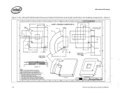
...16.00 ) C SOCKET BALL 1 ( 55.58 ) B 5.80 SECTION A-A 3.80 NOTES: 1 SOCKET CENTER PLANES ARE REFERENCED FROM GEOMETRIC CENTER OF SOCKET HOUSING CAVITY FOR CPU PACKAGE (ALIGNES WITH DATUM REFERENCE GIVEN FOR BOARD COMPONENT KEEP-INS). SOCKET DEVELOPERS SHALL DESIGN TO THE INSIDE VOLUME. 8 7 6 5 TOP SIDE VIEW 4 DEPARTMENT TMD 3 ..., WITHOUT THE PRI 49.00 24.50 19.25 3.00 A 6 5 4 DISCLOSED IN CONFIDENCE AND ITS CONT ENTS OR WRITTEN CONSENT OF INTEL CORPORAT ION. 2X SOCKET & PROCESSOR VOLUMETRIC KEEP-IN 45 X 3.00 29.00 R49.44 R33.29 ( 37.60 ) 14.10 6.60 2.75 C 2.50 45 X ...
...16.00 ) C SOCKET BALL 1 ( 55.58 ) B 5.80 SECTION A-A 3.80 NOTES: 1 SOCKET CENTER PLANES ARE REFERENCED FROM GEOMETRIC CENTER OF SOCKET HOUSING CAVITY FOR CPU PACKAGE (ALIGNES WITH DATUM REFERENCE GIVEN FOR BOARD COMPONENT KEEP-INS). SOCKET DEVELOPERS SHALL DESIGN TO THE INSIDE VOLUME. 8 7 6 5 TOP SIDE VIEW 4 DEPARTMENT TMD 3 ..., WITHOUT THE PRI 49.00 24.50 19.25 3.00 A 6 5 4 DISCLOSED IN CONFIDENCE AND ITS CONT ENTS OR WRITTEN CONSENT OF INTEL CORPORAT ION. 2X SOCKET & PROCESSOR VOLUMETRIC KEEP-IN 45 X 3.00 29.00 R49.44 R33.29 ( 37.60 ) 14.10 6.60 2.75 C 2.50 45 X ...

