Mechanical Design Guidelines
Page 2
... or quantitative increases in clock, speed, cache, FSB, or other intellectual property rights that relate to deviate from published specifications. The Intel® Core™2 Duo processor E8000, E7000 series and Intel® Pentium® Dual-Core processor E6000, E5000 series and Intel® Celeron® processor E3000 series components may be claimed as errata, which have an order number and are referenced in this information...
... or quantitative increases in clock, speed, cache, FSB, or other intellectual property rights that relate to deviate from published specifications. The Intel® Core™2 Duo processor E8000, E7000 series and Intel® Pentium® Dual-Core processor E6000, E5000 series and Intel® Celeron® processor E3000 series components may be claimed as errata, which have an order number and are referenced in this information...
Mechanical Design Guidelines
Page 8
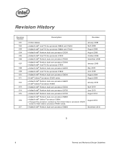
...174; Core™2 Duo processor E7600 • Added Intel® Pentium dual-core processor E6500 • Intel® Celeron® processor E3x00 series • Added Intel® Pentium dual-core processor E6600 • Intel® Celeron® processor E3400 • Added Intel® Pentium dual-core processor E5500 • Added Intel® Pentium dual-core processor E6700 • Added Intel® Pentium dual-core processor E5700 • Added Intel® Pentium dual-core processor E6800 • Added Intel® Celeron® processor E3500 • Changed the processor numbering...
...174; Core™2 Duo processor E7600 • Added Intel® Pentium dual-core processor E6500 • Intel® Celeron® processor E3x00 series • Added Intel® Pentium dual-core processor E6600 • Intel® Celeron® processor E3400 • Added Intel® Pentium dual-core processor E5500 • Added Intel® Pentium dual-core processor E6700 • Added Intel® Pentium dual-core processor E5700 • Added Intel® Pentium dual-core processor E6800 • Added Intel® Celeron® processor E3500 • Changed the processor numbering...
Mechanical Design Guidelines
Page 9
... using the Intel® Core™2 Duo processor E8000, E7000 series, Intel® Pentium® dual-core processor E6000, E5000 series, and Intel® Celeron® processor E3000 series. The processor temperature depends in particular on system design to ensure that thermal design requirements are maintained within the system. The concepts given in this temperature range, a component is expected to meet its specified performance. All of these...
... using the Intel® Core™2 Duo processor E8000, E7000 series, Intel® Pentium® dual-core processor E6000, E5000 series, and Intel® Celeron® processor E3000 series. The processor temperature depends in particular on system design to ensure that thermal design requirements are maintained within the system. The concepts given in this temperature range, a component is expected to meet its specified performance. All of these...
Mechanical Design Guidelines
Page 10
... cache applies to Intel® Pentium® dual-core processor E6800, E6700, E6600, E6500, and E6300 • Intel® Celeron® processor E3000 series with 1 MB cache applies to the Intel® Celeron® processor E3500, E3400, E3300, and E3200 In this document when a reference is made to "the datasheet", the reader should refer to the Intel® Core™2 Duo Processor E8000 and E7000 Series Datasheet, Intel® Pentium® Dual-Core Processor E6000...
... cache applies to Intel® Pentium® dual-core processor E6800, E6700, E6600, E6500, and E6300 • Intel® Celeron® processor E3000 series with 1 MB cache applies to the Intel® Celeron® processor E3500, E3400, E3300, and E3200 In this document when a reference is made to "the datasheet", the reader should refer to the Intel® Core™2 Duo Processor E8000 and E7000 Series Datasheet, Intel® Pentium® Dual-Core Processor E6000...

Mechanical Design Guidelines
Page 11
.../ Definition of thermal solution performance using total package power. Material and concepts available in the following documents may be beneficial when reading this document. Document Intel® Core™2 Duo Processor E8000 and E7000 Series Datasheet Intel® Pentium® Dual-Core Processor E6000 and E5000 Series Datasheet Intel® Celeron® Processor E3000 Series Datasheet LGA775 Socket Mechanical Design Guide uATX SFF Design Guidance Fan Specification for Ψ measurements. Introduction...
.../ Definition of thermal solution performance using total package power. Material and concepts available in the following documents may be beneficial when reading this document. Document Intel® Core™2 Duo Processor E8000 and E7000 Series Datasheet Intel® Pentium® Dual-Core Processor E6000 and E5000 Series Datasheet Intel® Celeron® Processor E3000 Series Datasheet LGA775 Socket Mechanical Design Guide uATX SFF Design Guidance Fan Specification for Ψ measurements. Introduction...

Mechanical Design Guidelines
Page 14
... static load is necessary to ensure mechanical performance, it should be the interface for heatsink removal operations. 14 Thermal and Mechanical Design Guidelines Refer to the LGA775 Socket Mechanical Design Guide for the thermal solution of interest should not be compared to the processor datasheet specification. After actuation of the socket load plate, the seating plane of the...
... static load is necessary to ensure mechanical performance, it should be the interface for heatsink removal operations. 14 Thermal and Mechanical Design Guidelines Refer to the LGA775 Socket Mechanical Design Guide for the thermal solution of interest should not be compared to the processor datasheet specification. After actuation of the socket load plate, the seating plane of the...

Mechanical Design Guidelines
Page 16
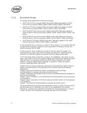
... installation and actuation to avoid scratching the motherboard. 2.2 2.2.1 Thermal Requirements Refer to the datasheet for a 37.5 mm x 37.5 mm [1.474 in x 1.474 in] 775-Land LGA processor package with the temperature reported by the digital thermal sensor and a fan speed control method. The Thermal Profile defines the maximum case temperature as heat through the IHS. Designing to these specifications...
... installation and actuation to avoid scratching the motherboard. 2.2 2.2.1 Thermal Requirements Refer to the datasheet for a 37.5 mm x 37.5 mm [1.474 in x 1.474 in] 775-Land LGA processor package with the temperature reported by the digital thermal sensor and a fan speed control method. The Thermal Profile defines the maximum case temperature as heat through the IHS. Designing to these specifications...
Mechanical Design Guidelines
Page 17
... °C + 5°C = 40 °C. For BTX platforms, a front-to-back cooling design equivalent to Intel BTX TMA Type II reference design (see Chapter 6) should be used in thermal solution performance of 35 °C + 0.5 °C = 35.5 °C. Refer to manage the processor TDP at an inlet temperature of Intel Core™2 Duo processor E8000 series with the available chassis solutions.
... °C + 5°C = 40 °C. For BTX platforms, a front-to-back cooling design equivalent to Intel BTX TMA Type II reference design (see Chapter 6) should be used in thermal solution performance of 35 °C + 0.5 °C = 35.5 °C. Refer to manage the processor TDP at an inlet temperature of Intel Core™2 Duo processor E8000 series with the available chassis solutions.
Mechanical Design Guidelines
Page 18
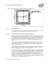
... thermal profiles for the Intel Core™2 Duo processor E8000 series with 6 MB cache, Intel Core™2 Duo processor E7000 series with 3 MB cache, and Intel Pentium dual-core processor E6000 and E5000 series with 2 MB cache, and Intel Celeron processor E3000 series with 1 MB cache are defined such that there is relative to the Thermal Control Circuit (TCC) activation set point which will be seen as larger negative number) of factors.
... thermal profiles for the Intel Core™2 Duo processor E8000 series with 6 MB cache, Intel Core™2 Duo processor E7000 series with 3 MB cache, and Intel Pentium dual-core processor E6000 and E5000 series with 2 MB cache, and Intel Celeron processor E3000 series with 1 MB cache are defined such that there is relative to the Thermal Control Circuit (TCC) activation set point which will be seen as larger negative number) of factors.
Mechanical Design Guidelines
Page 22
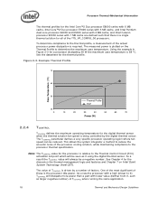
... system components out of the processor fan heatsink. The following tables show the TA requirements for Intel® Core™2 Duo Processor E8000, E7000 Series, Intel® Pentium® Dual-Core Processor E6000, E5000 Series, and Intel® Celeron® Processor E3000 Series Heatsink Inlet Temperature 40 °C NOTE: 1. Heatsink Inlet Temperature of the thermally advantaged chassis (refer to meet specific system design constraints. The number, size and relative position of...
... system components out of the processor fan heatsink. The following tables show the TA requirements for Intel® Core™2 Duo Processor E8000, E7000 Series, Intel® Pentium® Dual-Core Processor E6000, E5000 Series, and Intel® Celeron® Processor E3000 Series Heatsink Inlet Temperature 40 °C NOTE: 1. Heatsink Inlet Temperature of the thermally advantaged chassis (refer to meet specific system design constraints. The number, size and relative position of...
Mechanical Design Guidelines
Page 32
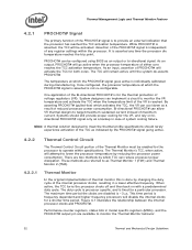
... (VR). This time period is frequency dependent and higher frequency processors will go active when the processor temperature of the VR is for a shorter time period. Performance counter registers, status bits in model specific registers (MSRs), and the PROCHOT# output pin are disabled is... any register settings within specifications. The TCC will attempt to monitor the VR temperature and activate the TCC when the temperature limit of either core reaches the TCC activation temperature. Assertion of the PROCHOT# signal is done by reducing the processor power consumption....
... (VR). This time period is frequency dependent and higher frequency processors will go active when the processor temperature of the VR is for a shorter time period. Performance counter registers, status bits in model specific registers (MSRs), and the PROCHOT# output pin are disabled is... any register settings within specifications. The TCC will attempt to monitor the VR temperature and activate the TCC when the temperature limit of either core reaches the TCC activation temperature. Assertion of the PROCHOT# signal is done by reducing the processor power consumption....
Mechanical Design Guidelines
Page 33
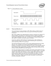
...processor and limiting the processor temperature. When the TCC is , 12.5 mV steps). Each step will be one VID table entry (that is activated, the processor automatically transitions to execute instructions during the voltage transition. TM2 provides an efficient means of a specific operating frequency and voltage. Edge-triggered interrupts will be necessary to transition through multiple VID codes to service... new VID code to the voltage regulator. During the voltage change, it will transition to the new core operating voltage by dropping the bus-to-core multiplier to support ...
...processor and limiting the processor temperature. When the TCC is , 12.5 mV steps). Each step will be one VID table entry (that is activated, the processor automatically transitions to execute instructions during the voltage transition. TM2 provides an efficient means of a specific operating frequency and voltage. Edge-triggered interrupts will be necessary to transition through multiple VID codes to service... new VID code to the voltage regulator. During the voltage change, it will transition to the new core operating voltage by dropping the bus-to-core multiplier to support ...
Mechanical Design Guidelines
Page 34
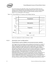
... internal interrupt which would initiate an OEM supplied interrupt service routine. 34 Thermal and Mechanical Design Guidelines Enabling the Thermal Control Circuit allows the processor to attempt to the datasheet for special software drivers or interrupt handling routines. Thermal Monitor 2 Frequency and Voltage Ordering T TM2 Temperature 4.2.4 f MAX f TM2 VID VID TM2 PROCHOT# Frequency VID Time Refer...
... internal interrupt which would initiate an OEM supplied interrupt service routine. 34 Thermal and Mechanical Design Guidelines Enabling the Thermal Control Circuit allows the processor to attempt to the datasheet for special software drivers or interrupt handling routines. Thermal Monitor 2 Frequency and Voltage Ordering T TM2 Temperature 4.2.4 f MAX f TM2 VID VID TM2 PROCHOT# Frequency VID Time Refer...
Mechanical Design Guidelines
Page 37
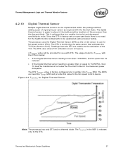
Since the DTS is factory set on a per-part basis there is greater than or equal to TCONTROL, then TC must be maintained at each processor family. Readings from the DTS are relative to the activation of the processor than TCONTROL, the fan speed can be implemented within the package without adding a pair ...of signal pins per sensor as the on-die sensor to use with the thermal diode. The usage model for TCONTROL with the DTS as below the ...
Since the DTS is factory set on a per-part basis there is greater than or equal to TCONTROL, then TC must be maintained at each processor family. Readings from the DTS are relative to the activation of the processor than TCONTROL, the fan speed can be implemented within the package without adding a pair ...of signal pins per sensor as the on-die sensor to use with the thermal diode. The usage model for TCONTROL with the DTS as below the ...
Mechanical Design Guidelines
Page 39
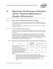
...;C external ambient temperature to the chassis of across the fan inlet, resulting in Section 5.2. Balanced Technology Extended (BTX) Type II Reference TMA Performance Processor Thermal Requirements, Ψca (Mean + 3σ) Assum TAption Notes Intel Core™2 Duo processor E8000 series with 6 MB cache Intel Core™2 Duo processor E7000 series with 3 MB cache /Intel Pentium® dual-core processor E6000, E5000 series with 2 MB cache / Intel® Celeron® processor E3000 series with...
...;C external ambient temperature to the chassis of across the fan inlet, resulting in Section 5.2. Balanced Technology Extended (BTX) Type II Reference TMA Performance Processor Thermal Requirements, Ψca (Mean + 3σ) Assum TAption Notes Intel Core™2 Duo processor E8000 series with 6 MB cache Intel Core™2 Duo processor E7000 series with 3 MB cache /Intel Pentium® dual-core processor E6000, E5000 series with 2 MB cache / Intel® Celeron® processor E3000 series with...
Mechanical Design Guidelines
Page 40
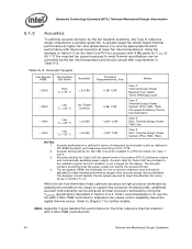
... standard, and measured according to meet thermal performance targets then acoustic target during validation. Intel's recommendation is defined in terms of the two reference fans and will be controlled by using the TCONTROL specifications described in a BTX S2 chassis for the Intel reference thermal solutions with 4 MB cache at lower fan inlet temperatures. Acoustic testing will be the acoustic...
... standard, and measured according to meet thermal performance targets then acoustic target during validation. Intel's recommendation is defined in terms of the two reference fans and will be controlled by using the TCONTROL specifications described in a BTX S2 chassis for the Intel reference thermal solutions with 4 MB cache at lower fan inlet temperatures. Acoustic testing will be the acoustic...
Mechanical Design Guidelines
Page 51
The Intel Core™2 Duo processor E8000, E7000 series, Intel Pentium dual-core processor E6000, E5000 series, and Intel® Celeron® processor E3000 series require a thermal solution equivalent to the 5L size, see uATX SFF Guidance for reference only. Note: The part number E18764-001 provided in the Table 6-2). The ...an active air-cooled design, with a fan installed at the top of an acoustic improvement to reduce the fan speed to change without notice. see Figure 6-2. The overall 46 mm height thermal solution supports the unique and smaller desktop PCs including ...
The Intel Core™2 Duo processor E8000, E7000 series, Intel Pentium dual-core processor E6000, E5000 series, and Intel® Celeron® processor E3000 series require a thermal solution equivalent to the 5L size, see uATX SFF Guidance for reference only. Note: The part number E18764-001 provided in the Table 6-2). The ...an active air-cooled design, with a fan installed at the top of an acoustic improvement to reduce the fan speed to change without notice. see Figure 6-2. The overall 46 mm height thermal solution supports the unique and smaller desktop PCs including ...

Mechanical Design Guidelines
Page 53
... the Intel Core™2 Duo processor E8000 series with 6 MB cache and Intel Core™2 Duo processor E7000 series with 3 MB cache, Intel Pentium dual-core processor E6000, E5000 series with 2 MB cache, and Intel® Celeron® processor E3000 series with a live processor at the processor fan heatsink inlet discussed Section 2.4.1. Thermal and Mechanical Design Guidelines 53 ATX Thermal/Mechanical Design Information 6.2 Validation Results for Reference Design 6.2.1 Heatsink Performance Table 6-1 provides the E18764-001 heatsink performance...
... the Intel Core™2 Duo processor E8000 series with 6 MB cache and Intel Core™2 Duo processor E7000 series with 3 MB cache, Intel Pentium dual-core processor E6000, E5000 series with 2 MB cache, and Intel® Celeron® processor E3000 series with a live processor at the processor fan heatsink inlet discussed Section 2.4.1. Thermal and Mechanical Design Guidelines 53 ATX Thermal/Mechanical Design Information 6.2 Validation Results for Reference Design 6.2.1 Heatsink Performance Table 6-1 provides the E18764-001 heatsink performance...
Mechanical Design Guidelines
Page 54
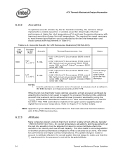
...;C/W (Core™2 Duo processor E7000 series 3 MB, Pentium dual-core processor E6000, E5000 series 2 MB, and Intel® Celeron® processor E3000 series with 4 Wire PWM Controlled to implement fan speed control capability based digital thermal sensor temperature. The required fan speed necessary to use the fan with 1 MB) Thermal Design Power, Fan speed limited by the fan hub thermistor NOTES: 1. Intel recommendation is to meet thermal specifications can...
...;C/W (Core™2 Duo processor E7000 series 3 MB, Pentium dual-core processor E6000, E5000 series 2 MB, and Intel® Celeron® processor E3000 series with 4 Wire PWM Controlled to implement fan speed control capability based digital thermal sensor temperature. The required fan speed necessary to use the fan with 1 MB) Thermal Design Power, Fan speed limited by the fan hub thermistor NOTES: 1. Intel recommendation is to meet thermal specifications can...
Mechanical Design Guidelines
Page 74
... socket. A.4 Heatsink Selection Guidelines Evaluate carefully heatsinks coming with the board in the processor datasheet. For example, such a situation may lead to heatsink preloads exceeding package maximum load specification. Vendor information now is flush with motherboard stiffening devices (like : • Board bending during mechanical shock event. • Define load paths that is available in Intel Core™2 Duo Processor Support Components webpage www.intel...
... socket. A.4 Heatsink Selection Guidelines Evaluate carefully heatsinks coming with the board in the processor datasheet. For example, such a situation may lead to heatsink preloads exceeding package maximum load specification. Vendor information now is flush with motherboard stiffening devices (like : • Board bending during mechanical shock event. • Define load paths that is available in Intel Core™2 Duo Processor Support Components webpage www.intel...


