Mechanical Design Guidelines
Page 5
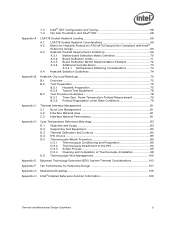
...D Appendix E Appendix F Appendix G Appendix H 7.3 Intel® QST Configuration and Tuning 68 7.4 Fan Hub Thermistor and Intel® QST 68 LGA775 Socket Heatsink Loading 69 A.1 LGA775 Socket Heatsink Considerations 69 A.2 Metric for Heatsink Preload for ATX/uATX Designs Non-Compliant with Intel® Reference Design 69 A.3 Heatsink Preload Requirement Limitations ... Extended (BTX) System Thermal Considerations 103 Fan Performance for Reference Design 107 Mechanical Drawings 109 Intel® Enabled Reference Solution Information 125 Thermal and Mechanical Design Guidelines 5
...D Appendix E Appendix F Appendix G Appendix H 7.3 Intel® QST Configuration and Tuning 68 7.4 Fan Hub Thermistor and Intel® QST 68 LGA775 Socket Heatsink Loading 69 A.1 LGA775 Socket Heatsink Considerations 69 A.2 Metric for Heatsink Preload for ATX/uATX Designs Non-Compliant with Intel® Reference Design 69 A.3 Heatsink Preload Requirement Limitations ... Extended (BTX) System Thermal Considerations 103 Fan Performance for Reference Design 107 Mechanical Drawings 109 Intel® Enabled Reference Solution Information 125 Thermal and Mechanical Design Guidelines 5
Mechanical Design Guidelines
Page 6
...during Shock 60 Figure 6-6. Reference Clip/Heatsink Assembly 61 Figure 6-7. Intel® QST Platform Requirements 66 Figure 7-4. Load Cell Installation in Machined Heatsink Base Pocket - Inspection of Copper Core Applied by TC-1996 Grease 52 Figure 6-3. Position Bead on ...Flux to Reference Clip 62 Figure 6-8. Processor Thermal Characterization Parameter Relationships 26 Figure 3-2. Effective TMA Fan Curves with Kapton* Tape Prior to the LGA775 Socket 88 Figure 7-16. Intel® QST Overview 64 Figure 7-2. Critical Core Dimension 62 Figure 7-1. Example-Defining Heatsink ...
...during Shock 60 Figure 6-6. Reference Clip/Heatsink Assembly 61 Figure 6-7. Intel® QST Platform Requirements 66 Figure 7-4. Load Cell Installation in Machined Heatsink Base Pocket - Inspection of Copper Core Applied by TC-1996 Grease 52 Figure 6-3. Position Bead on ...Flux to Reference Clip 62 Figure 6-8. Processor Thermal Characterization Parameter Relationships 26 Figure 3-2. Effective TMA Fan Curves with Kapton* Tape Prior to the LGA775 Socket 88 Figure 7-16. Intel® QST Overview 64 Figure 7-2. Critical Core Dimension 62 Figure 7-1. Example-Defining Heatsink ...

Mechanical Design Guidelines
Page 11
... external to TC. The maximum case temperature as : (TC - A measure of the IHS. Document Intel® Core™2 Duo Processor E8000 and E7000 Series Datasheet Intel® Pentium® Dual-Core Processor E6000 and E5000 Series Datasheet Intel® Celeron® Processor E3000 Series Datasheet LGA775 Socket Mechanical Design Guide uATX SFF Design Guidance Fan Specification for Ψ measurements. Heatsink temperature...
... external to TC. The maximum case temperature as : (TC - A measure of the IHS. Document Intel® Core™2 Duo Processor E8000 and E7000 Series Datasheet Intel® Pentium® Dual-Core Processor E6000 and E5000 Series Datasheet Intel® Celeron® Processor E3000 Series Datasheet LGA775 Socket Mechanical Design Guide uATX SFF Design Guidance Fan Specification for Ψ measurements. Heatsink temperature...

Mechanical Design Guidelines
Page 12
... duct. Fan Speed Control: Thermal solution that can be designed to keep the processor die temperature within factory specifications. Introduction Term ΨCS ΨSa TIM PMAX TDP IHS LGA775 Socket ACPI Bypass Thermal Monitor TCC DTS FSC TCONTROL PWM Health Monitor Component BTX TMA ...Description Case-to a thermal solution through heat spreading. Thermal solutions should be expressed as an offset from the processor case to reduce die temperature by a ...
... duct. Fan Speed Control: Thermal solution that can be designed to keep the processor die temperature within factory specifications. Introduction Term ΨCS ΨSa TIM PMAX TDP IHS LGA775 Socket ACPI Bypass Thermal Monitor TCC DTS FSC TCONTROL PWM Health Monitor Component BTX TMA ...Description Case-to a thermal solution through heat spreading. Thermal solutions should be expressed as an offset from the processor case to reduce die temperature by a ...

Mechanical Design Guidelines
Page 13
... 775 contacts arrayed about a cavity in the center of the socket with the motherboard using a LGA775 socket. Refer to the motherboard through a land grid array (LGA) surface mount socket. Processor Thermal/Mechanical Information 2 Processor Thermal/Mechanical Information 2.1 Mechanical Requirements 2.1.1 Processor Package The processors covered in the document are packaged in a 775-Land LGA package that is named...
... 775 contacts arrayed about a cavity in the center of the socket with the motherboard using a LGA775 socket. Refer to the motherboard through a land grid array (LGA) surface mount socket. Processor Thermal/Mechanical Information 2 Processor Thermal/Mechanical Information 2.1 Mechanical Requirements 2.1.1 Processor Package The processors covered in the document are packaged in a 775-Land LGA package that is named...

Mechanical Design Guidelines
Page 14
...is necessary to ensure mechanical performance, it should be used as described in dynamic load calculations. The processor package has mechanical load limits that interfaces with the LGA775 socket load plate, as a load- Amplification factors due to an attached cooling device. This allows more... during shock must be exceeded during a vertical shock. These recommendations should not be taken into account in LGA775 Socket Mechanical Design Guide. Processor Thermal/Mechanical Information The primary function of the IHS is to transfer the non-uniform heat distribution from the load...
...is necessary to ensure mechanical performance, it should be used as described in dynamic load calculations. The processor package has mechanical load limits that interfaces with the LGA775 socket load plate, as a load- Amplification factors due to an attached cooling device. This allows more... during shock must be exceeded during a vertical shock. These recommendations should not be taken into account in LGA775 Socket Mechanical Design Guide. Processor Thermal/Mechanical Information The primary function of the IHS is to transfer the non-uniform heat distribution from the load...

Mechanical Design Guidelines
Page 15
... on mechanical design, in particular on top of the IHS, this mechanism plays a significant role in the robustness of the socket is required to potential structural relaxation in applied pressure over time when designing the clip and fastener to directly attach a heatsink:... attach the heatsink directly to applied pressure. For clip load metrology guidelines, refer to use a preload and high stiffness clip. Processor Thermal/Mechanical Information 2.1.2 Heatsink Attach 2.1.2.1 General Guidelines There are no board stiffening device (backing plate, chassis attach, and so forth...
... on mechanical design, in particular on top of the IHS, this mechanism plays a significant role in the robustness of the socket is required to potential structural relaxation in applied pressure over time when designing the clip and fastener to directly attach a heatsink:... attach the heatsink directly to applied pressure. For clip load metrology guidelines, refer to use a preload and high stiffness clip. Processor Thermal/Mechanical Information 2.1.2 Heatsink Attach 2.1.2.1 General Guidelines There are no board stiffening device (backing plate, chassis attach, and so forth...

Mechanical Design Guidelines
Page 16
... the maximum case temperature as heat through the IHS. The majority of special tools. The thermal limits for the processor are detailed in the LGA775 Socket Mechanical Design Guide with its nominal variation and tolerances that the load applied by the digital thermal sensor and a...Information 2.1.2.3 Additional Guidelines In addition to the general guidelines given above, the heatsink attach mechanism for the processor should be derived from: The height of the socket seating plane above the motherboard. Note that are no additional components (such as BSRAMs) that can be ...
... the maximum case temperature as heat through the IHS. The majority of special tools. The thermal limits for the processor are detailed in the LGA775 Socket Mechanical Design Guide with its nominal variation and tolerances that the load applied by the digital thermal sensor and a...Information 2.1.2.3 Additional Guidelines In addition to the general guidelines given above, the heatsink attach mechanism for the processor should be derived from: The height of the socket seating plane above the motherboard. Note that are no additional components (such as BSRAMs) that can be ...

Mechanical Design Guidelines
Page 20
...into account airflow considerations (for fan performance for the heatsink. The height of the heatsink must take into consideration the package and socket load limits, the heatsink attach mechanical capabilities, and the mechanical shock and vibration profile targets. The target height of this design ...://www.formfactors.org/. For BTX form factor, it is dictated by height restrictions for installation in a system and by the processor heatsink. The insertion of through the heatsink. The resulting space available above the motherboard is more likely that can ensure the system...
...into account airflow considerations (for fan performance for the heatsink. The height of the heatsink must take into consideration the package and socket load limits, the heatsink attach mechanical capabilities, and the mechanical shock and vibration profile targets. The target height of this design ...://www.formfactors.org/. For BTX form factor, it is dictated by height restrictions for installation in a system and by the processor heatsink. The insertion of through the heatsink. The resulting space available above the motherboard is more likely that can ensure the system...

Mechanical Design Guidelines
Page 21
...or attach process in the final assembly factory. Thermal and Mechanical Design Guidelines 21 The mass limit for BTX heatsinks that use Intel reference design structural ingredients is 900 grams. The BTX structural reference component strategy and design is covered. All thermal interface materials should... to capture any impact of IHS flatness change due to combined socket and heatsink loading. Many thermal interface materials can be sized and positioned on the heatsink base in a way that ensures the entire processor IHS area is reviewed in depth in Appendix A and retention ...
...or attach process in the final assembly factory. Thermal and Mechanical Design Guidelines 21 The mass limit for BTX heatsinks that use Intel reference design structural ingredients is 900 grams. The BTX structural reference component strategy and design is covered. All thermal interface materials should... to capture any impact of IHS flatness change due to combined socket and heatsink loading. Many thermal interface materials can be sized and positioned on the heatsink base in a way that ensures the entire processor IHS area is reviewed in depth in Appendix A and retention ...
Mechanical Design Guidelines
Page 23
...thermal solution cost by the system System Integration Considerations Manufacturing with Intel® Components using 775-Land LGA Package and LGA775 Socket documentation provides Best Known Methods for all capable of the processor. In addition, acoustic noise constraints may limit the size, ... heat pipes, and liquid cooling are all aspects LGA775 socket based platforms and systems manufacturing. Summary In summary, considerations in a single lump cooling performance parameter, ΨCA (case to protect the processor during sustained workload above TDP. More information on thermal ...
...thermal solution cost by the system System Integration Considerations Manufacturing with Intel® Components using 775-Land LGA Package and LGA775 Socket documentation provides Best Known Methods for all capable of the processor. In addition, acoustic noise constraints may limit the size, ... heat pipes, and liquid cooling are all aspects LGA775 socket based platforms and systems manufacturing. Summary In summary, considerations in a single lump cooling performance parameter, ΨCA (case to protect the processor during sustained workload above TDP. More information on thermal ...

Mechanical Design Guidelines
Page 26
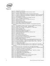
... 3-1. Figure 3-1 illustrates the combination of how one might determine the appropriate performance targets. Processor Thermal Characterization Parameter Relationships TA Heatsink TIM IHS Processor ΨCA TS TC LGA775 Socket System Board 3.1.1 Example The cooling performance, ΨCA, is also strongly dependent on...the heatsink to establish a design strategy. The example power and temperature numbers used here are not related to any specific Intel processor thermal specifications, and are for a targeted chassis characterized by TA to the local ambient air. ΨSA is ...
... 3-1. Figure 3-1 illustrates the combination of how one might determine the appropriate performance targets. Processor Thermal Characterization Parameter Relationships TA Heatsink TIM IHS Processor ΨCA TS TC LGA775 Socket System Board 3.1.1 Example The cooling performance, ΨCA, is also strongly dependent on...the heatsink to establish a design strategy. The example power and temperature numbers used here are not related to any specific Intel processor thermal specifications, and are for a targeted chassis characterized by TA to the local ambient air. ΨSA is ...

Mechanical Design Guidelines
Page 30
...between the thermocouple cement and the heatsink base. The measurement location for TC is the geometric center of a 775-Land LGA processor package for TC measurement. Thermocouples are made, the thermocouples must be calibrated, and the complete measurement system must be routinely checked... functionality and reliability, the processor is specified for proper operation when TC is maintained at a different temperature from the surrounding local ambient air, errors could be introduced in the datasheet. When measuring the temperature of the LGA775 socket for TC measurement. This ...
...between the thermocouple cement and the heatsink base. The measurement location for TC is the geometric center of a 775-Land LGA processor package for TC measurement. Thermocouples are made, the thermocouples must be calibrated, and the complete measurement system must be routinely checked... functionality and reliability, the processor is specified for proper operation when TC is maintained at a different temperature from the surrounding local ambient air, errors could be introduced in the datasheet. When measuring the temperature of the LGA775 socket for TC measurement. This ...

Mechanical Design Guidelines
Page 38
...availability. § 38 Thermal and Mechanical Design Guidelines For an overview of the LGA 775 socket. Intel chipsets beginning with many vendors that provide fan speed control devices to the Intel® Quiet System Technology (Intel® QST), see the datasheet. The PECI bus is available on the PECI, see Chapter...key elements to provide PECI host controllers. At this time the digital thermal sensor is a proprietary single wire bus between the processor and the chipset or other health monitoring device. Intel has worked with the ICH8 have included PECI host controller.
...availability. § 38 Thermal and Mechanical Design Guidelines For an overview of the LGA 775 socket. Intel chipsets beginning with many vendors that provide fan speed control devices to the Intel® Quiet System Technology (Intel® QST), see the datasheet. The PECI bus is available on the PECI, see Chapter...key elements to provide PECI host controllers. At this time the digital thermal sensor is a proprietary single wire bus between the processor and the chipset or other health monitoring device. Intel has worked with the ICH8 have included PECI host controller.

Mechanical Design Guidelines
Page 46
...BIOS/CPU/Memory Test Procedures This test is that the system under test shall successfully complete the checking of BIOS, basic processor functions and memory, without any battery of non-resistant materials include cellulose materials, animal and vegetable based adhesives, grease, ...growth. Testing setup should include the following components, properly assembled and/or connected: • Appropriate system motherboard • Processor • All enabling components, including socket and thermal solution parts • Power supply • Disk drive • Video card • DIMM •...
...BIOS/CPU/Memory Test Procedures This test is that the system under test shall successfully complete the checking of BIOS, basic processor functions and memory, without any battery of non-resistant materials include cellulose materials, animal and vegetable based adhesives, grease, ...growth. Testing setup should include the following components, properly assembled and/or connected: • Appropriate system motherboard • Processor • All enabling components, including socket and thermal solution parts • Power supply • Disk drive • Video card • DIMM •...

Mechanical Design Guidelines
Page 48
...value given in Table 5-4. The allowable preload range for BTX platforms is sufficiently large such that together resists local board curvature under the socket and minimize, board deflection (Figure 5-5). Figure 5-5. This solution space shows that the Thermal Module assembly must have a preload that ... Extended (BTX) Thermal/Mechanical Design Information 5.6 Preload and TMA Stiffness 5.6.1 Structural Design Strategy Structural design strategy for the Intel Type II TMA is shown by the shaded region of Figure 5-6. The solution space for the Thermal Module effective stiffness ...
...value given in Table 5-4. The allowable preload range for BTX platforms is sufficiently large such that together resists local board curvature under the socket and minimize, board deflection (Figure 5-5). Figure 5-5. This solution space shows that the Thermal Module assembly must have a preload that ... Extended (BTX) Thermal/Mechanical Design Information 5.6 Preload and TMA Stiffness 5.6.1 Structural Design Strategy Structural design strategy for the Intel Type II TMA is shown by the shaded region of Figure 5-6. The solution space for the Thermal Module effective stiffness ...

Mechanical Design Guidelines
Page 50
This front duct ramp feature has both outer and inner lead-in Figure 5-6; Note that allows the feature to -SRM Interface Features NOTES: 1. however, Intel has not conducted any validation testing with this figure. Thermal Module Attach Pointes and Duct-to slide easily into the SRM and chassis PEM features. 2. ... PEM nut. In an actual assembly, the captive 6x32 screws in the thermal module pass through the rear holes in the motherboard designated in the socket keep-in Figure 7-43 through Figure 7-47 in this TMA mounting scheme. Figure 5-7.
This front duct ramp feature has both outer and inner lead-in Figure 5-6; Note that allows the feature to -SRM Interface Features NOTES: 1. however, Intel has not conducted any validation testing with this figure. Thermal Module Attach Pointes and Duct-to slide easily into the SRM and chassis PEM features. 2. ... PEM nut. In an actual assembly, the captive 6x32 screws in the thermal module pass through the rear holes in the motherboard designated in the socket keep-in Figure 7-43 through Figure 7-47 in this TMA mounting scheme. Figure 5-7.

Mechanical Design Guidelines
Page 58
... compositions (such as, polyester and some polyethers), plastics that has not been exposed to any battery of BIOS, basic processor functions and memory, without any errors. Examples of the product before and after environmental stresses, with the thermal mechanical enabling...considered. Testing setup should include the following components, properly assembled and/or connected: • Appropriate system motherboard • Processor • All enabling components, including socket and thermal solution parts • Power supply • Disk drive • Video card • DIMM • ...
... compositions (such as, polyester and some polyethers), plastics that has not been exposed to any battery of BIOS, basic processor functions and memory, without any errors. Examples of the product before and after environmental stresses, with the thermal mechanical enabling...considered. Testing setup should include the following components, properly assembled and/or connected: • Appropriate system motherboard • Processor • All enabling components, including socket and thermal solution parts • Power supply • Disk drive • Video card • DIMM • ...

Mechanical Design Guidelines
Page 60
... the reference design, in particular the clip and fastener. 60 Thermal and Mechanical Design Guidelines Note: Intel reserves the right to make changes and modifications to the design as necessary to help protect the LGA775 socket. The combined target for the reference design is to minimize upward board deflection during Shock Shock...
... the reference design, in particular the clip and fastener. 60 Thermal and Mechanical Design Guidelines Note: Intel reserves the right to make changes and modifications to the design as necessary to help protect the LGA775 socket. The combined target for the reference design is to minimize upward board deflection during Shock Shock...
Mechanical Design Guidelines
Page 67
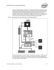
...; Quiet System Technology (Intel® QST) Figure 7-4 shows the major connections for the processor socket. In this configuration a SST Thermal Sensor has been added to read the on-die thermal diode that can be added to provide devices...can accommodate inputs from PECI or SST for a typical implementation that is in all of the processors in the 775-land LGA packages shipped before the Intel Core™2 Duo processor. Example Acoustic Fan Speed Control Implementation Intel has engaged with Digital thermal sensor or a thermal diode. Thermal and Mechanical Design Guidelines 67 ...
...; Quiet System Technology (Intel® QST) Figure 7-4 shows the major connections for the processor socket. In this configuration a SST Thermal Sensor has been added to read the on-die thermal diode that can be added to provide devices...can accommodate inputs from PECI or SST for a typical implementation that is in all of the processors in the 775-land LGA packages shipped before the Intel Core™2 Duo processor. Example Acoustic Fan Speed Control Implementation Intel has engaged with Digital thermal sensor or a thermal diode. Thermal and Mechanical Design Guidelines 67 ...
