Data Sheet
Page 2
... and shall have no responsibility whatsoever for Intel 64. The Intel Pentium® dual-core processor E5000 and E6000 series may contain design defects or errors known as the property of Intel Corporation in any features or instructions marked "reserved" or "undefined." Intel processor numbers are trademarks of others. See www.intel.com/products/processor_number for details. Enabling Execute...
... and shall have no responsibility whatsoever for Intel 64. The Intel Pentium® dual-core processor E5000 and E6000 series may contain design defects or errors known as the property of Intel Corporation in any features or instructions marked "reserved" or "undefined." Intel processor numbers are trademarks of others. See www.intel.com/products/processor_number for details. Enabling Execute...
Data Sheet
Page 3
... 2.6.4 Die Voltage Validation 21 2.7 Signaling Specifications 21 2.7.1 FSB Signal Groups 22 2.7.2 CMOS and Open Drain Signals 23 2.7.3 Processor DC Specifications 24 2.7.3.1 Platform Environment Control Interface (PECI) DC Specifications..... 25 2.7.3.2 GTL+ Front Side Bus Specifications 26 2.8 ...Clock Specifications 27 2.8.1 Front Side Bus Clock (BCLK[1:0]) and Processor Clocking 27 2.8.2 FSB Frequency Select Signals (BSEL[2:0 28 2.8.3 Phase Lock Loop (PLL) and Filter 29 2.8.4 BCLK[1:0] Specifications 29 ...
... 2.6.4 Die Voltage Validation 21 2.7 Signaling Specifications 21 2.7.1 FSB Signal Groups 22 2.7.2 CMOS and Open Drain Signals 23 2.7.3 Processor DC Specifications 24 2.7.3.1 Platform Environment Control Interface (PECI) DC Specifications..... 25 2.7.3.2 GTL+ Front Side Bus Specifications 26 2.8 ...Clock Specifications 27 2.8.1 Front Side Bus Clock (BCLK[1:0]) and Processor Clocking 27 2.8.2 FSB Frequency Select Signals (BSEL[2:0 28 2.8.3 Phase Lock Loop (PLL) and Filter 29 2.8.4 BCLK[1:0] Specifications 29 ...
Data Sheet
Page 4
... 88 6.2.6 Deep Sleep State 89 6.2.7 Deeper Sleep State 89 6.2.8 Enhanced Intel® SpeedStep® Technology 90 6.3 Processor Power Status Indicator (PSI) Signal 90 7 Boxed Processor Specifications 91 7.1 Introduction ...91 7.2 Mechanical Specifications 92 7.2.1 Boxed Processor Cooling Solution Dimensions 92 7.2.2 Boxed Processor Fan Heatsink Weight 93 7.2.3 Boxed Processor Retention Mechanism and Heatsink Attach Clip Assembly .....93 7.3 Electrical Requirements...
... 88 6.2.6 Deep Sleep State 89 6.2.7 Deeper Sleep State 89 6.2.8 Enhanced Intel® SpeedStep® Technology 90 6.3 Processor Power Status Indicator (PSI) Signal 90 7 Boxed Processor Specifications 91 7.1 Introduction ...91 7.2 Mechanical Specifications 92 7.2.1 Boxed Processor Cooling Solution Dimensions 92 7.2.2 Boxed Processor Fan Heatsink Weight 93 7.2.3 Boxed Processor Retention Mechanism and Heatsink Attach Clip Assembly .....93 7.3 Electrical Requirements...
Data Sheet
Page 5
... Fan Control Diagram on PECI-Based Platforms 82 18 Processor Low Power State Machine 86 19 Mechanical Representation of 3 36 9 Intel® Pentium® Dual-Core Processor E5000 Series Top-Side Markings Example 38 10 Intel® Pentium® Dual-Core Processor E6000 Series Top-Side Markings Example 39 11 Processor Land Coordinates and Quadrants, Top View 40 12 land...
... Fan Control Diagram on PECI-Based Platforms 82 18 Processor Low Power State Machine 86 19 Mechanical Representation of 3 36 9 Intel® Pentium® Dual-Core Processor E5000 Series Top-Side Markings Example 38 10 Intel® Pentium® Dual-Core Processor E6000 Series Top-Side Markings Example 39 11 Processor Land Coordinates and Quadrants, Top View 40 12 land...
Data Sheet
Page 6
...Specifications 24 12 CMOS Signal Group DC Specifications 25 13 PECI DC Electrical Limits 26 14 GTL+ Bus Voltage Definitions 27 15 Core Frequency to FSB Multiplier Configuration 28 16 BSEL[2:0] Frequency Table for BCLK[1:0 29 17 Front Side Bus Differential BCLK Specifications 29 18... Differential Clock Specifications (800 MHz FSB 30 19 FSB Differential Clock Specifications (1066 MHz FSB 30 20 Processor Loading Specifications 37 21 Package Handling Guidelines 37 22 Processor Materials 38 23 Alphabetical Land Assignments 44 24 Numerical Land Assignment 54 25 Signal Description...64 26...
...Specifications 24 12 CMOS Signal Group DC Specifications 25 13 PECI DC Electrical Limits 26 14 GTL+ Bus Voltage Definitions 27 15 Core Frequency to FSB Multiplier Configuration 28 16 BSEL[2:0] Frequency Table for BCLK[1:0 29 17 Front Side Bus Differential BCLK Specifications 29 18... Differential Clock Specifications (800 MHz FSB 30 19 FSB Differential Clock Specifications (1066 MHz FSB 30 20 Processor Loading Specifications 37 21 Package Handling Guidelines 37 22 Processor Materials 38 23 Alphabetical Land Assignments 44 24 Numerical Land Assignment 54 25 Signal Description...64 26...
Data Sheet
Page 7
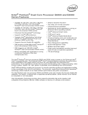
... at 3.33 GHz, 3.20 GHz, 3.06 GHz, 2.93 GHz, and 2.80 GHz (Intel® Pentium® Dual-Core processor E6000 series) • Enhanced Intel Speedstep® Technology • Supports Intel® 64 architecture • Supports Intel® Virtualization Technology (Intel® VT) (Intel® Pentium® Dual-Core processor E6000 series only) • Supports Execute Disable Bit capability • FSB frequency at...
... at 3.33 GHz, 3.20 GHz, 3.06 GHz, 2.93 GHz, and 2.80 GHz (Intel® Pentium® Dual-Core processor E6000 series) • Enhanced Intel Speedstep® Technology • Supports Intel® 64 architecture • Supports Intel® Virtualization Technology (Intel® VT) (Intel® Pentium® Dual-Core processor E6000 series only) • Supports Execute Disable Bit capability • FSB frequency at...
Data Sheet
Page 9
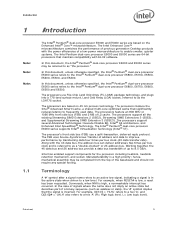
... this document, unless otherwise specified, the Intel® Pentium® dual-core processor E5000 series refers to the Intel® Pentium® dual-core processor E6800, E6700, E6600, E6500 and E6300. In this document, the Intel® Pentium® dual-core processor E6000 and E5000 series may be referred to as "the processor." The processors are 64-bit processors that significantly reduces latency to a low level...
... this document, unless otherwise specified, the Intel® Pentium® dual-core processor E5000 series refers to the Intel® Pentium® dual-core processor E6800, E6700, E6600, E6500 and E6300. In this document, the Intel® Pentium® dual-core processor E6000 and E5000 series may be referred to as "the processor." The processors are 64-bit processors that significantly reduces latency to a low level...
Data Sheet
Page 10
... Commonly used terms are satisfied. • Execute Disable Bit - Voltage Regulator-Down (VRD) 11.0 Processor Power Delivery Design Guidelines For Desktop LGA775 Socket • Enhanced Intel® Core™ microarchitecture - Processor die with a 2 MB L2 cache. • Intel® Pentium® dual-core processor E6000 series - All memory and I/O transactions, as well as interrupt messages, pass between the...
... Commonly used terms are satisfied. • Execute Disable Bit - Voltage Regulator-Down (VRD) 11.0 Processor Power Delivery Design Guidelines For Desktop LGA775 Socket • Enhanced Intel® Core™ microarchitecture - Processor die with a 2 MB L2 cache. • Intel® Pentium® dual-core processor E6000 series - All memory and I/O transactions, as well as interrupt messages, pass between the...
Data Sheet
Page 11
... and enables more detailed information. • Intel® 64 Architecture- Enhanced Intel SpeedStep Technology allows trade-offs to take advantage of the system. References Document Location Intel® Pentium® Dual-Core Processor E6000 and E5000 Series Specification Update Intel® Core™2 Duo processor E8000 and E7000 Series, and Intel® Pentium® Dual-Core Processor E6000 and E5000 Series Thermal and Mechanical...
... and enables more detailed information. • Intel® 64 Architecture- Enhanced Intel SpeedStep Technology allows trade-offs to take advantage of the system. References Document Location Intel® Pentium® Dual-Core Processor E6000 and E5000 Series Specification Update Intel® Core™2 Duo processor E8000 and E7000 Series, and Intel® Pentium® Dual-Core Processor E6000 and E5000 Series Thermal and Mechanical...
Data Sheet
Page 13
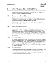
...VCC Decoupling VCC regulator solutions need to provide sufficient decoupling capacitance to its large number of the component. Contact your Intel field representative for these lands, that the voltage provided to a system ground plane. This includes bulk capacitance with... the power delivery solution must be supplied the voltage determined by the front side bus and processor activity. Electrical Specifications 2 Electrical Specifications 2.1 2.2 2.2.1 2.2.2 This chapter describes the electrical characteristics of low ESR bulk capacitors and...
...VCC Decoupling VCC regulator solutions need to provide sufficient decoupling capacitance to its large number of the component. Contact your Intel field representative for these lands, that the voltage provided to a system ground plane. This includes bulk capacitance with... the power delivery solution must be supplied the voltage determined by the front side bus and processor activity. Electrical Specifications 2 Electrical Specifications 2.1 2.2 2.2.1 2.2.2 This chapter describes the electrical characteristics of low ESR bulk capacitors and...
Data Sheet
Page 14
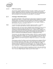
...requires additional platform support. See the Intel® Pentium® dualcore Processor E6000 and E5000 Series Specification Update for further details on specific valid core frequency and VID values of the high frequency capacitance required for each processor frequency is the reference VR output ...voltage to be noted that two devices at the same core speed may be calibrated during a power management event (Thermal Monitor 2, Enhanced Intel SpeedStep® technology, or Extended HALT ...
...requires additional platform support. See the Intel® Pentium® dualcore Processor E6000 and E5000 Series Specification Update for further details on specific valid core frequency and VID values of the high frequency capacitance required for each processor frequency is the reference VR output ...voltage to be noted that two devices at the same core speed may be calibrated during a power management event (Thermal Monitor 2, Enhanced Intel SpeedStep® technology, or Extended HALT ...
Data Sheet
Page 16
...much power and cause a potential VR issue. 16 Datasheet For optimum noise margin, all RESERVED lands. For example, a 130 W TDP processor installed in a board with other TESTHI signals • TESTHI12/FC44 - Electrical Specifications 2.4 2.5 Reserved, Unused, and TESTHI Signals All RESERVED..., and prevent boundary scan testing. Power Segment Identifier (PSID) Power Segment Identifier (PSID) is a mechanism to detect if the processor in component malfunction or incompatibility with a single pull-up resistors or be grouped with other TESTHI signals • TESTHI10 - cannot ...
...much power and cause a potential VR issue. 16 Datasheet For optimum noise margin, all RESERVED lands. For example, a 130 W TDP processor installed in a board with other TESTHI signals • TESTHI12/FC44 - Electrical Specifications 2.4 2.5 Reserved, Unused, and TESTHI Signals All RESERVED..., and prevent boundary scan testing. Power Segment Identifier (PSID) Power Segment Identifier (PSID) is a mechanism to detect if the processor in component malfunction or incompatibility with a single pull-up resistors or be grouped with other TESTHI signals • TESTHI10 - cannot ...
Data Sheet
Page 17
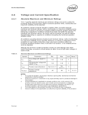
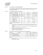
...depending on any signal will not affect the long-term reliability of the device. Excessive overshoot or undershoot on exposure to the processor. 3. At conditions exceeding absolute maximum and minimum ratings, neither functionality nor long-term reliability can be expected. V - &#...Maximum and Minimum Ratings Symbol Parameter Min VCC Core voltage with respect to VSS -0.3 VTT FSB termination voltage with its reliability will be connected to VSS -0.3 TCASE Processor case temperature See Section 5 TSTORAGE Processor storage temperature -40 Max 1.45 1.45 See...
...depending on any signal will not affect the long-term reliability of the device. Excessive overshoot or undershoot on exposure to the processor. 3. At conditions exceeding absolute maximum and minimum ratings, neither functionality nor long-term reliability can be expected. V - &#...Maximum and Minimum Ratings Symbol Parameter Min VCC Core voltage with respect to VSS -0.3 VTT FSB termination voltage with its reliability will be connected to VSS -0.3 TCASE Processor case temperature See Section 5 TSTORAGE Processor storage temperature -40 Max 1.45 1.45 See...
Data Sheet
Page 18
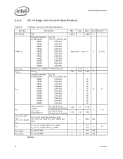
... Parameter Min Typ Max Unit Notes2, 10 VID Range VID 0.8500 - 1.3625 V Core VCC Processor Number (2 MB Cache): VCC for 775_VR_CONFIG_06: E6800 3.33 GHz E6700 3.20 GHz E6600 3.06 GHz E6500 2.93 GHz E6300 2.80 GHz See Table 5, Figure 1 V E5200 2.50 GHz E5300 2.66 GHz ... E5500 2.80 GHz 75 E5700 3.00 GHz 75 E5800 3.20 GHz 75 FSB termination voltage on Intel 3 series Chipset family boards 1.045 1.1 1.155 VTT (DC + AC specifications) on Intel 4 series Chipset family boards 1.14 V 1.2 1.26 VTT_OUT_LEFT and VTT_OUT_RIGHT ICC ITT ICC_VCCPLL ICC_GTLREF DC...
... Parameter Min Typ Max Unit Notes2, 10 VID Range VID 0.8500 - 1.3625 V Core VCC Processor Number (2 MB Cache): VCC for 775_VR_CONFIG_06: E6800 3.33 GHz E6700 3.20 GHz E6600 3.06 GHz E6500 2.93 GHz E6300 2.80 GHz See Table 5, Figure 1 V E5200 2.50 GHz E5300 2.66 GHz ... E5500 2.80 GHz 75 E5700 3.00 GHz 75 E5800 3.20 GHz 75 FSB termination voltage on Intel 3 series Chipset family boards 1.045 1.1 1.155 VTT (DC + AC specifications) on Intel 4 series Chipset family boards 1.14 V 1.2 1.26 VTT_OUT_LEFT and VTT_OUT_RIGHT ICC ITT ICC_VCCPLL ICC_GTLREF DC...
Data Sheet
Page 19
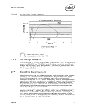
Each processor is programmed with a maximum valid voltage identification value (VID), which is measured at the land. 8. These voltages are calibrated during a power management event (Thermal Monitor 2, Enhanced Intel SpeedStep technology, or Extended HALT State).... 2. A variable voltage source should exist on systems in Section 2.6.3. 2. This specification does not include the current coming from on the probe should not be altered. See the Voltage Regulator Design Guide to determine the total ITT drawn by the processor...
Each processor is programmed with a maximum valid voltage identification value (VID), which is measured at the land. 8. These voltages are calibrated during a power management event (Thermal Monitor 2, Enhanced Intel SpeedStep technology, or Extended HALT State).... 2. A variable voltage source should exist on systems in Section 2.6.3. 2. This specification does not include the current coming from on the probe should not be altered. See the Voltage Regulator Design Guide to determine the total ITT drawn by the processor...
Data Sheet
Page 20
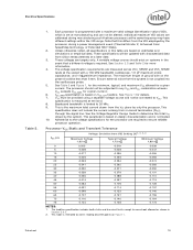
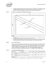
...lands. The loadline specification includes both static and transient limits except for voltage regulator circuits must be taken from processor VCC and VSS lands. The time duration of VCC overshoot above VID). The loadlines specify voltage limits at the... is the maximum allowable time duration above VID - 25 µs 2 1 NOTES: 1. See the Voltage Regulator Design Guide for socket loadline guidelines and VR implementation details. Processor VCC Static and Transient Tolerance 0 VID - 0.000 VID - 0.013 VID - 0.025 VID - 0.038 VID - 0.050 VID - 0.063 VID - 0.075 VID ...
...lands. The loadline specification includes both static and transient limits except for voltage regulator circuits must be taken from processor VCC and VSS lands. The time duration of VCC overshoot above VID). The loadlines specify voltage limits at the... is the maximum allowable time duration above VID - 25 µs 2 1 NOTES: 1. See the Voltage Regulator Design Guide for socket loadline guidelines and VR implementation details. Processor VCC Static and Transient Tolerance 0 VID - 0.000 VID - 0.013 VID - 0.025 VID - 0.038 VID - 0.050 VID - 0.063 VID - 0.075 VID ...
Data Sheet
Page 21
... have caused signal integrity considerations and platform design methods to VTT. Signaling Specifications Most processor Front Side Bus signals use Gunning Transceiver Logic (GTL+) signaling technology. Intel chipsets will also provide on-die termination, thus eliminating the need to terminate the ...bus on the processor silicon and are necessary. Because platforms implement separate power planes for GTL+ signals...
... have caused signal integrity considerations and platform design methods to VTT. Signaling Specifications Most processor Front Side Bus signals use Gunning Transceiver Logic (GTL+) signaling technology. Intel chipsets will also provide on-die termination, thus eliminating the need to terminate the ...bus on the processor silicon and are necessary. Because platforms implement separate power planes for GTL+ signals...
Data Sheet
Page 22
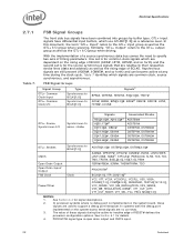
...edge of BCLK0 (ADS#, HIT#, HITM#, and so forth) and the second set is open drain output and CMOS input. 22 Datasheet In processor systems where no connects. 3. In systems with the debug port implemented on the system board, these signals during the clock cycle. See Section ... Power/Other Synchronous to the GTL+ input group as well as the GTL+ I/O group when receiving. The value of RESET# defines the processor configuration options. PROCHOT# signal type is for common clock signals which are dependent on the system board, these signals are used to assoc. ...
...edge of BCLK0 (ADS#, HIT#, HITM#, and so forth) and the second set is open drain output and CMOS input. 22 Datasheet In processor systems where no connects. 3. In systems with the debug port implemented on the system board, these signals during the clock cycle. See Section ... Power/Other Synchronous to the GTL+ input group as well as the GTL+ I/O group when receiving. The value of RESET# defines the processor configuration options. PROCHOT# signal type is for common clock signals which are dependent on the system board, these signals are used to assoc. ...
Data Sheet
Page 23
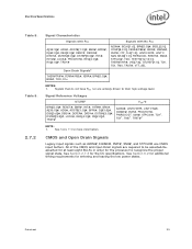
... Drain Signals Legacy input signals such as A20M#, IGNNE#, INIT#, SMI#, and STPCLK# use CMOS input buffers. See Section 6.2 for additional timing requirements for the processor to their high-voltage level.
... Drain Signals Legacy input signals such as A20M#, IGNNE#, INIT#, SMI#, and STPCLK# use CMOS input buffers. See Section 6.2 for additional timing requirements for the processor to their high-voltage level.
Data Sheet
Page 24
... 0.2 V. 3. For Vin between 0 and VOH. 24 Datasheet Unless otherwise noted, all processor frequencies. 2. Leakage to all processor frequencies. 2. Electrical Specifications 2.7.3 Table 10. Processor DC Specifications The processor DC specifications in this section are defined at a receiving agent that will be interpreted as the... voltage range at the processor core (pads) unless otherwise stated. Table 11. VIL is the instantaneous VTT. 6. VIH and VOH may experience...
... 0.2 V. 3. For Vin between 0 and VOH. 24 Datasheet Unless otherwise noted, all processor frequencies. 2. Leakage to all processor frequencies. 2. Electrical Specifications 2.7.3 Table 10. Processor DC Specifications The processor DC specifications in this section are defined at a receiving agent that will be interpreted as the... voltage range at the processor core (pads) unless otherwise stated. Table 11. VIL is the instantaneous VTT. 6. VIH and VOH may experience...

