Data Sheet
Page 2
...specifications. All rights reserved. 2 Datasheet Intel reserves these for future definition and shall have no responsibility whatsoever for more information. Processor numbers differentiate features within each processor family, not across different processor families. Not all specified units of performance. Intel, Pentium, Intel Core, Intel SpeedStep, and the Intel logo are trademarks of this processor support Enhanced Intel... RIGHTS IS GRANTED BY THIS DOCUMENT. The Intel Pentium® dual-core processor E5000 and E6000 series may contain design defects or errors known as...
...specifications. All rights reserved. 2 Datasheet Intel reserves these for future definition and shall have no responsibility whatsoever for more information. Processor numbers differentiate features within each processor family, not across different processor families. Not all specified units of performance. Intel, Pentium, Intel Core, Intel SpeedStep, and the Intel logo are trademarks of this processor support Enhanced Intel... RIGHTS IS GRANTED BY THIS DOCUMENT. The Intel Pentium® dual-core processor E5000 and E6000 series may contain design defects or errors known as...
Data Sheet
Page 3
... Zones 37 3.3 Package Loading Specifications 37 3.4 Package Handling Guidelines 37 3.5 Package Insertion Specifications 38 3.6 Processor Mass Specification 38 3.7 Processor Materials 38 3.8 Processor Markings 38 3.9 Processor Land Coordinates 40 4 Land Listing and Signal Descriptions 41 4.1 Processor Land Assignments 41 4.2 Alphabetical Signals Reference 64 5 Thermal Specifications and Design Considerations 75 5.1 Processor Thermal Specifications 75 5.1.1 Thermal Specifications 75 5.1.2 Thermal Metrology 78 5.2 Processor Thermal Features 78 5.2.1 Thermal...
... Zones 37 3.3 Package Loading Specifications 37 3.4 Package Handling Guidelines 37 3.5 Package Insertion Specifications 38 3.6 Processor Mass Specification 38 3.7 Processor Materials 38 3.8 Processor Markings 38 3.9 Processor Land Coordinates 40 4 Land Listing and Signal Descriptions 41 4.1 Processor Land Assignments 41 4.2 Alphabetical Signals Reference 64 5 Thermal Specifications and Design Considerations 75 5.1 Processor Thermal Specifications 75 5.1.1 Thermal Specifications 75 5.1.2 Thermal Metrology 78 5.2 Processor Thermal Features 78 5.2.1 Thermal...
Data Sheet
Page 4
... State 88 6.2.6 Deep Sleep State 89 6.2.7 Deeper Sleep State 89 6.2.8 Enhanced Intel® SpeedStep® Technology 90 6.3 Processor Power Status Indicator (PSI) Signal 90 7 Boxed Processor Specifications 91 7.1 Introduction ...91 7.2 Mechanical Specifications 92 7.2.1 Boxed Processor Cooling Solution Dimensions 92 7.2.2 Boxed Processor Fan Heatsink Weight 93 7.2.3 Boxed Processor Retention Mechanism and Heatsink Attach Clip Assembly .....93 7.3 Electrical Requirements 93...
... State 88 6.2.6 Deep Sleep State 89 6.2.7 Deeper Sleep State 89 6.2.8 Enhanced Intel® SpeedStep® Technology 90 6.3 Processor Power Status Indicator (PSI) Signal 90 7 Boxed Processor Specifications 91 7.1 Introduction ...91 7.2 Mechanical Specifications 92 7.2.1 Boxed Processor Cooling Solution Dimensions 92 7.2.2 Boxed Processor Fan Heatsink Weight 93 7.2.3 Boxed Processor Retention Mechanism and Heatsink Attach Clip Assembly .....93 7.3 Electrical Requirements 93...
Data Sheet
Page 6
... GTL+ Bus Voltage Definitions 27 15 Core Frequency to FSB Multiplier Configuration 28 16 BSEL[2:0] Frequency Table for BCLK[1:0 29 17 Front Side Bus Differential BCLK Specifications 29 18 FSB Differential Clock Specifications (800 MHz FSB 30 19 FSB Differential Clock Specifications (1066 MHz FSB 30 20 Processor Loading Specifications 37 21 Package Handling Guidelines 37...
... GTL+ Bus Voltage Definitions 27 15 Core Frequency to FSB Multiplier Configuration 28 16 BSEL[2:0] Frequency Table for BCLK[1:0 29 17 Front Side Bus Differential BCLK Specifications 29 18 FSB Differential Clock Specifications (800 MHz FSB 30 19 FSB Differential Clock Specifications (1066 MHz FSB 30 20 Processor Loading Specifications 37 21 Package Handling Guidelines 37...
Data Sheet
Page 10
...; Retention mechanism (RM) - This feature can not use. • Processor core - Dual core processor in which all processor specifications, including DC, AC, system bus, signal quality, mechanical and thermal are explained here for Intel® architecture-based desktop, mobile, and mainstream server multi-core processors. For this document, the term processor is independent of the socket. • FSB (Front Side Bus...
...; Retention mechanism (RM) - This feature can not use. • Processor core - Dual core processor in which all processor specifications, including DC, AC, system bus, signal quality, mechanical and thermal are explained here for Intel® architecture-based desktop, mobile, and mainstream server multi-core processors. For this document, the term processor is independent of the socket. • FSB (Front Side Bus...
Data Sheet
Page 11
... can improve virtualization solutions. More information is at http://developer.intel.com/technology/64bitextensions/. • Enhanced Intel® SpeedStep® Technology - References Document Location Intel® Pentium® Dual-Core Processor E6000 and E5000 Series Specification Update Intel® Core™2 Duo processor E8000 and E7000 Series, and Intel® Pentium® Dual-Core Processor E6000 and E5000 Series Thermal and Mechanical Design Guidelines Voltage...
... can improve virtualization solutions. More information is at http://developer.intel.com/technology/64bitextensions/. • Enhanced Intel® SpeedStep® Technology - References Document Location Intel® Pentium® Dual-Core Processor E6000 and E5000 Series Specification Update Intel® Core™2 Duo processor E8000 and E7000 Series, and Intel® Pentium® Dual-Core Processor E6000 and E5000 Series Thermal and Mechanical Design Guidelines Voltage...
Data Sheet
Page 13
... be connected to its large number of transistors and high internal clock speeds, the processor is not adequate. Contact your Intel field representative for current when entering an idle condition from a running condition. Decoupling ...below their minimum specified values if bulk decoupling is capable of the processor interfaces and signals. VTT Decoupling Decoupling must be designed to satisfy the processor voltage specifications. Electrical Specifications 2 Electrical Specifications 2.1 2.2 2.2.1 2.2.2 This chapter describes the electrical characteristics of generating...
... be connected to its large number of transistors and high internal clock speeds, the processor is not adequate. Contact your Intel field representative for current when entering an idle condition from a running condition. Decoupling ...below their minimum specified values if bulk decoupling is capable of the processor interfaces and signals. VTT Decoupling Decoupling must be designed to satisfy the processor voltage specifications. Electrical Specifications 2 Electrical Specifications 2.1 2.2 2.2.1 2.2.2 This chapter describes the electrical characteristics of generating...
Data Sheet
Page 14
... maximum voltages must also be capable of regulating its associated processor core voltage (VCC). However, additional high frequency capacitance must be provided by the new VID. See the Intel® Pentium® dualcore Processor E6000 and E5000 Series Specification Update for further details on specific valid core frequency and VID values of the high frequency capacitance required...
... maximum voltages must also be capable of regulating its associated processor core voltage (VCC). However, additional high frequency capacitance must be provided by the new VID. See the Intel® Pentium® dualcore Processor E6000 and E5000 Series Specification Update for further details on specific valid core frequency and VID values of the high frequency capacitance required...

Data Sheet
Page 15
Electrical Specifications Table 2. Voltage Identification Definition VID VID VID VID VID VID VID VID 76543210 Voltage 00000000 OFF 00000010 1.6 0 0 0 0 0 1 0 0 1.5875 0 0 0 0 0 1 1 0 1.575 0 0 0 0 1 0 0 0 1.5625 00001010 1.55 0 0 0 0 1 1 0 0 1.5375 0 0 0 0 1 1 1 0 1.525 0 0 0 1 0 0 0 0 1.5125 ...
Electrical Specifications Table 2. Voltage Identification Definition VID VID VID VID VID VID VID VID 76543210 Voltage 00000000 OFF 00000010 1.6 0 0 0 0 0 1 0 0 1.5875 0 0 0 0 0 1 1 0 1.575 0 0 0 0 1 0 0 0 1.5625 00001010 1.55 0 0 0 0 1 1 0 0 1.5375 0 0 0 0 1 1 1 0 1.525 0 0 0 1 0 0 0 0 1.5125 ...
Data Sheet
Page 16
... signals Terminating multiple TESTHI pins together with a single pull-up resistors or be terminated on -die termination has been included by the processor to allow for system testability. When tying any other signal (including each group: • TESTHI[1:0] • TESTHI[7:2] • ...have a resistance value within ± 20% of the impedance of the motherboard trace for a land listing of the processor and the location of supplying. Electrical Specifications 2.4 2.5 Reserved, Unused, and TESTHI Signals All RESERVED lands must be grouped with other ) can be grouped with ...
... signals Terminating multiple TESTHI pins together with a single pull-up resistors or be terminated on -die termination has been included by the processor to allow for system testability. When tying any other signal (including each group: • TESTHI[1:0] • TESTHI[7:2] • ...have a resistance value within ± 20% of the impedance of the motherboard trace for a land listing of the processor and the location of supplying. Electrical Specifications 2.4 2.5 Reserved, Unused, and TESTHI Signals All RESERVED lands must be grouped with other ) can be grouped with ...
Data Sheet
Page 17
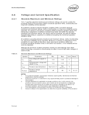
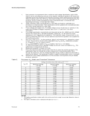
...Core voltage with respect to VSS -0.3 VTT FSB termination voltage with its reliability will not affect the long-term reliability of the processor. Storage within the functional operating condition limits, it will either not function, or its lifetime degraded depending on any length of the processor. For functional operation, see the processor case temperature specifications...this specification can be severely degraded. Electrical Specifications 2.6 2.6.1 Table 3. For functional operation, all processor electrical, signal quality, mechanical and thermal specifications ...
...Core voltage with respect to VSS -0.3 VTT FSB termination voltage with its reliability will not affect the long-term reliability of the processor. Storage within the functional operating condition limits, it will either not function, or its lifetime degraded depending on any length of the processor. For functional operation, see the processor case temperature specifications...this specification can be severely degraded. Electrical Specifications 2.6 2.6.1 Table 3. For functional operation, all processor electrical, signal quality, mechanical and thermal specifications ...
Data Sheet
Page 18
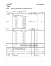
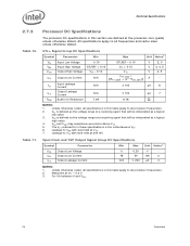
Voltage and Current Specifications Symbol Parameter Min Typ Max Unit Notes2, 10 VID Range VID 0.8500 - 1.3625 V Core VCC Processor Number (2 MB Cache): VCC for 775_VR_CONFIG_06: E6800 3.33 GHz E6700 3.20 GHz E6600 3.06 GHz E6500 2.93 GHz E6300 2.80 GHz See Table 5, Figure 1 V E5200 2.50 GHz...75 E6300 E5200 2.80 GHz 2.50 GHz - - 75 A 75 E5300 2.66 GHz 75 E5400 2.70 GHz 75 E5500 2.80 GHz 75 E5700 3.00 GHz 75 E5800 3.20 GHz 75 FSB termination voltage on Intel 3 series Chipset family boards 1.045 1.1 1.155 VTT (DC + AC specifications) on Intel ...
Voltage and Current Specifications Symbol Parameter Min Typ Max Unit Notes2, 10 VID Range VID 0.8500 - 1.3625 V Core VCC Processor Number (2 MB Cache): VCC for 775_VR_CONFIG_06: E6800 3.33 GHz E6700 3.20 GHz E6600 3.06 GHz E6500 2.93 GHz E6300 2.80 GHz See Table 5, Figure 1 V E5200 2.50 GHz...75 E6300 E5200 2.80 GHz 2.50 GHz - - 75 A 75 E5300 2.66 GHz 75 E5400 2.70 GHz 75 E5500 2.80 GHz 75 E5700 3.00 GHz 75 E5800 3.20 GHz 75 FSB termination voltage on Intel 3 series Chipset family boards 1.045 1.1 1.155 VTT (DC + AC specifications) on Intel ...
Data Sheet
Page 19
... except for a given current. 6. Individual maximum VID values are required to VCC. Electrical Specifications Table 5. 1. See Section 2.3 and Table 2 for the processor are calibrated during a power management event (Thermal Monitor 2, Enhanced Intel SpeedStep technology, or Extended HALT State). 2. Each processor is programmed with characterized data from the system is the maximum total current drawn...
... except for a given current. 6. Individual maximum VID values are required to VCC. Electrical Specifications Table 5. 1. See Section 2.3 and Table 2 for the processor are calibrated during a power management event (Thermal Monitor 2, Enhanced Intel SpeedStep technology, or Extended HALT State). 2. Each processor is programmed with characterized data from the system is the maximum total current drawn...
Data Sheet
Page 20
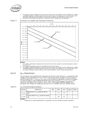
...Design Guide for socket loadline guidelines and VR implementation details. 4. Adherence to these specifications is required to ensure reliable processor operation. 20 Datasheet Voltage regulation feedback for voltage regulator circuits must be taken from a high to ...the processor die voltage as shown in Section 2.6.3. 2. Adherence to this loadline specification is required to ensure reliable processor operation. This loadline specification shows the deviation from processor VCC and VSS lands. VCC Overshoot The processor can tolerate short transient ...
...Design Guide for socket loadline guidelines and VR implementation details. 4. Adherence to these specifications is required to ensure reliable processor operation. 20 Datasheet Voltage regulation feedback for voltage regulator circuits must be taken from a high to ...the processor die voltage as shown in Section 2.6.3. 2. Adherence to this loadline specification is required to ensure reliable processor operation. This loadline specification shows the deviation from processor VCC and VSS lands. VCC Overshoot The processor can tolerate short transient ...
Data Sheet
Page 21
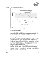
...Logic (GTL+) signaling technology. This configuration allows for GTL+ signals are provided on processor must meet the specifications in duration may be taken with previous processor families. Speed enhancements to data and address busses have caused signal integrity considerations and... for GTLREF specifications). Intel chipsets will also provide on-die termination, thus eliminating the need to determine if a signal is measured overshoot voltage. 2. TOS is measured time duration above VID 2.6.4 2.7 NOTES: 1. Die Voltage Validation Overshoot events on the processor silicon and ...
...Logic (GTL+) signaling technology. This configuration allows for GTL+ signals are provided on processor must meet the specifications in duration may be taken with previous processor families. Speed enhancements to data and address busses have caused signal integrity considerations and... for GTLREF specifications). Intel chipsets will also provide on-die termination, thus eliminating the need to determine if a signal is measured overshoot voltage. 2. TOS is measured time duration above VID 2.6.4 2.7 NOTES: 1. Die Voltage Validation Overshoot events on the processor silicon and ...
Data Sheet
Page 22
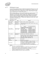
... at any time during the active-to support a debug port interposer. Table 7. In processor systems where no connects. 3. The value of RESET# defines the processor configuration options. With the implementation of BCLK0 (ADS#, HIT#, HITM#, and so forth)...VTT_OUT_RIGHT, VTT_SEL, FCx, PECI, MSID[1:0] NOTES: 1. Similarly, "GTL+ Output" refers to assoc. See Section 6.1 for details. 4. Electrical Specifications 2.7.1 FSB Signal Groups The front side bus signals have differential input buffers, which use GTLREF[1:0] as a reference level. FSB Signal Groups Signal ...
... at any time during the active-to support a debug port interposer. Table 7. In processor systems where no connects. 3. The value of RESET# defines the processor configuration options. With the implementation of BCLK0 (ADS#, HIT#, HITM#, and so forth)...VTT_OUT_RIGHT, VTT_SEL, FCx, PECI, MSID[1:0] NOTES: 1. Similarly, "GTL+ Output" refers to assoc. See Section 6.1 for details. 4. Electrical Specifications 2.7.1 FSB Signal Groups The front side bus signals have differential input buffers, which use GTLREF[1:0] as a reference level. FSB Signal Groups Signal ...
Data Sheet
Page 23
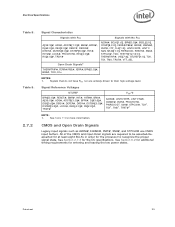
...#, INIT#, PROCHOT#, PWRGOOD1, SMI#, STPCLK#, TCK1, TDI1, TMS1, TRST#1 NOTE: 1. See Section 6.2 for additional timing requirements for the DC specifications. Datasheet 23 See Table 11 for the processor to their high-voltage level. Electrical Specifications . Table 8. All of the CMOS and Open Drain signals are actively driven to recognize the proper signal state.
...#, INIT#, PROCHOT#, PWRGOOD1, SMI#, STPCLK#, TCK1, TDI1, TMS1, TRST#1 NOTE: 1. See Section 6.2 for additional timing requirements for the DC specifications. Datasheet 23 See Table 11 for the processor to their high-voltage level. Electrical Specifications . Table 8. All of the CMOS and Open Drain signals are actively driven to recognize the proper signal state.
Data Sheet
Page 24
... agent that will be interpreted as a logical low value. 3. Measured at the processor core (pads) unless otherwise stated. Leakage to VTT with land held at a receiving agent that will be interpreted as a logical high value. 4. GTL+ Signal Group DC Specifications Symbol Parameter Min Max Unit Notes1 VIL Input Low Voltage -0.10 GTLREF - 0.10...
... agent that will be interpreted as a logical low value. 3. Measured at the processor core (pads) unless otherwise stated. Leakage to VTT with land held at a receiving agent that will be interpreted as a logical high value. 4. GTL+ Signal Group DC Specifications Symbol Parameter Min Max Unit Notes1 VIL Input Low Voltage -0.10 GTLREF - 0.10...

Data Sheet
Page 25
... voltage range at a receiving agent that will be found in the Platform Environment Control Interface (PECI) Specification. IOH is measured at a receiving agent that provides a communication channel between Intel processors, chipsets, and external thermal monitoring devices. The processor contains Digital Thermal Sensors (DTS) distributed throughout die. Datasheet 25 VIH and VOH may be interpreted...
... voltage range at a receiving agent that will be found in the Platform Environment Control Interface (PECI) Specification. IOH is measured at a receiving agent that provides a communication channel between Intel processors, chipsets, and external thermal monitoring devices. The processor contains Digital Thermal Sensors (DTS) distributed throughout die. Datasheet 25 VIH and VOH may be interpreted...

Data Sheet
Page 26
... should be generated on the PECI bus. 3. One node is counted for each client and one node for VTT specifications. 2. Electrical Specifications Table 13. . 2.7.3.2 PECI DC Electrical Limits Symbol Definition and Conditions Min Max Units Notes1 Vin Input Voltage Range ...Vhysteresis Hysteresis -0.15 VTT V 0.1 * VTT - Vp-p NOTES: 1. Valid high and low levels are integrated into the processor silicon. V 2 Vn Negative...
... should be generated on the PECI bus. 3. One node is counted for each client and one node for VTT specifications. 2. Electrical Specifications Table 13. . 2.7.3.2 PECI DC Electrical Limits Symbol Definition and Conditions Min Max Units Notes1 Vin Input Voltage Range ...Vhysteresis Hysteresis -0.15 VTT V 0.1 * VTT - Vp-p NOTES: 1. Valid high and low levels are integrated into the processor silicon. V 2 Vn Negative...