Data Sheet
Page 5
... for the Boxed Processor 93 23 Boxed Processor Fan Heatsink Power Cable Connector Description 94 24 Baseboard Power Header Placement Relative to Processor Socket 95 25 Boxed Processor Fan Heatsink Airspace Keepout Requirements (side 1 view 96 26 Boxed Processor Fan Heatsink Airspace Keepout... 82 18 Processor Low Power State Machine 86 19 Mechanical Representation of 3 36 9 Intel® Pentium® Dual-Core Processor E5000 Series Top-Side Markings Example 38 10 Intel® Pentium® Dual-Core Processor E6000 Series Top-Side Markings Example 39 11 Processor Land Coordinates ...
... for the Boxed Processor 93 23 Boxed Processor Fan Heatsink Power Cable Connector Description 94 24 Baseboard Power Header Placement Relative to Processor Socket 95 25 Boxed Processor Fan Heatsink Airspace Keepout Requirements (side 1 view 96 26 Boxed Processor Fan Heatsink Airspace Keepout... 82 18 Processor Low Power State Machine 86 19 Mechanical Representation of 3 36 9 Intel® Pentium® Dual-Core Processor E5000 Series Top-Side Markings Example 38 10 Intel® Pentium® Dual-Core Processor E6000 Series Top-Side Markings Example 39 11 Processor Land Coordinates ...
Data Sheet
Page 9
...; dual-core processor E6000 series refers to as the LGA775 socket. The Intel® Pentium® dual-core processor E6000 series supports Intel® Virtualization Technology (Intel® VT). Conversely, when NMI is inverted. In this document, the Intel® Pentium® dual-core processor E6000 and E5000 series may be referred to the Intel® Pentium® dual-core processor E6800, E6700, E6600, E6500 and E6300. The processor's front...
...; dual-core processor E6000 series refers to as the LGA775 socket. The Intel® Pentium® dual-core processor E6000 series supports Intel® Virtualization Technology (Intel® VT). Conversely, when NMI is inverted. In this document, the Intel® Pentium® dual-core processor E6000 and E5000 series may be referred to the Intel® Pentium® dual-core processor E6800, E6700, E6600, E6500 and E6300. The processor's front...
Data Sheet
Page 10
... a 2 MB L2 cache. • Intel® Pentium® dual-core processor E6000 series - Dual core processor in which all processor specifications, including DC, AC, system bus, signal quality, mechanical and thermal are explained here for Intel® architecture-based desktop, mobile, and mainstream server multi-core processors. Component thermal solutions interface with integrated L2 cache. • LGA775 socket - Dual core processor in non-executable memory...
... a 2 MB L2 cache. • Intel® Pentium® dual-core processor E6000 series - Dual core processor in which all processor specifications, including DC, AC, system bus, signal quality, mechanical and thermal are explained here for Intel® architecture-based desktop, mobile, and mainstream server multi-core processors. Component thermal solutions interface with integrated L2 cache. • LGA775 socket - Dual core processor in non-executable memory...
Data Sheet
Page 11
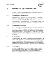
.... References Document Location Intel® Pentium® Dual-Core Processor E6000 and E5000 Series Specification Update Intel® Core™2 Duo processor E8000 and E7000 Series, and Intel® Pentium® Dual-Core Processor E6000 and E5000 Series Thermal and Mechanical Design Guidelines Voltage Regulator-Down (VRD) 11.0 Processor Power Delivery Design Guidelines For Desktop LGA775 Socket LGA775 Socket Mechanical Design Guide Intel® 64 and...
.... References Document Location Intel® Pentium® Dual-Core Processor E6000 and E5000 Series Specification Update Intel® Core™2 Duo processor E8000 and E7000 Series, and Intel® Pentium® Dual-Core Processor E6000 and E5000 Series Thermal and Mechanical Design Guidelines Voltage Regulator-Down (VRD) 11.0 Processor Power Delivery Design Guidelines For Desktop LGA775 Socket LGA775 Socket Mechanical Design Guide Intel® 64 and...
Data Sheet
Page 13
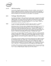
...reduced lifetime of an idle condition. DC electrical characteristics are required to satisfy the processor voltage specifications. A separate supply must be connected to a system ground plane. Contact your Intel field representative for current when entering an idle condition from a running condition. The... type, power plane and trace sizing, and component placement. Consult the Voltage Regulator-Down (VRD) 11.0 Processor Power Delivery Design Guidelines For Desktop LGA775 Socket for on power planes to the I/O buffers. All power lands must be connected to meet the expected load...
...reduced lifetime of an idle condition. DC electrical characteristics are required to satisfy the processor voltage specifications. A separate supply must be connected to a system ground plane. Contact your Intel field representative for current when entering an idle condition from a running condition. The... type, power plane and trace sizing, and component placement. Consult the Voltage Regulator-Down (VRD) 11.0 Processor Power Delivery Design Guidelines For Desktop LGA775 Socket for on power planes to the I/O buffers. All power lands must be connected to meet the expected load...
Data Sheet
Page 14
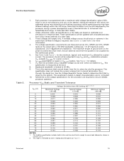
...Sleep State the platform must also be noted that two devices at the same core speed may result in as many VID transitions as measured across the VCC_SENSE and VSS_SENSE lands. If the processor socket is empty (VID[7:0] = 11111110), or the voltage regulation circuit cannot supply ... VR output voltage to reach the target core voltage. The Deeper Sleep State also requires additional platform support. See the Intel® Pentium® dualcore Processor E6000 and E5000 Series Specification Update for further details on specific valid core frequency and VID values of the high frequency...
...Sleep State the platform must also be noted that two devices at the same core speed may result in as many VID transitions as measured across the VCC_SENSE and VSS_SENSE lands. If the processor socket is empty (VID[7:0] = 11111110), or the voltage regulation circuit cannot supply ... VR output voltage to reach the target core voltage. The Deeper Sleep State also requires additional platform support. See the Intel® Pentium® dualcore Processor E6000 and E5000 Series Specification Update for further details on specific valid core frequency and VID values of the high frequency...
Data Sheet
Page 19
... in Section 2.6.3. 2. Datasheet 19 Individual maximum VID values are calibrated during a power management event (Thermal Monitor 2, Enhanced Intel SpeedStep technology, or Extended HALT State). 2. These voltages are required to the voltage specifications for details. 7. The voltage ... does not include the current coming from silicon measurements at the socket with a maximum valid voltage identification value (VID), which is measured at the land. 8. Adherence to ensure reliable processor operation. The loadline specification includes both static and transient limits except...
... in Section 2.6.3. 2. Datasheet 19 Individual maximum VID values are calibrated during a power management event (Thermal Monitor 2, Enhanced Intel SpeedStep technology, or Extended HALT State). 2. These voltages are required to the voltage specifications for details. 7. The voltage ... does not include the current coming from silicon measurements at the socket with a maximum valid voltage identification value (VID), which is measured at the land. 8. Adherence to ensure reliable processor operation. The loadline specification includes both static and transient limits except...
Data Sheet
Page 20
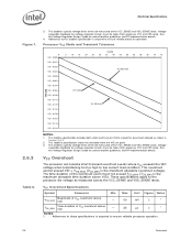
... for voltage regulator circuits must be taken from a high to ensure reliable processor operation. This overshoot cannot exceed VID + VOS_MAX (VOS_MAX is required to the processor die voltage as shown in Section 2.6.3. 2. The loadline specification includes both static... Time duration of the overshoot event must be taken from the VID set point. 3. See the Voltage Regulator Design Guide for socket loadline guidelines and VR implementation details. Adherence to these specifications is the maximum allowable overshoot voltage). Electrical Specifications Figure 1. 2.6.3 Table...
... for voltage regulator circuits must be taken from a high to ensure reliable processor operation. This overshoot cannot exceed VID + VOS_MAX (VOS_MAX is required to the processor die voltage as shown in Section 2.6.3. 2. The loadline specification includes both static... Time duration of the overshoot event must be taken from the VID set point. 3. See the Voltage Regulator Design Guide for socket loadline guidelines and VR implementation details. Adherence to these specifications is the maximum allowable overshoot voltage). Electrical Specifications Figure 1. 2.6.3 Table...
Data Sheet
Page 33
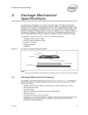
... consists of the processor package components and how they are shown in the processor thermal and mechanical design guidelines. Figure 5 shows a sketch of a processor core mounted on the LGA775 socket. Datasheet 33 See the LGA775 Socket Mechanical Design Guide for the processor. An integrated heat... The drawings include dimensions necessary to the package substrate and core, and serves as the mating surface for reference and are included for processor component thermal solutions, such as a heatsink. Socket and motherboard are not part of the cooling solution is ...
... consists of the processor package components and how they are shown in the processor thermal and mechanical design guidelines. Figure 5 shows a sketch of a processor core mounted on the LGA775 socket. Datasheet 33 See the LGA775 Socket Mechanical Design Guide for the processor. An integrated heat... The drawings include dimensions necessary to the package substrate and core, and serves as the mating surface for reference and are included for processor component thermal solutions, such as a heatsink. Socket and motherboard are not part of the cooling solution is ...

Data Sheet
Page 37
... lbf] 1, 4 Tensile 111 N [25 lbf] 2, 4 Torque 3.95 N-m [35 lbf-in a direction normal to a fixed substrate. These guidelines are based on the processor package. 3. The location and quantity of the processor socket. 4. The minimum loading specification must also provide the minimum specified load on limited testing for keep -out zones. These specifications are based...
... lbf] 1, 4 Tensile 111 N [25 lbf] 2, 4 Torque 3.95 N-m [35 lbf-in a direction normal to a fixed substrate. These guidelines are based on the processor package. 3. The location and quantity of the processor socket. 4. The minimum loading specification must also provide the minimum specified load on limited testing for keep -out zones. These specifications are based...
Data Sheet
Page 38
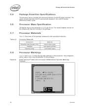
... to aid in the identification of the package components and associated materials. Intel® Pentium® Dual-Core Processor E5000 Series Top-Side Markings Example INTEL ©M'06 E5200 Intel® Pentium® Dual-Core SLAY7 [COO] 2.50GHZ/2M/800/06 [FPO] e4 ATPO S/N 38 Datasheet The socket should meet the LGA775 requirements detailed in the package. 3.7 Table 22...
... to aid in the identification of the package components and associated materials. Intel® Pentium® Dual-Core Processor E5000 Series Top-Side Markings Example INTEL ©M'06 E5200 Intel® Pentium® Dual-Core SLAY7 [COO] 2.50GHZ/2M/800/06 [FPO] e4 ATPO S/N 38 Datasheet The socket should meet the LGA775 requirements detailed in the package. 3.7 Table 22...

Data Sheet
Page 40
Figure 11. Processor Land Coordinates and Quadrants, Top View V /V CC SS 30 29 28 27 26 25 24 23 22 21 20 19 18 17 16 15 14 13 12 11 10 9 8 7 6 5 4 3 2 1 AN AM AL AK AJ AH AG AF AE AD AC AB AA Y W V Socket 775 U T Quadrants R P Top View N M L...AB AA Y W Address/ V U Common Clock/ T Async R P N M L K J H G F E D C B A § 40 Datasheet Package Mechanical Specifications 3.9 Processor Land Coordinates . Figure 11 shows the top view of the processor land coordinates. The coordinates are referred to throughout the document to identify...
Figure 11. Processor Land Coordinates and Quadrants, Top View V /V CC SS 30 29 28 27 26 25 24 23 22 21 20 19 18 17 16 15 14 13 12 11 10 9 8 7 6 5 4 3 2 1 AN AM AL AK AJ AH AG AF AE AD AC AB AA Y W V Socket 775 U T Quadrants R P Top View N M L...AB AA Y W Address/ V U Common Clock/ T Async R P N M L K J H G F E D C B A § 40 Datasheet Package Mechanical Specifications 3.9 Processor Land Coordinates . Figure 11 shows the top view of the processor land coordinates. The coordinates are referred to throughout the document to identify...

Data Sheet
Page 70
... come within specification. A number of bus signals are turned on Reset, RESET# must connect the appropriate pins/lands of all processor FSB agents. These configuration options are source synchronous to protect internal circuits against voltage sequencing issues. Connection of these lands to VCC...PWRGOOD is used to ADSTB0#. On observing active RESET#, all processor FSB agents. This signal does not have reached their specifications. 'Clean' implies that the signal will deassert their contents. SKTOCC# (Socket Occupied) will be driven high throughout boundary scan operation. ...
... come within specification. A number of bus signals are turned on Reset, RESET# must connect the appropriate pins/lands of all processor FSB agents. These configuration options are source synchronous to protect internal circuits against voltage sequencing issues. Connection of these lands to VCC...PWRGOOD is used to ADSTB0#. On observing active RESET#, all processor FSB agents. This signal does not have reached their specifications. 'Clean' implies that the signal will deassert their contents. SKTOCC# (Socket Occupied) will be driven high throughout boundary scan operation. ...

Data Sheet
Page 93
...-mounted fan speed monitor requirements, if applicable. The power cable connector and pinout are shown in the baseboard socket. The fan heatsink receives a PWM signal from the motherboard from a power header on the processor weight and heatsink requirements. Table 30 contains specifications for details on the baseboard. collector output that is optional...
...-mounted fan speed monitor requirements, if applicable. The power cable connector and pinout are shown in the baseboard socket. The fan heatsink receives a PWM signal from the motherboard from a power header on the processor weight and heatsink requirements. Table 30 contains specifications for details on the baseboard. collector output that is optional...

Data Sheet
Page 94
... Figure 23. Figure 24 shows the location of the processor socket. Fan Heatsink Power and Signal Specifications Description Min Typ +12 V: 12 volt... with polarizing ribs and friction locking ramp. 0.100" pitch, 0.025" square pin width. A A - The boxed processor's fan heatsink requires a constant +12 V supplied to reach it. The baseboard power header should be documented in the ...] from the center of the fan power connector relative to the processor socket. The power header identification and location should pull this signal to 5 V with a resistor. 2.
... Figure 23. Figure 24 shows the location of the processor socket. Fan Heatsink Power and Signal Specifications Description Min Typ +12 V: 12 volt... with polarizing ribs and friction locking ramp. 0.100" pitch, 0.025" square pin width. A A - The boxed processor's fan heatsink requires a constant +12 V supplied to reach it. The baseboard power header should be documented in the ...] from the center of the fan power connector relative to the processor socket. The power header identification and location should pull this signal to 5 V with a resistor. 2.

Data Sheet
Page 95
...integrator. Airspace is unimpeded. Blocking the airflow to the fan heatsink is required around the fan to keep the processor temperature within the specifications (see Table 26) in Chapter 5. Figure 25 and Figure 26 illustrate an acceptable ...heatsink solution used by the boxed processor. Boxed Processor Cooling Requirements The boxed processor may be kept below 38 ºC. However, meeting the processor temperature specification is critical that provide good thermal management. Baseboard Power Header Placement Relative to Processor Socket R110 [4.33] B C 7.4...
...integrator. Airspace is unimpeded. Blocking the airflow to the fan heatsink is required around the fan to keep the processor temperature within the specifications (see Table 26) in Chapter 5. Figure 25 and Figure 26 illustrate an acceptable ...heatsink solution used by the boxed processor. Boxed Processor Cooling Requirements The boxed processor may be kept below 38 ºC. However, meeting the processor temperature specification is critical that provide good thermal management. Baseboard Power Header Placement Relative to Processor Socket R110 [4.33] B C 7.4...
Data Sheet
Page 99
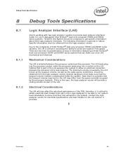
... the complexity of the FSB; Cabling that their logic analyzer interfaces. The LAI lands plug into the processor socket, while the processor lands plug into a socket on the LAI. If this is general in debugging Intel Pentium® dual-core processor E5000 and E6000 series systems. Tektronix and Agilent should be able to run system level simulations to...
... the complexity of the FSB; Cabling that their logic analyzer interfaces. The LAI lands plug into the processor socket, while the processor lands plug into a socket on the LAI. If this is general in debugging Intel Pentium® dual-core processor E5000 and E6000 series systems. Tektronix and Agilent should be able to run system level simulations to...
