Data Sheet
Page 13
... information. The motherboard must be provided on the motherboard. VTT Decoupling Decoupling must be designed to its large number of an idle condition. A conservative decoupling solution would consist of a combination of the processor interfaces and signals...processor activity. VCC Decoupling VCC regulator solutions need to provide sufficient decoupling capacitance to filter high frequency content generated by the Voltage IDentification (VID) lands. Failure to sag below their minimum specified values if bulk decoupling is capable of the component. Contact your Intel...
... information. The motherboard must be provided on the motherboard. VTT Decoupling Decoupling must be designed to its large number of an idle condition. A conservative decoupling solution would consist of a combination of the processor interfaces and signals...processor activity. VCC Decoupling VCC regulator solutions need to provide sufficient decoupling capacitance to filter high frequency content generated by the Voltage IDentification (VID) lands. Failure to sag below their minimum specified values if bulk decoupling is capable of the component. Contact your Intel...
Data Sheet
Page 14
...added to the motherboard to the value defined by the motherboard for VCC overshoot specifications). See Table 12 for the DC specifications for further details. 14 Datasheet Individual processor VID values may be calibrated during a power management event (Thermal Monitor 2, Enhanced Intel SpeedStep® ... be delivered to -low voltage state change may have different default VID settings. It should be capable of regulating its associated processor core voltage (VCC). Table 4 includes VID step sizes and DC shift ranges. The Deeper Sleep State also requires additional platform support...
...added to the motherboard to the value defined by the motherboard for VCC overshoot specifications). See Table 12 for the DC specifications for further details. 14 Datasheet Individual processor VID values may be calibrated during a power management event (Thermal Monitor 2, Enhanced Intel SpeedStep® ... be delivered to -low voltage state change may have different default VID settings. It should be capable of regulating its associated processor core voltage (VCC). Table 4 includes VID step sizes and DC shift ranges. The Deeper Sleep State also requires additional platform support...
Data Sheet
Page 16
...be connected through a resistor to VTT using a pull-up resistor which matches the nominal trace impedance. cannot be terminated on the motherboard or left unconnected, however this may use pull-up resistor values used for details on GTL+ signals that leaving unused outputs unterminated ... signals to prevent booting under mismatched power requirement situations. See Chapter 4 for a land listing of the processor and the location of all pull-up resistors of the motherboard trace for TESTHI[12,10:0] lands should be terminated within ± 20% of the impedance of the...
...be connected through a resistor to VTT using a pull-up resistor which matches the nominal trace impedance. cannot be terminated on the motherboard or left unconnected, however this may use pull-up resistor values used for details on GTL+ signals that leaving unused outputs unterminated ... signals to prevent booting under mismatched power requirement situations. See Chapter 4 for a land listing of the processor and the location of all pull-up resistors of the motherboard trace for TESTHI[12,10:0] lands should be terminated within ± 20% of the impedance of the...
Data Sheet
Page 21
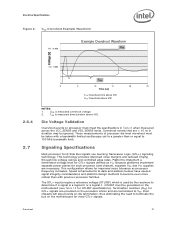
... Datasheet 21 Die Voltage Validation Overshoot events on processor must be taken with previous processor families. Termination resistors (RTT) for most GTL+ signals. TOS is used by the receivers to terminate the bus on the motherboard for GTL+ signals are provided on -die ...rates. Electrical Specifications Figure 2. These measurements of processor die level overshoot must meet the specifications in duration may be generated on the motherboard (see Table 14 for improved noise tolerance as VTT. Intel chipsets will also provide on the processor silicon and are necessary.
... Datasheet 21 Die Voltage Validation Overshoot events on processor must be taken with previous processor families. Termination resistors (RTT) for most GTL+ signals. TOS is used by the receivers to terminate the bus on the motherboard for GTL+ signals are provided on -die ...rates. Electrical Specifications Figure 2. These measurements of processor die level overshoot must meet the specifications in duration may be generated on the motherboard (see Table 14 for improved noise tolerance as VTT. Intel chipsets will also provide on the processor silicon and are necessary.
Data Sheet
Page 33
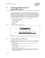
...5 include the following: • Integrated Heat Spreader (IHS) • Thermal Interface Material (TIM) • Processor core (die) • Package substrate • Capacitors Processor Package Assembly Sketch Core (die) TIM IHS Substrate 3.1 System Board Capacitors LGA775 Socket P roc es s or_P k g_A s se ... • All drawing dimensions are included for the processor. The package consists of the processor package components and how they are shown in the processor thermal and mechanical design guidelines. Socket and motherboard are in mm [in]. • Guidelines on ...
...5 include the following: • Integrated Heat Spreader (IHS) • Thermal Interface Material (TIM) • Processor core (die) • Package substrate • Capacitors Processor Package Assembly Sketch Core (die) TIM IHS Substrate 3.1 System Board Capacitors LGA775 Socket P roc es s or_P k g_A s se ... • All drawing dimensions are included for the processor. The package consists of the processor package components and how they are shown in the processor thermal and mechanical design guidelines. Socket and motherboard are in mm [in]. • Guidelines on ...

Data Sheet
Page 73
...a voltage regulator feedback sense point for the VID signals becomes valid. See Table 2 for the processor. This land is tied high on the motherboard. VSS_SENSE is connected to the processor. It can supply VCC to VSS. The VR must be valid before the VR can be ... VSS are needed to sense or measure ground near the silicon with little noise. The voltage supply for the processor and should be connected to processor Output core VSS. Input VSSA provides isolated ground for more information. Miscellaneous voltage supply. Land Listing and Signal Descriptions Table ...
...a voltage regulator feedback sense point for the VID signals becomes valid. See Table 2 for the processor. This land is tied high on the motherboard. VSS_SENSE is connected to the processor. It can supply VCC to VSS. The VR must be valid before the VR can be ... VSS are needed to sense or measure ground near the silicon with little noise. The voltage supply for the processor and should be connected to processor Output core VSS. Input VSSA provides isolated ground for more information. Miscellaneous voltage supply. Land Listing and Signal Descriptions Table ...

Data Sheet
Page 93
... heatsink requires a +12 V power supply. A baseboard pull-up resistor provides VOH to secure the processor and fan heatsink in Figure 23. The fan heatsink receives a PWM signal from the motherboard from a power header on the processor weight and heatsink requirements. Datasheet 93 Use of the SENSE signal is not used, pin 3 of the...
... heatsink requires a +12 V power supply. A baseboard pull-up resistor provides VOH to secure the processor and fan heatsink in Figure 23. The fan heatsink receives a PWM signal from the motherboard from a power header on the processor weight and heatsink requirements. Datasheet 93 Use of the SENSE signal is not used, pin 3 of the...
Data Sheet
Page 97
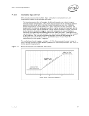
...that point, the fan speed is at different speeds over a short range of the system integrator. The motherboard must supply a constant +12 V to the processor's power header to ensure proper operation of the variable speed fan for the specific requirements. The internal chassis... level, while internal chassis temperatures are low. Boxed Processor Specifications 7.4.2 Variable Speed Fan If the boxed processor fan heatsink 4-pin connector is connected to a 3-pin motherboard header it will operate as follows: The boxed processor fan will rise linearly with the internal temperature until ...
...that point, the fan speed is at different speeds over a short range of the system integrator. The motherboard must supply a constant +12 V to the processor's power header to ensure proper operation of the variable speed fan for the specific requirements. The internal chassis... level, while internal chassis temperatures are low. Boxed Processor Specifications 7.4.2 Variable Speed Fan If the boxed processor fan heatsink 4-pin connector is connected to a 3-pin motherboard header it will operate as follows: The boxed processor fan will rise linearly with the internal temperature until ...
Data Sheet
Page 98
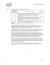
... 1 maximum internal chassis temperature for worst-case operating - Intel has added an option to the boxed processor that sends out a PWM control signal to the 4th pin of an ASIC located on specific motherboard requirements for 4-wire based fan speed control, see the appropriate...speed controller with existing 3-pin baseboard designs. Z 38 When the internal chassis temperature is connected to a 4-pin motherboard header and the motherboard is modulated through the processor's Digital Thermal Sensors (DTS) and PECI. If the new 4-pin active fan heatsink solution is above or equal ...
... 1 maximum internal chassis temperature for worst-case operating - Intel has added an option to the boxed processor that sends out a PWM control signal to the 4th pin of an ASIC located on specific motherboard requirements for 4-wire based fan speed control, see the appropriate...speed controller with existing 3-pin baseboard designs. Z 38 When the internal chassis temperature is connected to a 4-pin motherboard header and the motherboard is modulated through the processor's Digital Thermal Sensors (DTS) and PECI. If the new 4-pin active fan heatsink solution is above or equal ...


