Data Sheet
Page 2
... IMPLIED, BY ESTOPPEL OR OTHERWISE, TO ANY INTELLECTUAL PROPERTY RIGHTS IS GRANTED BY THIS DOCUMENT. Intel may require a BIOS update. The Intel Pentium® dual-core processor E5000 and E6000 series may not be claimed as errata which processors support Intel 64 or consult with a processor, chipset, BIOS, operating system, device drivers and applications enabled for more information...
... IMPLIED, BY ESTOPPEL OR OTHERWISE, TO ANY INTELLECTUAL PROPERTY RIGHTS IS GRANTED BY THIS DOCUMENT. Intel may require a BIOS update. The Intel Pentium® dual-core processor E5000 and E6000 series may not be claimed as errata which processors support Intel 64 or consult with a processor, chipset, BIOS, operating system, device drivers and applications enabled for more information...
Data Sheet
Page 3
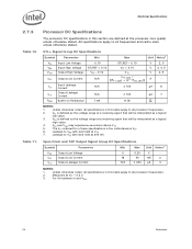
... 2.6.4 Die Voltage Validation 21 2.7 Signaling Specifications 21 2.7.1 FSB Signal Groups 22 2.7.2 CMOS and Open Drain Signals 23 2.7.3 Processor DC Specifications 24 2.7.3.1 Platform Environment Control Interface (PECI) DC Specifications..... 25 2.7.3.2 GTL+ Front Side Bus Specifications 26 2.8 ...Clock Specifications 27 2.8.1 Front Side Bus Clock (BCLK[1:0]) and Processor Clocking 27 2.8.2 FSB Frequency Select Signals (BSEL[2:0 28 2.8.3 Phase Lock Loop (PLL) and Filter 29 2.8.4 BCLK[1:0] Specifications 29 ...
... 2.6.4 Die Voltage Validation 21 2.7 Signaling Specifications 21 2.7.1 FSB Signal Groups 22 2.7.2 CMOS and Open Drain Signals 23 2.7.3 Processor DC Specifications 24 2.7.3.1 Platform Environment Control Interface (PECI) DC Specifications..... 25 2.7.3.2 GTL+ Front Side Bus Specifications 26 2.8 ...Clock Specifications 27 2.8.1 Front Side Bus Clock (BCLK[1:0]) and Processor Clocking 27 2.8.2 FSB Frequency Select Signals (BSEL[2:0 28 2.8.3 Phase Lock Loop (PLL) and Filter 29 2.8.4 BCLK[1:0] Specifications 29 ...
Data Sheet
Page 4
... 88 6.2.6 Deep Sleep State 89 6.2.7 Deeper Sleep State 89 6.2.8 Enhanced Intel® SpeedStep® Technology 90 6.3 Processor Power Status Indicator (PSI) Signal 90 7 Boxed Processor Specifications 91 7.1 Introduction ...91 7.2 Mechanical Specifications 92 7.2.1 Boxed Processor Cooling Solution Dimensions 92 7.2.2 Boxed Processor Fan Heatsink Weight 93 7.2.3 Boxed Processor Retention Mechanism and Heatsink Attach Clip Assembly .....93 7.3 Electrical Requirements...
... 88 6.2.6 Deep Sleep State 89 6.2.7 Deeper Sleep State 89 6.2.8 Enhanced Intel® SpeedStep® Technology 90 6.3 Processor Power Status Indicator (PSI) Signal 90 7 Boxed Processor Specifications 91 7.1 Introduction ...91 7.2 Mechanical Specifications 92 7.2.1 Boxed Processor Cooling Solution Dimensions 92 7.2.2 Boxed Processor Fan Heatsink Weight 93 7.2.3 Boxed Processor Retention Mechanism and Heatsink Attach Clip Assembly .....93 7.3 Electrical Requirements...
Data Sheet
Page 5
... Overall View Space Requirements for Differential Clock Waveforms 31 5 Processor Package Assembly Sketch 33 6 Processor Package Drawing Sheet 1 of 3 34 7 Processor Package Drawing Sheet 2 of 3 35 8 Processor Package Drawing Sheet 3 of 3 36 9 Intel® Pentium® Dual-Core Processor E5000 Series Top-Side Markings Example 38 10 Intel® Pentium® Dual-Core Processor E6000 Series Top-Side Markings Example 39 11...
... Overall View Space Requirements for Differential Clock Waveforms 31 5 Processor Package Assembly Sketch 33 6 Processor Package Drawing Sheet 1 of 3 34 7 Processor Package Drawing Sheet 2 of 3 35 8 Processor Package Drawing Sheet 3 of 3 36 9 Intel® Pentium® Dual-Core Processor E5000 Series Top-Side Markings Example 38 10 Intel® Pentium® Dual-Core Processor E6000 Series Top-Side Markings Example 39 11...
Data Sheet
Page 6
...Specifications 24 12 CMOS Signal Group DC Specifications 25 13 PECI DC Electrical Limits 26 14 GTL+ Bus Voltage Definitions 27 15 Core Frequency to FSB Multiplier Configuration 28 16 BSEL[2:0] Frequency Table for BCLK[1:0 29 17 Front Side Bus Differential BCLK Specifications 29 18... Differential Clock Specifications (800 MHz FSB 30 19 FSB Differential Clock Specifications (1066 MHz FSB 30 20 Processor Loading Specifications 37 21 Package Handling Guidelines 37 22 Processor Materials 38 23 Alphabetical Land Assignments 44 24 Numerical Land Assignment 54 25 Signal Description...64 26...
...Specifications 24 12 CMOS Signal Group DC Specifications 25 13 PECI DC Electrical Limits 26 14 GTL+ Bus Voltage Definitions 27 15 Core Frequency to FSB Multiplier Configuration 28 16 BSEL[2:0] Frequency Table for BCLK[1:0 29 17 Front Side Bus Differential BCLK Specifications 29 18... Differential Clock Specifications (800 MHz FSB 30 19 FSB Differential Clock Specifications (1066 MHz FSB 30 20 Processor Loading Specifications 37 21 Package Handling Guidelines 37 22 Processor Materials 38 23 Alphabetical Land Assignments 44 24 Numerical Land Assignment 54 25 Signal Description...64 26...
Data Sheet
Page 7
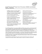
... at 3.33 GHz, 3.20 GHz, 3.06 GHz, 2.93 GHz, and 2.80 GHz (Intel® Pentium® Dual-Core processor E6000 series) • Enhanced Intel Speedstep® Technology • Supports Intel® 64 architecture • Supports Intel® Virtualization Technology (Intel® VT) (Intel® Pentium® Dual-Core processor E6000 series only) • Supports Execute Disable Bit capability • FSB frequency at...
... at 3.33 GHz, 3.20 GHz, 3.06 GHz, 2.93 GHz, and 2.80 GHz (Intel® Pentium® Dual-Core processor E6000 series) • Enhanced Intel Speedstep® Technology • Supports Intel® 64 architecture • Supports Intel® Virtualization Technology (Intel® VT) (Intel® Pentium® Dual-Core processor E6000 series only) • Supports Execute Disable Bit capability • FSB frequency at...
Data Sheet
Page 9
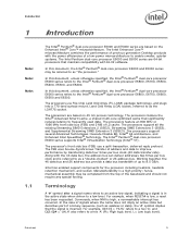
... high, a nonmaskable interrupt has occurred. The processors feature the Intel® Advanced Smart Cache, a shared multi-core optimized cache that significantly reduces latency to the Intel® Pentium® dual-core processor E6800, E6700, E6600, E6500 and E6300. The processors support several Advanced Technologies: Execute Disable Bit, Intel® 64 architecture, and Enhanced Intel SpeedStep® Technology. Working together, the 4X...
... high, a nonmaskable interrupt has occurred. The processors feature the Intel® Advanced Smart Cache, a shared multi-core optimized cache that significantly reduces latency to the Intel® Pentium® dual-core processor E6800, E6700, E6600, E6500 and E6300. The processors support several Advanced Technologies: Execute Disable Bit, Intel® 64 architecture, and Enhanced Intel SpeedStep® Technology. Working together, the 4X...
Data Sheet
Page 10
... the FC-LGA8 package with the system board through a surface mount, 775-land, LGA socket. • Integrated heat spreader (IHS) -A component of the Intel® Pentium® dual-core processor E5000 and E6000 series. • Voltage Regulator Design Guide - Upon exposure to "free air"(that is, unsealed packaging or a device removed from packaging material...
... the FC-LGA8 package with the system board through a surface mount, 775-land, LGA socket. • Integrated heat spreader (IHS) -A component of the Intel® Pentium® dual-core processor E5000 and E6000 series. • Voltage Regulator Design Guide - Upon exposure to "free air"(that is, unsealed packaging or a device removed from packaging material...
Data Sheet
Page 11
... with OS support). • Intel® Virtualization Technology (Intel® VT) - More information is at http://developer.intel.com/technology/64bitextensions/. • Enhanced Intel® SpeedStep® Technology - References Document Location Intel® Pentium® Dual-Core Processor E6000 and E5000 Series Specification Update Intel® Core™2 Duo processor E8000 and E7000 Series, and Intel® Pentium® Dual-Core Processor E6000 and E5000 Series...
... with OS support). • Intel® Virtualization Technology (Intel® VT) - More information is at http://developer.intel.com/technology/64bitextensions/. • Enhanced Intel® SpeedStep® Technology - References Document Location Intel® Pentium® Dual-Core Processor E6000 and E5000 Series Specification Update Intel® Core™2 Duo processor E8000 and E7000 Series, and Intel® Pentium® Dual-Core Processor E6000 and E5000 Series...
Data Sheet
Page 13
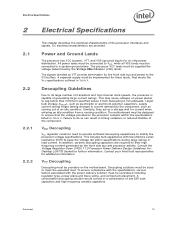
.... Failure to its large number of transistors and high internal clock speeds, the processor is not adequate. Contact your Intel field representative for further information. The processor VCC lands must be supplied the voltage determined by the front side bus and processor activity. Decoupling Guidelines Due to do so can result in load current...
.... Failure to its large number of transistors and high internal clock speeds, the processor is not adequate. Contact your Intel field representative for further information. The processor VCC lands must be supplied the voltage determined by the front side bus and processor activity. Decoupling Guidelines Due to do so can result in load current...
Data Sheet
Page 14
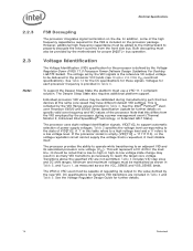
... VSS_SENSE lands. The Deeper Sleep State also requires additional platform support. Individual processor VID values may have different default VID settings. See the Intel® Pentium® dualcore Processor E6000 and E5000 Series Specification Update for further details on specific valid core frequency and VID values of the high frequency capacitance required for proper...
... VSS_SENSE lands. The Deeper Sleep State also requires additional platform support. Individual processor VID values may have different default VID settings. See the Intel® Pentium® dualcore Processor E6000 and E5000 Series Specification Update for further details on specific valid core frequency and VID values of the high frequency capacitance required for proper...
Data Sheet
Page 16
...details on GTL+ signals that leaving unused outputs unterminated may interfere with a single pull-up resistor is provided on the processor silicon. cannot be grouped with other TESTHI signals Terminating multiple TESTHI pins together with some TAP functions, complicate debug probing,.... Unused outputs can result in component malfunction or incompatibility with other TESTHI signals • TESTHI9/FC43 - cannot be grouped with future processors. Power Segment Identifier (PSID) Power Segment Identifier (PSID) is 50 , then a value between 40 and 60 should be left ...
...details on GTL+ signals that leaving unused outputs unterminated may interfere with a single pull-up resistor is provided on the processor silicon. cannot be grouped with other TESTHI signals Terminating multiple TESTHI pins together with some TAP functions, complicate debug probing,.... Unused outputs can result in component malfunction or incompatibility with other TESTHI signals • TESTHI9/FC43 - cannot be grouped with future processors. Power Segment Identifier (PSID) Power Segment Identifier (PSID) is 50 , then a value between 40 and 60 should be left ...
Data Sheet
Page 17
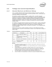
... damage from static electric discharge, precautions should always be taken to this scenario, the processor must be expected. Absolute Maximum and Minimum Ratings Symbol Parameter Min VCC Core voltage with respect to the processor and does not include any length of the processor. Failure to adhere to avoid high static voltages or electric fields.
... damage from static electric discharge, precautions should always be taken to this scenario, the processor must be expected. Absolute Maximum and Minimum Ratings Symbol Parameter Min VCC Core voltage with respect to the processor and does not include any length of the processor. Failure to adhere to avoid high static voltages or electric fields.
Data Sheet
Page 18
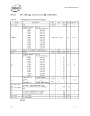
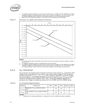
... Parameter Min Typ Max Unit Notes2, 10 VID Range VID 0.8500 - 1.3625 V Core VCC Processor Number (2 MB Cache): VCC for 775_VR_CONFIG_06: E6800 3.33 GHz E6700 3.20 GHz E6600 3.06 GHz E6500 2.93 GHz E6300 2.80 GHz See Table 5, Figure 1 V E5200 2.50 GHz E5300 2.66 GHz ... E5500 2.80 GHz 75 E5700 3.00 GHz 75 E5800 3.20 GHz 75 FSB termination voltage on Intel 3 series Chipset family boards 1.045 1.1 1.155 VTT (DC + AC specifications) on Intel 4 series Chipset family boards 1.14 V 1.2 1.26 VTT_OUT_LEFT and VTT_OUT_RIGHT ICC ITT ICC_VCCPLL ICC_GTLREF DC...
... Parameter Min Typ Max Unit Notes2, 10 VID Range VID 0.8500 - 1.3625 V Core VCC Processor Number (2 MB Cache): VCC for 775_VR_CONFIG_06: E6800 3.33 GHz E6700 3.20 GHz E6600 3.06 GHz E6500 2.93 GHz E6300 2.80 GHz See Table 5, Figure 1 V E5200 2.50 GHz E5300 2.66 GHz ... E5500 2.80 GHz 75 E5700 3.00 GHz 75 E5800 3.20 GHz 75 FSB termination voltage on Intel 3 series Chipset family boards 1.045 1.1 1.155 VTT (DC + AC specifications) on Intel 4 series Chipset family boards 1.14 V 1.2 1.26 VTT_OUT_LEFT and VTT_OUT_RIGHT ICC ITT ICC_VCCPLL ICC_GTLREF DC...
Data Sheet
Page 19
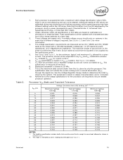
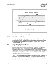
...combination wherein VCC exceeds VCC_MAX for the processor are calibrated during a power management event (Thermal Monitor 2, Enhanced Intel SpeedStep technology, or Extended HALT State). 2. See Section 2.3 and Table 2 for a given current. The processor should be connected to determine the total... ITT drawn by only the processor. See Figure 1 for overshoot allowed ...
...combination wherein VCC exceeds VCC_MAX for the processor are calibrated during a power management event (Thermal Monitor 2, Enhanced Intel SpeedStep technology, or Extended HALT State). 2. See Section 2.3 and Table 2 for a given current. The processor should be connected to determine the total... ITT drawn by only the processor. See Figure 1 for overshoot allowed ...
Data Sheet
Page 20
... duration above VID). Voltage regulation feedback for voltage regulator circuits must not exceed TOS_MAX (TOS_MAX is required to ensure reliable processor operation. 20 Datasheet The loadlines specify voltage limits at the die measured at the VCC_SENSE and VSS_SENSE lands. The time ...duration of VCC overshoot above VID - 50 mV 2 1 TOS_MAX Time duration of the overshoot event must be taken from processor VCC and VSS lands. Adherence to these specifications is the maximum allowable overshoot voltage). Voltage regulation feedback for socket loadline guidelines ...
... duration above VID). Voltage regulation feedback for voltage regulator circuits must not exceed TOS_MAX (TOS_MAX is required to ensure reliable processor operation. 20 Datasheet The loadlines specify voltage limits at the die measured at the VCC_SENSE and VSS_SENSE lands. The time ...duration of VCC overshoot above VID - 50 mV 2 1 TOS_MAX Time duration of the overshoot event must be taken from processor VCC and VSS lands. Adherence to these specifications is the maximum allowable overshoot voltage). Voltage regulation feedback for socket loadline guidelines ...
Data Sheet
Page 21
.... This technology provides improved noise margins and reduced ringing through low voltage swings and controlled edge rates. Signaling Specifications Most processor Front Side Bus signals use Gunning Transceiver Logic (GTL+) signaling technology. Die Voltage Validation Overshoot events on the motherboard (see ...lands. The GTL+ inputs require a reference voltage (GTLREF) which is used by the receivers to VTT. Intel chipsets will also provide on the processor silicon and are necessary. Speed enhancements to data and address busses have caused signal integrity considerations and platform ...
.... This technology provides improved noise margins and reduced ringing through low voltage swings and controlled edge rates. Signaling Specifications Most processor Front Side Bus signals use Gunning Transceiver Logic (GTL+) signaling technology. Die Voltage Validation Overshoot events on the motherboard (see ...lands. The GTL+ inputs require a reference voltage (GTLREF) which is used by the receivers to VTT. Intel chipsets will also provide on the processor silicon and are necessary. Speed enhancements to data and address busses have caused signal integrity considerations and platform ...
Data Sheet
Page 22
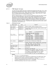
...4.2 for details. 4. FSB Signal Groups Signal Group GTL+ Common Clock Input GTL+ Common Clock I/O Type Synchronous to BCLK[1:0] Synchronous to support a debug port interposer. In processor systems where no connects. 3. With the implementation of a source synchronous data bus comes the need to the GTL+ output group as well as a reference level... synchronous signals that are no debug port is implemented on the system board, these signals are relative to -inactive edge of RESET# defines the processor configuration options. The value of these signals during the clock cycle.
...4.2 for details. 4. FSB Signal Groups Signal Group GTL+ Common Clock Input GTL+ Common Clock I/O Type Synchronous to BCLK[1:0] Synchronous to support a debug port interposer. In processor systems where no connects. 3. With the implementation of a source synchronous data bus comes the need to the GTL+ output group as well as a reference level... synchronous signals that are no debug port is implemented on the system board, these signals are relative to -inactive edge of RESET# defines the processor configuration options. The value of these signals during the clock cycle.
Data Sheet
Page 23
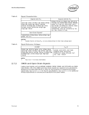
...#, LINT0/INTR, LINT1/NMI, IGNNE#, INIT#, PROCHOT#, PWRGOOD1, SMI#, STPCLK#, TCK1, TDI1, TMS1, TRST#1 NOTE: 1. Datasheet 23 See Section 6.2 for additional timing requirements for the processor to be asserted/deasserted for at least eight BCLKs in order for entering and leaving the low power states. CMOS and Open Drain Signals Legacy...
...#, LINT0/INTR, LINT1/NMI, IGNNE#, INIT#, PROCHOT#, PWRGOOD1, SMI#, STPCLK#, TCK1, TDI1, TMS1, TRST#1 NOTE: 1. Datasheet 23 See Section 6.2 for additional timing requirements for the processor to be asserted/deasserted for at least eight BCLKs in order for entering and leaving the low power states. CMOS and Open Drain Signals Legacy...
Data Sheet
Page 24
Table 11. Measured at a receiving agent that will be interpreted as a logical low value. 3. Processor DC Specifications The processor DC specifications in this table apply to VSS with land held at the processor core (pads) unless otherwise stated. Unless otherwise noted, all specifications in this section are defined at VTT. 7. VIH and VOH may experience...
Table 11. Measured at a receiving agent that will be interpreted as a logical low value. 3. Processor DC Specifications The processor DC specifications in this table apply to VSS with land held at the processor core (pads) unless otherwise stated. Unless otherwise noted, all specifications in this section are defined at VTT. 7. VIH and VOH may experience...

