
Smart Response Technology User Guide
Page 1
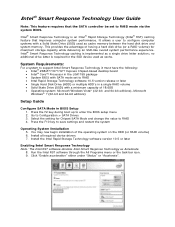
... Storage Technology software 10.5 version release or later • Single Hard Disk Drive (HDD) or multiple HDD's in BIOS Setup 1. Click "Enable acceleration" either under "Status" or "Accelerate". Intel® Smart Response Technology caching is implemented as Accelerate 8. You may now begin installation of 18.6GB • Operating system: Microsoft Windows Vista...
... Storage Technology software 10.5 version release or later • Single Hard Disk Drive (HDD) or multiple HDD's in BIOS Setup 1. Click "Enable acceleration" either under "Status" or "Accelerate". Intel® Smart Response Technology caching is implemented as Accelerate 8. You may now begin installation of 18.6GB • Operating system: Microsoft Windows Vista...
Technical Product Specification
Page 2
... specifications and product descriptions at any time, without further evaluation by estoppel or otherwise, to only the standard Intel® Desktop Board DZ77GA-70K with BIOS identifier GAZ7711H.86A. Intel, 3rd generation Intel Core processor family, and 2nd generation Intel Core processor family are available on the absence or characteristics of any such patents, trademarks, copyrights, or...
... specifications and product descriptions at any time, without further evaluation by estoppel or otherwise, to only the standard Intel® Desktop Board DZ77GA-70K with BIOS identifier GAZ7711H.86A. Intel, 3rd generation Intel Core processor family, and 2nd generation Intel Core processor family are available on the absence or characteristics of any such patents, trademarks, copyrights, or...
Technical Product Specification
Page 3
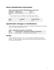
... errata, if any, are documented in a separate Specification Update. Board Identification Information Basic Desktop Board DZ77GA-70K Identification Information AA Revision BIOS Revision Notes G39009-400 GAZ7711H.86A.0021 1,2 Notes: 1. Specification Changes or Clarifications Date Type of Change... indicates the Specification Changes or Specification Clarifications that apply to the Intel® Desktop Board DZ77GA-70K. The AA number is found on a small label on page 56. See http://developer.intel.com/products/desktop/motherboard/index.htm for the latest documentation. iii...
... errata, if any, are documented in a separate Specification Update. Board Identification Information Basic Desktop Board DZ77GA-70K Identification Information AA Revision BIOS Revision Notes G39009-400 GAZ7711H.86A.0021 1,2 Notes: 1. Specification Changes or Clarifications Date Type of Change... indicates the Specification Changes or Specification Clarifications that apply to the Intel® Desktop Board DZ77GA-70K. The AA number is found on a small label on page 56. See http://developer.intel.com/products/desktop/motherboard/index.htm for the latest documentation. iii...

Technical Product Specification
Page 5
... type. It is intended to provide detailed, technical information about the conventions used on the Intel Desktop Board DZ77GA-70K A map of the resources of the Intel Desktop Board The features supported by the BIOS Setup program A description of the BIOS error messages, beep codes, and POST codes Regulatory compliance and battery disposal information Typographical Conventions...
... type. It is intended to provide detailed, technical information about the conventions used on the Intel Desktop Board DZ77GA-70K A map of the resources of the Intel Desktop Board The features supported by the BIOS Setup program A description of the BIOS error messages, beep codes, and POST codes Regulatory compliance and battery disposal information Typographical Conventions...

Technical Product Specification
Page 8
Intel Desktop Board DZ77GA-70K Technical Product Specification 1.11.3 Chassis Intrusion and Detection 36 1.11.4 Thermal Monitoring 37 1.12 Power Management 38 1.12.1 ACPI 38 1.... 68 2.7 Reliability 70 2.8 Environmental 70 3 Overview of BIOS Features 3.1 Introduction 71 3.2 BIOS Flash Memory Organization 72 3.3 Resource Configuration 72 3.3.1 PCI Autoconfiguration 72 3.4 System Management BIOS (SMBIOS 73 3.5 Legacy USB Support 73 3.6 BIOS Updates 74 3.6.1 Language Support 74 3.6.2 Custom Splash Screen 75 3.7 BIOS Recovery 75 3.8 Boot Options 76 3.8.1 Optical Drive Boot ...
Intel Desktop Board DZ77GA-70K Technical Product Specification 1.11.3 Chassis Intrusion and Detection 36 1.11.4 Thermal Monitoring 37 1.12 Power Management 38 1.12.1 ACPI 38 1.... 68 2.7 Reliability 70 2.8 Environmental 70 3 Overview of BIOS Features 3.1 Introduction 71 3.2 BIOS Flash Memory Organization 72 3.3 Resource Configuration 72 3.3.1 PCI Autoconfiguration 72 3.4 System Management BIOS (SMBIOS 73 3.5 Legacy USB Support 73 3.6 BIOS Updates 74 3.6.1 Language Support 74 3.6.2 Custom Splash Screen 75 3.7 BIOS Recovery 75 3.8 Boot Options 76 3.8.1 Optical Drive Boot ...

Technical Product Specification
Page 9
Back Panel Connectors 52 14. Board Dimensions 65 19. Contents 3.10 BIOS Security Features 78 3.11 Back to BIOS Button 79 3.12 BIOS Performance Features 79 4 Error Messages and Beep Codes 4.1 Speaker 81 4.2 BIOS Beep Codes 81 4.3 Front-panel Power LED Blink Codes 82 4.4 BIOS Error Messages 82 4.5 Port 80h Power On Self Test (POST) Codes...
Back Panel Connectors 52 14. Board Dimensions 65 19. Contents 3.10 BIOS Security Features 78 3.11 Back to BIOS Button 79 3.12 BIOS Performance Features 79 4 Error Messages and Beep Codes 4.1 Speaker 81 4.2 BIOS Beep Codes 81 4.3 Front-panel Power LED Blink Codes 82 4.4 BIOS Error Messages 82 4.5 Port 80h Power On Self Test (POST) Codes...
Technical Product Specification
Page 10
... Rear Chassis, and Auxiliary (4-Pin) Fan Headers ..... 57 23. Alternate Power LED Header 58 26. BIOS Setup Program Function Keys 72 38. Supervisor and User Password Functions 78 41. BIOS Error Messages 82 44. Intel Desktop Board DZ77GA-70K Technical Product Specification Tables 1. Feature Summary 13 3. HDMI Port Status Conditions 26 6. Audio Jack Support 30...
... Rear Chassis, and Auxiliary (4-Pin) Fan Headers ..... 57 23. Alternate Power LED Header 58 26. BIOS Setup Program Function Keys 72 38. Supervisor and User Password Functions 78 41. BIOS Error Messages 82 44. Intel Desktop Board DZ77GA-70K Technical Product Specification Tables 1. Feature Summary 13 3. HDMI Port Status Conditions 26 6. Audio Jack Support 30...

Technical Product Specification
Page 14
...PC Technology LAN Support Expansion Capabilities • Separate module that provides both Bluetooth* and WiFi included with the desktop board • Intel® BIOS resident in the SPI Flash device • Support for Advanced Configuration and Power Interface (ACPI), Plug and Play, and SMBIOS •... • Fan speed control using voltage control (4-pin fan headers front, rear, and auxiliary) with selectable support in BIOS for 3-wire fans • Support for Platform Environmental Control Interface (PECI) 14 Intel Desktop Board DZ77GA-70K Technical Product Specification Table 2.
...PC Technology LAN Support Expansion Capabilities • Separate module that provides both Bluetooth* and WiFi included with the desktop board • Intel® BIOS resident in the SPI Flash device • Support for Advanced Configuration and Power Interface (ACPI), Plug and Play, and SMBIOS •... • Fan speed control using voltage control (4-pin fan headers front, rear, and auxiliary) with selectable support in BIOS for 3-wire fans • Support for Platform Environmental Control Interface (PECI) 14 Intel Desktop Board DZ77GA-70K Technical Product Specification Table 2.

Technical Product Specification
Page 16
...speaker V Main power connector (2 x 12) W Onboard power button X Onboard reset button Y Power Supervisor LED (Power Fault) Z Intel Z77 Express Chipset AA SATA 6.0 Gb/s connectors through the PCH (blue) BB SATA 3.0 Gb/s connectors through the PCH (black) CC...BIOS configuration jumper block continued 16 x16 compatible) D S/PDIF out header E Conventional PCI bus add-in card connector F PCI Express x1 bus add-in card connector G PCI Express x16 bus add-in card connector H Battery I PCI Express x1 bus add-in card connector (x8 electrical; Intel Desktop Board DZ77GA-70K...
...speaker V Main power connector (2 x 12) W Onboard power button X Onboard reset button Y Power Supervisor LED (Power Fault) Z Intel Z77 Express Chipset AA SATA 6.0 Gb/s connectors through the PCH (blue) BB SATA 3.0 Gb/s connectors through the PCH (black) CC...BIOS configuration jumper block continued 16 x16 compatible) D S/PDIF out header E Conventional PCI bus add-in card connector F PCI Express x1 bus add-in card connector G PCI Express x16 bus add-in card connector H Battery I PCI Express x1 bus add-in card connector (x8 electrical; Intel Desktop Board DZ77GA-70K...

Technical Product Specification
Page 19
... the future. Visit this World Wide Web site: Intel Desktop Board DZ77GA-70K http://www.intel.com/products/motherboard/index.htm Desktop Board Support http://www.intel.com/p/en_US/support?iid=hdr+support Available configurations for the Intel http://ark.intel.com Desktop Board DZ77GA-70K Supported processors Chipset information BIOS and driver updates Tested memory Integration information http://processormatch...
... the future. Visit this World Wide Web site: Intel Desktop Board DZ77GA-70K http://www.intel.com/products/motherboard/index.htm Desktop Board Support http://www.intel.com/p/en_US/support?iid=hdr+support Available configurations for the Intel http://ark.intel.com Desktop Board DZ77GA-70K Supported processors Chipset information BIOS and driver updates Tested memory Integration information http://processormatch...
Technical Product Specification
Page 21
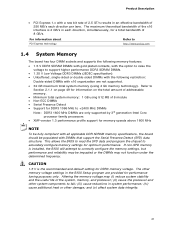
...single-sided or double-sided DIMMs with the following restriction: Double-sided DIMMs with x16 organization are only supported by 3rd generation Intel Core processor family processors • XMP version 1.3 performance profile support for memory speeds above 1600 MHz NOTE To be fully compliant... system performance; (iv) cause additional heat or other memory voltage settings in the BIOS Setup program are provided for optimum performance. The other damage; CAUTION 1.5 V is installed, the BIOS will attempt to correctly configure the memory settings, but performance and reliability may be ...
...single-sided or double-sided DIMMs with the following restriction: Double-sided DIMMs with x16 organization are only supported by 3rd generation Intel Core processor family processors • XMP version 1.3 performance profile support for memory speeds above 1600 MHz NOTE To be fully compliant... system performance; (iv) cause additional heat or other memory voltage settings in the BIOS Setup program are provided for optimum performance. The other damage; CAUTION 1.5 V is installed, the BIOS will attempt to correctly configure the memory settings, but performance and reliability may be ...
Technical Product Specification
Page 26
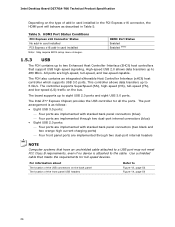
The PCH also contains an integrated eXtensible Host Controller Interface (xHCI) host controller which supports USB 3.0 ports. The Intel Z77 Express Chipset provides the USB controller for full-speed devices. All ports are implemented through two dual-port internal ... Note: May require BIOS setup menu changes. High-speed USB 2.0 allows data transfers up to 480 Mb/s. This controller allows data transfers up to 5 Gb/s. The board supports up to eight USB 2.0 ports and eight USB 3.0 ports. Intel Desktop Board DZ77GA-70K Technical Product Specification Depending...
The PCH also contains an integrated eXtensible Host Controller Interface (xHCI) host controller which supports USB 3.0 ports. The Intel Z77 Express Chipset provides the USB controller for full-speed devices. All ports are implemented through two dual-port internal ... Note: May require BIOS setup menu changes. High-speed USB 2.0 allows data transfers up to 480 Mb/s. This controller allows data transfers up to 5 Gb/s. The board supports up to eight USB 2.0 ports and eight USB 3.0 ports. Intel Desktop Board DZ77GA-70K Technical Product Specification Depending...
Technical Product Specification
Page 28
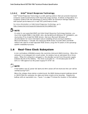
... powers the real-time clock and CMOS memory. When the voltage drops below a certain level, the BIOS Setup program settings stored in the BIOS. See your Microsoft Windows XP documentation for maximum storage capacity with an equivalent one. Replace the battery ... reset and the user will be accurate. For more information about installing drivers during POST. Intel Desktop Board DZ77GA-70K Technical Product Specification 1.5.4.2 Intel® Smart Response Technology Intel® Smart Response Technology is a disk caching solution that can provide improved computer system performance...
... powers the real-time clock and CMOS memory. When the voltage drops below a certain level, the BIOS Setup program settings stored in the BIOS. See your Microsoft Windows XP documentation for maximum storage capacity with an equivalent one. Replace the battery ... reset and the user will be accurate. For more information about installing drivers during POST. Intel Desktop Board DZ77GA-70K Technical Product Specification 1.5.4.2 Intel® Smart Response Technology Intel® Smart Response Technology is a disk caching solution that can provide improved computer system performance...
Technical Product Specification
Page 29
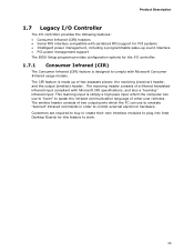
...with Microsoft CIR specifications, and also a "learning" infrared input. This learning input is made up event interface • PCI power management support The BIOS Setup program provides configuration options for the I /O controller provides the following features: • Consumer Infrared (CIR) headers • Serial IRQ interface compatible... commands in order to work. 29 Customers are required to buy or create their own interface modules to plug into Intel Desktop Boards for PCI systems • Intelligent power management, including a programmable wake-up of other user remotes.
...with Microsoft CIR specifications, and also a "learning" infrared input. This learning input is made up event interface • PCI power management support The BIOS Setup program provides configuration options for the I /O controller provides the following features: • Consumer Infrared (CIR) headers • Serial IRQ interface compatible... commands in order to work. 29 Customers are required to buy or create their own interface modules to plug into Intel Desktop Boards for PCI systems • Intelligent power management, including a programmable wake-up of other user remotes.
Technical Product Specification
Page 41
... and Instantly Available PC technology features are used. NOTE The use of the main power connector Refer to the power state it was in the BIOS Setup program's Boot menu. The computer's response can damage the power supply. Failure to do so can be set using the Last Power State feature...
... and Instantly Available PC technology features are used. NOTE The use of the main power connector Refer to the power state it was in the BIOS Setup program's Boot menu. The computer's response can damage the power supply. Failure to do so can be set using the Last Power State feature...

Technical Product Specification
Page 43
... from USB requires the use of Instantly Available PC technology requires operating system support and PCI 2.2 compliant add-in cards, PCI Express add-in the BIOS, the computer will appear to be capable of a USB peripheral that can damage the power supply. NOTE Wake from an ACPI S5 state. 43 Instantly... the RTC Date and Time is asserted, the computer wakes from an ACPI S3, S4, or S5 state (with Wake on PME enabled in the BIOS). 1.12.2.7 WAKE# Signal Wake-up device or event, the system quickly returns to wake the computer.
... from USB requires the use of Instantly Available PC technology requires operating system support and PCI 2.2 compliant add-in cards, PCI Express add-in the BIOS, the computer will appear to be capable of a USB peripheral that can damage the power supply. NOTE Wake from an ACPI S5 state. 43 Instantly... the RTC Date and Time is asserted, the computer wakes from an ACPI S3, S4, or S5 state (with Wake on PME enabled in the BIOS). 1.12.2.7 WAKE# Signal Wake-up device or event, the system quickly returns to wake the computer.
Technical Product Specification
Page 44
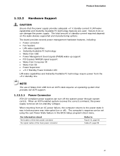
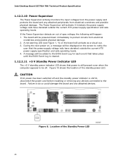
... board will be powered down immediately to the board. Figure 8. Figure 10 shows the location of the Standby Power LED 44 Intel Desktop Board DZ77GA-70K Technical Product Specification 1.12.2.10 Power Supervisor The Power Supervisor actively monitors the input voltages from the power supply and protects the board...switched off . During the next power on, a message will be displayed on the board will be added to the BIOS Event Log for each event that takes place until the BIOS Event Log is cleared. 1.12.2.11 +5 V Standby Power Indicator LED The +5 V standby power indicator LED shows ...
... board will be powered down immediately to the board. Figure 8. Figure 10 shows the location of the Standby Power LED 44 Intel Desktop Board DZ77GA-70K Technical Product Specification 1.12.2.10 Power Supervisor The Power Supervisor actively monitors the input voltages from the power supply and protects the board...switched off . During the next power on, a message will be displayed on the board will be added to the BIOS Event Log for each event that takes place until the BIOS Event Log is cleared. 1.12.2.11 +5 V Standby Power Indicator LED The +5 V standby power indicator LED shows ...

Technical Product Specification
Page 46
Location of Board Status LEDs Table 11 gives a description of the board status LEDs. Intel Desktop Board DZ77GA-70K Technical Product Specification 1.13 Board Status LEDs The Desktop Board provides 11 LEDs that allow you to monitor the board's progress through the BIOS Power-on . Figure 10. Figure 10 shows the location of the LEDs shown in Figure 10. 46 When the BIOS starts an activity such as memory initialization, the corresponding LED starts flashing. Once the activity has completed, the LED will remain on Self-Test. At initial power on, all the LEDs are off.
Location of Board Status LEDs Table 11 gives a description of the board status LEDs. Intel Desktop Board DZ77GA-70K Technical Product Specification 1.13 Board Status LEDs The Desktop Board provides 11 LEDs that allow you to monitor the board's progress through the BIOS Power-on . Figure 10. Figure 10 shows the location of the LEDs shown in Figure 10. 46 When the BIOS starts an activity such as memory initialization, the corresponding LED starts flashing. Once the activity has completed, the LED will remain on Self-Test. At initial power on, all the LEDs are off.
Technical Product Specification
Page 47
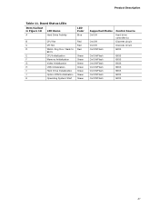
.../Callout in Figure 10 LED Name A Hard Drive Activity LED Color Blue B CPU Hot Red C VR Hot Red D Watch Dog Fire / Back to Red BIOS E CPU Initialization Green F Memory Initialization Green G Video Initialization Green H USB Initialization Green I Hard Drive Initialization Green J Option ROM Initialization Green K Operating System ...Start Green Supported Modes On/Off On/Off On/Off On/Off/Flash Control Source Hard drive controller(s) Discrete circuit Discrete circuit BIOS On/Off/Flash On/Off/Flash On/Off/Flash On/Off/Flash On/Off/Flash On/Off/Flash On/Off/Flash...
.../Callout in Figure 10 LED Name A Hard Drive Activity LED Color Blue B CPU Hot Red C VR Hot Red D Watch Dog Fire / Back to Red BIOS E CPU Initialization Green F Memory Initialization Green G Video Initialization Green H USB Initialization Green I Hard Drive Initialization Green J Option ROM Initialization Green K Operating System ...Start Green Supported Modes On/Off On/Off On/Off On/Off/Flash Control Source Hard drive controller(s) Discrete circuit Discrete circuit BIOS On/Off/Flash On/Off/Flash On/Off/Flash On/Off/Flash On/Off/Flash On/Off/Flash On/Off/Flash...
Technical Product Specification
Page 49
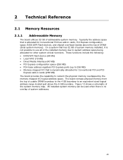
...of the installed memory due to system address space being allocated for Conventional PCI and PCI Express add-in cards, PCI Express configuration space, BIOS (SPI Flash device), and chipset overhead resides above the 4 GB boundary. Figure 12 shows a schematic of usable DRAM boundary to the ...4 GB boundary to 256 MB) • Memory-mapped I /O logical address space. These functions include the following: • BIOS/SPI Flash device (64 Mb) • Local APIC (19 MB) • Direct Media Interface (40 MB) • PCI Express configuration space (256 MB)...
...of the installed memory due to system address space being allocated for Conventional PCI and PCI Express add-in cards, PCI Express configuration space, BIOS (SPI Flash device), and chipset overhead resides above the 4 GB boundary. Figure 12 shows a schematic of usable DRAM boundary to the ...4 GB boundary to 256 MB) • Memory-mapped I /O logical address space. These functions include the following: • BIOS/SPI Flash device (64 Mb) • Local APIC (19 MB) • Direct Media Interface (40 MB) • PCI Express configuration space (256 MB)...


