
Smart Response Technology User Guide
Page 1
...Solid State Drive (SSD) with a Solid State Drive (SSD) used as cache memory between the hard disk drive and system memory. System Requirements: For a system to support Intel Smart Response Technology it must have the following: • Intel® Z68/Z77/H77/Q77 Express Chipset-based desktop board •...; Intel® Core™ Processor in the LGA1155 package • ...
...Solid State Drive (SSD) with a Solid State Drive (SSD) used as cache memory between the hard disk drive and system memory. System Requirements: For a system to support Intel Smart Response Technology it must have the following: • Intel® Z68/Z77/H77/Q77 Express Chipset-based desktop board •...; Intel® Core™ Processor in the LGA1155 package • ...
Smart Response Technology User Guide
Page 2
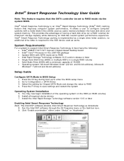
10. Select the size from the SSD to accelerate the system volume or system disk for the cache memory. It is now successfully configured with the Intel Smart Response Technology! * Other names, brands, and logos may be claimed as a cache device. 11. By default, Enhanced mode is... automatically created. 12. Your system is highly recommended to be allocated for maximum performance. 13. Intel, the Intel logo, Intel Core, and Core Inside are trademarks of others. All rights reserved. Select the acceleration mode, and then click "OK". Maximized mode: ...
10. Select the size from the SSD to accelerate the system volume or system disk for the cache memory. It is now successfully configured with the Intel Smart Response Technology! * Other names, brands, and logos may be claimed as a cache device. 11. By default, Enhanced mode is... automatically created. 12. Your system is highly recommended to be allocated for maximum performance. 13. Intel, the Intel logo, Intel Core, and Core Inside are trademarks of others. All rights reserved. Select the acceleration mode, and then click "OK". Maximized mode: ...

Technical Product Specification
Page 7
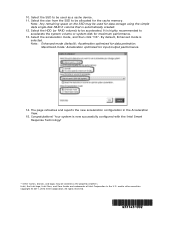
... Conventions v 1 Product Description 1.1 Overview 13 1.1.1 Feature Summary 13 1.1.2 Board Layout 15 1.1.3 Block Diagram 18 1.2 Online Support 19 1.3 Processor 19 1.3.1 Graphics Subsystem 20 1.4 System Memory 21 1.4.1 Memory Configurations 23 1.5 Intel® Z77 Express Chipset 25 1.5.1 Direct Media Interface (DMI 25 1.5.2 Display Interfaces 25 1.5.3 USB 26 1.5.4 SATA Interfaces 27 1.6 Real-Time Clock Subsystem 28 1.7 Legacy...
... Conventions v 1 Product Description 1.1 Overview 13 1.1.1 Feature Summary 13 1.1.2 Board Layout 15 1.1.3 Block Diagram 18 1.2 Online Support 19 1.3 Processor 19 1.3.1 Graphics Subsystem 20 1.4 System Memory 21 1.4.1 Memory Configurations 23 1.5 Intel® Z77 Express Chipset 25 1.5.1 Direct Media Interface (DMI 25 1.5.2 Display Interfaces 25 1.5.3 USB 26 1.5.4 SATA Interfaces 27 1.6 Real-Time Clock Subsystem 28 1.7 Legacy...

Technical Product Specification
Page 8
Intel Desktop Board DZ77GA-70K Technical Product Specification 1.11.3 Chassis Intrusion and Detection 36 1.11.4 Thermal Monitoring 37 1.12 Power Management 38 1.12.1 ACPI 38 1.12.2 Hardware Support 41 1.13 Board Status LEDs 46 1.14 Onboard Power and Reset Buttons 48 2 Technical Reference 2.1 Memory Resources 49 2.1.1 Addressable Memory 49 2.1.2 Memory...68 2.7 Reliability 70 2.8 Environmental 70 3 Overview of BIOS Features 3.1 Introduction 71 3.2 BIOS Flash Memory Organization 72 3.3 Resource Configuration 72 3.3.1 PCI Autoconfiguration 72 3.4 System Management BIOS (SMBIOS 73 3.5...
Intel Desktop Board DZ77GA-70K Technical Product Specification 1.11.3 Chassis Intrusion and Detection 36 1.11.4 Thermal Monitoring 37 1.12 Power Management 38 1.12.1 ACPI 38 1.12.2 Hardware Support 41 1.13 Board Status LEDs 46 1.14 Onboard Power and Reset Buttons 48 2 Technical Reference 2.1 Memory Resources 49 2.1.1 Addressable Memory 49 2.1.2 Memory...68 2.7 Reliability 70 2.8 Environmental 70 3 Overview of BIOS Features 3.1 Introduction 71 3.2 BIOS Flash Memory Organization 72 3.3 Resource Configuration 72 3.3.1 PCI Autoconfiguration 72 3.4 System Management BIOS (SMBIOS 73 3.5...

Technical Product Specification
Page 9
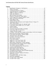
... Compliance and Battery Disposal Information 5.1 Regulatory Compliance 89 5.1.1 Safety Standards 89 5.1.2 European Union Declaration of the Onboard Power and Reset Buttons 48 12. Detailed System Memory Address Map 50 13. Connection Diagram for Front Panel USB 2.0 Headers 62 17. Connection Diagram for Front Panel Header 60 16.
... Compliance and Battery Disposal Information 5.1 Regulatory Compliance 89 5.1.1 Safety Standards 89 5.1.2 European Union Declaration of the Onboard Power and Reset Buttons 48 12. Detailed System Memory Address Map 50 13. Connection Diagram for Front Panel USB 2.0 Headers 62 17. Connection Diagram for Front Panel Header 60 16.
Technical Product Specification
Page 10
...for BIOS Recovery 75 39. Front Panel USB 3.0 Connectors 56 21. Alternate Power LED Header 58 26. Thermal Considerations for Intel HD Audio 55 16. BIOS Setup Program Function Keys 72 38. Wake-up Devices and Events 40 11. Environmental Specifications 70...Header 55 15. States for a Two-Color Power LED 61 31. Supported Memory Configurations 22 5. Front Panel Header 60 29. Audio Jack Support 30 7. Specification Changes or Clarifications iii 2. Intel Desktop Board DZ77GA-70K Technical Product Specification Tables 1. Feature Summary 13 3. HDMI Port Status Conditions ...
...for BIOS Recovery 75 39. Front Panel USB 3.0 Connectors 56 21. Alternate Power LED Header 58 26. Thermal Considerations for Intel HD Audio 55 16. BIOS Setup Program Function Keys 72 38. Wake-up Devices and Events 40 11. Environmental Specifications 70...Header 55 15. States for a Two-Color Power LED 61 31. Supported Memory Configurations 22 5. Front Panel Header 60 29. Audio Jack Support 30 7. Specification Changes or Clarifications iii 2. Intel Desktop Board DZ77GA-70K Technical Product Specification Tables 1. Feature Summary 13 3. HDMI Port Status Conditions ...

Technical Product Specification
Page 13
... four DIMMs using 4 Gb memory technology • Support for non-ECC memory • Support for 1.5 V (standard voltage) and 1.35 V (low voltage) JEDEC memory • Support for XMP memory Note: DDR3 1600 MHz DIMMs are only supported by 3rd generation Intel Core processor family processors Legacy ...PCI Express 3.0 x16 add-in x8 mode when both slots are populated) ― Integrated memory controller with dual channel DDR3 memory support ― Integrated graphics processing (processors with Intel® HD Graphics) ― External graphics interface controller • Four 240-pin DDR3 ...
... four DIMMs using 4 Gb memory technology • Support for non-ECC memory • Support for 1.5 V (standard voltage) and 1.35 V (low voltage) JEDEC memory • Support for XMP memory Note: DDR3 1600 MHz DIMMs are only supported by 3rd generation Intel Core processor family processors Legacy ...PCI Express 3.0 x16 add-in x8 mode when both slots are populated) ― Integrated memory controller with dual channel DDR3 memory support ― Integrated graphics processing (processors with Intel® HD Graphics) ― External graphics interface controller • Four 240-pin DDR3 ...

Technical Product Specification
Page 19
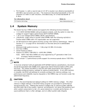
... 95 W. For information about ... See the Intel web site listed below for the Intel http://ark.intel.com Desktop Board DZ77GA-70K Supported processors Chipset information BIOS and driver updates Tested memory Integration information http://processormatch.intel.com http://www.intel.com/products/desktop/chipsets/index.htm http://downloadcenter.intel.com http://www.intel.com/support/motherboards/desktop/sb/CS025414...
... 95 W. For information about ... See the Intel web site listed below for the Intel http://ark.intel.com Desktop Board DZ77GA-70K Supported processors Chipset information BIOS and driver updates Tested memory Integration information http://processormatch.intel.com http://www.intel.com/products/desktop/chipsets/index.htm http://downloadcenter.intel.com http://www.intel.com/support/motherboards/desktop/sb/CS025414...

Technical Product Specification
Page 20
Intel Desktop Board DZ77GA-70K Technical Product Specification 1.3.1 Graphics Subsystem The board supports graphics through either the processor Intel HD Graphics or a PCI Express x16 add-in graphics card. 1.3.1.1 Processor Graphics The board supports integrated graphics through the Intel® Flexible Display Interface (Intel...HDMI 1.4a Dynamic Video Memory Technology (DVMT) 5.0 support Support of up to 1.7 GB Video Memory with 4 GB and above system memory configuration 1.3.1.2 PCI Express x16 Graphics 3rd generation Intel Core processor family processors support PCI ...
Intel Desktop Board DZ77GA-70K Technical Product Specification 1.3.1 Graphics Subsystem The board supports graphics through either the processor Intel HD Graphics or a PCI Express x16 add-in graphics card. 1.3.1.1 Processor Graphics The board supports integrated graphics through the Intel® Flexible Display Interface (Intel...HDMI 1.4a Dynamic Video Memory Technology (DVMT) 5.0 support Support of up to 1.7 GB Video Memory with 4 GB and above system memory configuration 1.3.1.2 PCI Express x16 Graphics 3rd generation Intel Core processor family processors support PCI ...
Technical Product Specification
Page 21
...) cause reductions in the BIOS Setup program are only supported by 3rd generation Intel Core processor family processors • XMP version 1.3 performance profile support for performance tuning purposes only. and (v) affect system data integrity. 21 If non-SPD memory is installed, the BIOS will attempt to +2400 MHz DIMMs Note: DDR3 1600...
...) cause reductions in the BIOS Setup program are only supported by 3rd generation Intel Core processor family processors • XMP version 1.3 performance profile support for performance tuning purposes only. and (v) affect system data integrity. 21 If non-SPD memory is installed, the BIOS will attempt to +2400 MHz DIMMs Note: DDR3 1600...

Technical Product Specification
Page 22
... 22 For information on the desktop board, if used with the memory manufacturer for any particular purpose. Table 4 lists the supported DIMM configurations. Intel Desktop Board DZ77GA-70K Technical Product Specification Intel has not tested and does not warranty the operation of SDRAM). Supported Memory Configurations DIMM Capacity SDRAM Configuration (Note) Density SDRAM Organization Front-side...
... 22 For information on the desktop board, if used with the memory manufacturer for any particular purpose. Table 4 lists the supported DIMM configurations. Intel Desktop Board DZ77GA-70K Technical Product Specification Intel has not tested and does not warranty the operation of SDRAM). Supported Memory Configurations DIMM Capacity SDRAM Configuration (Note) Density SDRAM Organization Front-side...

Technical Product Specification
Page 23
...world applications. This mode is used . If different speed DIMMs are used between channels, the slowest memory timing will be used between channels, the slowest memory timing will be equal. If different speed DIMMs are used . • Single channel (Asymmetric) mode.... This mode offers the highest throughput for real world applications. Product Description 1.4.1 Memory Configurations The 3rd generation Intel Core processor family and 2nd generation Intel Core processor family processors support the following types of both DIMM channels are unequal. This mode is...
...world applications. This mode is used . If different speed DIMMs are used between channels, the slowest memory timing will be used between channels, the slowest memory timing will be equal. If different speed DIMMs are used . • Single channel (Asymmetric) mode.... This mode offers the highest throughput for real world applications. Product Description 1.4.1 Memory Configurations The 3rd generation Intel Core processor family and 2nd generation Intel Core processor family processors support the following types of both DIMM channels are unequal. This mode is...

Technical Product Specification
Page 24
DIMM Configuration NOTE For best memory performance always install memory in the blue DIMM sockets if installing only two DIMMs on your board. 24 Figure 3. Intel Desktop Board DZ77GA-70K Technical Product Specification Figure 3 illustrates the DIMM configuration.
DIMM Configuration NOTE For best memory performance always install memory in the blue DIMM sockets if installing only two DIMMs on your board. 24 Figure 3. Intel Desktop Board DZ77GA-70K Technical Product Specification Figure 3 illustrates the DIMM configuration.

Technical Product Specification
Page 25
... between the processor and PCH. The processor houses the memory interface, display planes, and pipes while the PCH has transcoder and display interface or ports. The Intel Z77 Express Chipset is 1920 x 1200 (WUXGA). For information about The Intel Z77 Express Chipset Resources used by the chipset Refer to... -chip connection between the processor and the PCH. The display data from the frame buffer is the chip-to http://www.intel.com/products/desktop/chipsets/index.htm Chapter 2 1.5.1 Direct Media Interface (DMI) DMI is processed in the processor with all ATSC and ...
... between the processor and PCH. The processor houses the memory interface, display planes, and pipes while the PCH has transcoder and display interface or ports. The Intel Z77 Express Chipset is 1920 x 1200 (WUXGA). For information about The Intel Z77 Express Chipset Resources used by the chipset Refer to... -chip connection between the processor and the PCH. The display data from the frame buffer is the chip-to http://www.intel.com/products/desktop/chipsets/index.htm Chapter 2 1.5.1 Direct Media Interface (DMI) DMI is processed in the processor with all ATSC and ...
Technical Product Specification
Page 28
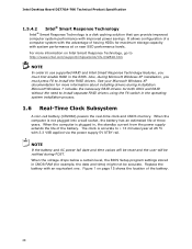
... A coin-cell battery (CR2032) powers the real-time clock and CMOS memory. Replace the battery with improved power savings. Figure 1 on Intel Smart Response Technology, go to http://www.intel.com/support/chipsets/sb/CS-032826.htm NOTE In order to install separate RAID...computer is a disk caching solution that can provide improved computer system performance with an equivalent one. Intel Desktop Board DZ77GA-70K Technical Product Specification 1.5.4.2 Intel® Smart Response Technology Intel® Smart Response Technology is not plugged into a wall socket, the battery has an estimated ...
... A coin-cell battery (CR2032) powers the real-time clock and CMOS memory. Replace the battery with improved power savings. Figure 1 on Intel Smart Response Technology, go to http://www.intel.com/support/chipsets/sb/CS-032826.htm NOTE In order to install separate RAID...computer is a disk caching solution that can provide improved computer system performance with an equivalent one. Intel Desktop Board DZ77GA-70K Technical Product Specification 1.5.4.2 Intel® Smart Response Technology Intel® Smart Response Technology is not plugged into a wall socket, the battery has an estimated ...

Technical Product Specification
Page 46
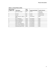
Intel Desktop Board DZ77GA-70K Technical Product Specification 1.13 Board Status LEDs The Desktop Board provides 11 LEDs that allow you to monitor the board's progress through the BIOS Power-on , all the LEDs are off. At initial power on Self-Test. Once the activity has completed, the LED will remain on. Figure 10 shows the location of the LEDs shown in Figure 10. 46 When the BIOS starts an activity such as memory initialization, the corresponding LED starts flashing. Location of Board Status LEDs Table 11 gives a description of the board status LEDs. Figure 10.
Intel Desktop Board DZ77GA-70K Technical Product Specification 1.13 Board Status LEDs The Desktop Board provides 11 LEDs that allow you to monitor the board's progress through the BIOS Power-on , all the LEDs are off. At initial power on Self-Test. Once the activity has completed, the LED will remain on. Figure 10 shows the location of the LEDs shown in Figure 10. 46 When the BIOS starts an activity such as memory initialization, the corresponding LED starts flashing. Location of Board Status LEDs Table 11 gives a description of the board status LEDs. Figure 10.
Technical Product Specification
Page 47
... 10 LED Name A Hard Drive Activity LED Color Blue B CPU Hot Red C VR Hot Red D Watch Dog Fire / Back to Red BIOS E CPU Initialization Green F Memory Initialization Green G Video Initialization Green H USB Initialization Green I Hard Drive Initialization Green J Option ROM Initialization Green K Operating System Start Green Supported Modes On/Off On...
... 10 LED Name A Hard Drive Activity LED Color Blue B CPU Hot Red C VR Hot Red D Watch Dog Fire / Back to Red BIOS E CPU Initialization Green F Memory Initialization Green G Video Initialization Green H USB Initialization Green I Hard Drive Initialization Green J Option ROM Initialization Green K Operating System Start Green Supported Modes On/Off On...
Technical Product Specification
Page 49
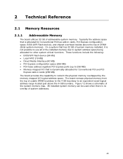
... chipset overhead resides above the 4 GB boundary. Figure 12 shows a schematic of addressable system memory. 2 Technical Reference 2.1 Memory Resources 2.1.1 Addressable Memory The board utilizes 32 GB of the system memory map. These functions include the following: • BIOS/SPI Flash device (64 Mb) •...Express configuration space (256 MB) • PCH base address registers PCI Express ports (up to reclaim the physical memory overlapped by the memory mapped I/O logical address space. On a system that is not possible to system address space being allocated for Conventional ...
... chipset overhead resides above the 4 GB boundary. Figure 12 shows a schematic of addressable system memory. 2 Technical Reference 2.1 Memory Resources 2.1.1 Addressable Memory The board utilizes 32 GB of the system memory map. These functions include the following: • BIOS/SPI Flash device (64 Mb) •...Express configuration space (256 MB) • PCH base address registers PCI Express ports (up to reclaim the physical memory overlapped by the memory mapped I/O logical address space. On a system that is not possible to system address space being allocated for Conventional ...

Technical Product Specification
Page 51
... headers are not overcurrent protected and should connect only to devices inside the computer's chassis, such as IEEE 1394a. Video memory and BIOS Extended BIOS data (movable by the external devices could cause damage to the computer's chassis. The connectors can ... K - 800 K 639 K - 640 K 512 K - 639 K 0 K - 512 K A0000 - A fault in the load presented by memory manager software) Extended conventional memory Conventional memory 2.2 Connectors and Headers CAUTION Only the following connectors and headers have overcurrent protection: back panel and front panel USB, as well as fans...
... headers are not overcurrent protected and should connect only to devices inside the computer's chassis, such as IEEE 1394a. Video memory and BIOS Extended BIOS data (movable by the external devices could cause damage to the computer's chassis. The connectors can ... K - 800 K 639 K - 640 K 512 K - 639 K 0 K - 512 K A0000 - A fault in the load presented by memory manager software) Extended conventional memory Conventional memory 2.2 Connectors and Headers CAUTION Only the following connectors and headers have overcurrent protection: back panel and front panel USB, as well as fans...

Technical Product Specification
Page 71
...revision code. The BIOS displays a message during POST identifying the type of BIOS Features 3.1 Introduction The board uses an Intel BIOS that is stored in the Serial Peripheral Interface Flash Memory (SPI Flash) and can be updated using a disk-based program. Maintenance Main Configuration Performance Security Power Boot Exit ... page 63 shows how to configure mode and the computer is accessed by pressing the key after the Power-On Self-Test (POST) memory test begins and before the operating system boot begins. When the BIOS Setup configuration jumper is set to put the board in the BIOS...
...revision code. The BIOS displays a message during POST identifying the type of BIOS Features 3.1 Introduction The board uses an Intel BIOS that is stored in the Serial Peripheral Interface Flash Memory (SPI Flash) and can be updated using a disk-based program. Maintenance Main Configuration Performance Security Power Boot Exit ... page 63 shows how to configure mode and the computer is accessed by pressing the key after the Power-On Self-Test (POST) memory test begins and before the operating system boot begins. When the BIOS Setup configuration jumper is set to put the board in the BIOS...


