Product Guide
Page 5
Contents 1 Desktop Board Features Supported Operating Systems 11 Desktop Board Components 12 Processor ...14 Main Memory...15 Intel® X38 Express Chipset 15 Audio Subsystem...Configuration 19 Security Passwords 19 Hardware Management 20 Hardware Monitoring and Fan Speed Control 20 Intel® Precision Cooling Technology 20 Chassis Intrusion 20 Power Management 21 Software Support 21 ACPI...26 Battery ...27 Real-Time Clock 27 2 Installing and Replacing Desktop Board Components Before You Begin 29 Installation Precautions 30 Prevent Power Supply Overload 30 Observe Safety ...
Contents 1 Desktop Board Features Supported Operating Systems 11 Desktop Board Components 12 Processor ...14 Main Memory...15 Intel® X38 Express Chipset 15 Audio Subsystem...Configuration 19 Security Passwords 19 Hardware Management 20 Hardware Monitoring and Fan Speed Control 20 Intel® Precision Cooling Technology 20 Chassis Intrusion 20 Power Management 21 Software Support 21 ACPI...26 Battery ...27 Real-Time Clock 27 2 Installing and Replacing Desktop Board Components Before You Begin 29 Installation Precautions 30 Prevent Power Supply Overload 30 Observe Safety ...
Product Guide
Page 7
LAN Connector LEDs 17 3. Installing the I/O Shield 31 7. Dual Channel Memory Configuration with Four DIMMs 41 19. Connecting the IDE Cable 48 26. Back Panel Audio Connectors 55 vii Remove the...EU RoHS 79 China RoHS 80 EMC Regulations 82 Ensure Electromagnetic Compatibility (EMC) Compliance 83 Product Certifications 84 Board-Level Certification Markings 84 Chassis and Component Certifications 85 Figures 1. Install the Processor 35 13. Desktop Board DX38BT Mounting Screw Hole Locations 32 8. Close the Load Plate 36 14. Contents A Error Messages and Indicators ...
LAN Connector LEDs 17 3. Installing the I/O Shield 31 7. Dual Channel Memory Configuration with Four DIMMs 41 19. Connecting the IDE Cable 48 26. Back Panel Audio Connectors 55 vii Remove the...EU RoHS 79 China RoHS 80 EMC Regulations 82 Ensure Electromagnetic Compatibility (EMC) Compliance 83 Product Certifications 84 Board-Level Certification Markings 84 Chassis and Component Certifications 85 Figures 1. Install the Processor 35 13. Desktop Board DX38BT Mounting Screw Hole Locations 32 8. Close the Load Plate 36 14. Contents A Error Messages and Indicators ...

Product Guide
Page 29
... This chapter tells you how to: • Install the I/O shield • Install and remove the Desktop Board • Install and remove a processor • Install the ICH heat sink decorative cover • Install an MCH heat sink fan • Install and ...battery Before You Begin CAUTIONS The procedures in this chapter only at an ESD workstation using and modifying electronic equipment. Some circuitry on the board can damage components. Perform the procedures described in this chapter assume familiarity with the general terminology associated with personal computers and with the safety...
... This chapter tells you how to: • Install the I/O shield • Install and remove the Desktop Board • Install and remove a processor • Install the ICH heat sink decorative cover • Install an MCH heat sink fan • Install and ...battery Before You Begin CAUTIONS The procedures in this chapter only at an ESD workstation using and modifying electronic equipment. Some circuitry on the board can damage components. Perform the procedures described in this chapter assume familiarity with the general terminology associated with personal computers and with the safety...
Product Guide
Page 31
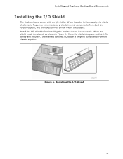
... chassis supplier. Installing and Replacing Desktop Board Components Installing the I/O Shield The Desktop Board comes with an I /O shield before installing the Desktop Board in the chassis. Press the shield into place so that it fits tightly and securely. When installed in Figure 6. Install the I /O shield. Figure 6. If the shield does not fit, obtain a properly sized shield from dust and foreign objects, and...
... chassis supplier. Installing and Replacing Desktop Board Components Installing the I/O Shield The Desktop Board comes with an I /O shield before installing the Desktop Board in the chassis. Press the shield into place so that it fits tightly and securely. When installed in Figure 6. Install the I /O shield. Figure 6. If the shield does not fit, obtain a properly sized shield from dust and foreign objects, and...

Product Guide
Page 53
Table 10. Use a shielded cable that have an unshielded cable attached to a USB port might not meet FCC Class B requirements, even if no pin) Pin Signal Name 2 TPA1- 4 Ground 6 ... and signal names for a full-speed USB device. 53 Table 9 shows the pin assignments and signal names for the IEEE 1394a header. Installing and Replacing Desktop Board Components IEEE 1394a Header Figure 27, F shows the location of the USB 2.0 headers. Table 9. USB 2.0 Header Signal Names USB Port A Pin Signal Name Pin 1 Power...
Table 10. Use a shielded cable that have an unshielded cable attached to a USB port might not meet FCC Class B requirements, even if no pin) Pin Signal Name 2 TPA1- 4 Ground 6 ... and signal names for a full-speed USB device. 53 Table 9 shows the pin assignments and signal names for the IEEE 1394a header. Installing and Replacing Desktop Board Components IEEE 1394a Header Figure 27, F shows the location of the USB 2.0 headers. Table 9. USB 2.0 Header Signal Names USB Port A Pin Signal Name Pin 1 Power...
Product Guide
Page 83
... Class B EMC testing and are not Class B EMC compliant before integration, then EMC testing may be required on a representative sample of certifications • External I/O cable shielding and filtering • Mounting, grounding, and bonding requirements • Keying connectors when mating the wrong connectors could be hazardous If the power supply and other...
... Class B EMC testing and are not Class B EMC compliant before integration, then EMC testing may be required on a representative sample of certifications • External I/O cable shielding and filtering • Mounting, grounding, and bonding requirements • Keying connectors when mating the wrong connectors could be hazardous If the power supply and other...