Product Guide
Page 6
Intel Desktop Board DQ965GF Product Guide Installing and Removing the Desktop Board 30 Installing and Removing a Processor 31 Installing a Processor 31 Installing the Processor Fan Heat Sink 34 Connecting the Processor Fan Heat Sink Cable 34 Removing ... 49 Connecting Power Cables 50 Other Connectors and Headers 51 Setting the BIOS Configuration Jumper 52 Clearing Passwords 53 Back Panel Connectors 54 3 Updating the BIOS Updating the BIOS with the Intel® Express BIOS Update Utility 61 Updating the BIOS with the ISO Image BIOS Update File or the Iflash Memory...
Intel Desktop Board DQ965GF Product Guide Installing and Removing the Desktop Board 30 Installing and Removing a Processor 31 Installing a Processor 31 Installing the Processor Fan Heat Sink 34 Connecting the Processor Fan Heat Sink Cable 34 Removing ... 49 Connecting Power Cables 50 Other Connectors and Headers 51 Setting the BIOS Configuration Jumper 52 Clearing Passwords 53 Back Panel Connectors 54 3 Updating the BIOS Updating the BIOS with the Intel® Express BIOS Update Utility 61 Updating the BIOS with the ISO Image BIOS Update File or the Iflash Memory...
Product Guide
Page 7
.... Removing a PCI Express x16 Card 41 20. Back Panel Audio Connectors 48 24. Back Panel Connectors 54 29. Removing the Battery 59 30. Original SATA Port Mapping for Desktop Board DQ965GF After RAID is Enabled 66 vii Desktop Board DQ965GF Components 11 2. Install the Processor 33 11. Use DDR2... the I/O Shield 29 5. Remove the Protective Socket Cover 32 9. Close the Load Plate 33 12. SATA Port Mapping for Desktop Board DQ965GF 65 31. Dual Channel Memory Configuration Example 2 36 15. Connecting the Serial ATA Cable 43 22. Location of the BIOS Configuration...
.... Removing a PCI Express x16 Card 41 20. Back Panel Audio Connectors 48 24. Back Panel Connectors 54 29. Removing the Battery 59 30. Original SATA Port Mapping for Desktop Board DQ965GF After RAID is Enabled 66 vii Desktop Board DQ965GF Components 11 2. Install the Processor 33 11. Use DDR2... the I/O Shield 29 5. Remove the Protective Socket Cover 32 9. Close the Load Plate 33 12. SATA Port Mapping for Desktop Board DQ965GF 65 31. Dual Channel Memory Configuration Example 2 36 15. Connecting the Serial ATA Cable 43 22. Location of the BIOS Configuration...
Product Guide
Page 8
...Names 47 10. Product Certification Markings 79 viii Feature Summary 9 2. Front Panel Header 46 8. Jumper Settings for Intel High Definition Audio 45 5. Lead-Free Board Markings 76 17. Front Panel Audio Header Signal Names for the BIOS Setup Program Modes 52 13. AC...97 Audio Header Signal Names 45 6. Alternate Front Panel Power LED Header 47 9. Beep Codes 69 14. USB 2.0 Header Signal Names 46 7. EMC Regulations 77 18. BIOS Error Messages 69 15. Desktop Board DQ965GF Components 12 3. Intel Desktop Board DQ965GF Product Guide Tables 1. HD Audio Link Header ...
...Names 47 10. Product Certification Markings 79 viii Feature Summary 9 2. Front Panel Header 46 8. Jumper Settings for Intel High Definition Audio 45 5. Lead-Free Board Markings 76 17. Front Panel Audio Header Signal Names for the BIOS Setup Program Modes 52 13. AC...97 Audio Header Signal Names 45 6. Alternate Front Panel Power LED Header 47 9. Beep Codes 69 14. USB 2.0 Header Signal Names 46 7. EMC Regulations 77 18. BIOS Error Messages 69 15. Desktop Board DQ965GF Components 12 3. Intel Desktop Board DQ965GF Product Guide Tables 1. HD Audio Link Header ...
Product Guide
Page 9
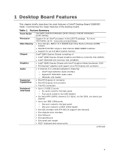
... chapter briefly describes the main features of the desktop board. Table 1 summarizes the major features of Intel® Desktop Board DQ965GF. Table 1. For more information, go to: www.intel.com/go/findcpu • Four 240-pin, DDR2 1.8 V SDRAM Dual Inline Memory Module (DIMM) sockets • 800/667/533 MHz single...) channels (3.0 Gb/s), via the ICH8, one device per channel • Up to two IEEE 1394a ports ― One port routed to the back panel ― One port routed to a IEEE 1394a header • One IDE interface with ATA-66/100 support (two devices) • One diskette drive...
... chapter briefly describes the main features of the desktop board. Table 1 summarizes the major features of Intel® Desktop Board DQ965GF. Table 1. For more information, go to: www.intel.com/go/findcpu • Four 240-pin, DDR2 1.8 V SDRAM Dual Inline Memory Module (DIMM) sockets • 800/667/533 MHz single...) channels (3.0 Gb/s), via the ICH8, one device per channel • Up to two IEEE 1394a ports ― One port routed to the back panel ― One port routed to a IEEE 1394a header • One IDE interface with ATA-66/100 support (two devices) • One diskette drive...
Product Guide
Page 10
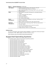
...panel Hardware Management • Intel® Quiet System Technology (Intel® QST) fan speed control • Three fan headers • Three fan sensing inputs used to monitor fan activity • Remote diode temperature sensing • Voltage sensing to detect out of range values Related Links: For more information about Desktop Board DQ965GF..., including the Technical Product Specification (TPS), BIOS updates, and device drivers, go to: http://support.intel.com/support/motherboards/desktop/ Supported Operating Systems The desktop board supports the...
...panel Hardware Management • Intel® Quiet System Technology (Intel® QST) fan speed control • Three fan headers • Three fan sensing inputs used to monitor fan activity • Remote diode temperature sensing • Voltage sensing to detect out of range values Related Links: For more information about Desktop Board DQ965GF..., including the Technical Product Specification (TPS), BIOS updates, and device drivers, go to: http://support.intel.com/support/motherboards/desktop/ Supported Operating Systems The desktop board supports the...
Product Guide
Page 12
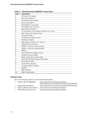
... panel header Serial ATA connectors Hi-speed USB 2.0 headers Speaker IDE connector IEEE 1394a header Related Links: Go to the following links for more information about: • Desktop Board DQ965GF • Supported processors • Audio software and utilities • LAN software and drivers http://www.intel.com/design/motherbd http://support.intel.com/support/motherboards/desktop http://support.intel...
... panel header Serial ATA connectors Hi-speed USB 2.0 headers Speaker IDE connector IEEE 1394a header Related Links: Go to the following links for more information about: • Desktop Board DQ965GF • Supported processors • Audio software and utilities • LAN software and drivers http://www.intel.com/design/motherbd http://support.intel.com/support/motherboards/desktop http://support.intel...

Product Guide
Page 15
...Hub (GMCH) with Direct Media Interface (DMI) interconnect • Intel 82801HO I/O Controller Hub (ICH8DO) with DMI interconnect Related Link: Go to the following : • 667 MHZ core frequency • Enhanced 3D graphics • Supports flat panel displays up to 1920 x 1080 at 75 Hz refresh rate ... exclusive graphics options. When a PCI Express x16 add-in card is installed, the GMA 3000 graphics controller is disabled. Desktop Board Features Intel® Q965 Express Chipset The Intel Q965 Express Chipset consists of system memory is used or a PCI Express x16 add-in card can be used.
...Hub (GMCH) with Direct Media Interface (DMI) interconnect • Intel 82801HO I/O Controller Hub (ICH8DO) with DMI interconnect Related Link: Go to the following : • 667 MHZ core frequency • Enhanced 3D graphics • Supports flat panel displays up to 1920 x 1080 at 75 Hz refresh rate ... exclusive graphics options. When a PCI Express x16 add-in card is installed, the GMA 3000 graphics controller is disabled. Desktop Board Features Intel® Q965 Express Chipset The Intel Q965 Express Chipset consists of system memory is used or a PCI Express x16 add-in card can be used.
Product Guide
Page 16
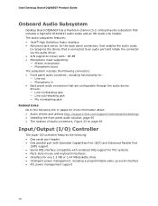
Intel Desktop Board DQ965GF Product Guide Onboard Audio Subsystem Desktop Board DQ965GF has a flexible 6-channel (5.1) onboard audio subsystem that are configurable through the audio device drivers: ― Line in/retasking jack ― Line out/...driver. • S/N (signal-to the following link or pages for more information about: • Audio drivers and utilities http://support.intel.com/support/motherboards/desktop/ • Installing the front panel audio solution, page 45 • The location of audio connectors, Figure 23 on page 48 Input/Output (I/O) Controller The super I/O ...
Intel Desktop Board DQ965GF Product Guide Onboard Audio Subsystem Desktop Board DQ965GF has a flexible 6-channel (5.1) onboard audio subsystem that are configurable through the audio device drivers: ― Line in/retasking jack ― Line out/...driver. • S/N (signal-to the following link or pages for more information about: • Audio drivers and utilities http://support.intel.com/support/motherboards/desktop/ • Installing the front panel audio solution, page 45 • The location of audio connectors, Figure 23 on page 48 Input/Output (I/O) Controller The super I/O ...
Product Guide
Page 17
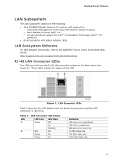
...; RJ-45 connector with status indicator LEDs LAN Subsystem Software For LAN software and drivers, refer to the DQ965GF link on Intel's World Wide Web site at: http://support.intel.com/support/motherboards/desktop RJ-45 LAN Connector LEDs Two LEDs are built into the RJ-45 LAN connector located on the back... panel (see Figure 2). LAN Connector LEDs Table 3 describes the LED states when the board is powered up and the LAN subsystem is...
...; RJ-45 connector with status indicator LEDs LAN Subsystem Software For LAN software and drivers, refer to the DQ965GF link on Intel's World Wide Web site at: http://support.intel.com/support/motherboards/desktop RJ-45 LAN Connector LEDs Two LEDs are built into the RJ-45 LAN connector located on the back... panel (see Figure 2). LAN Connector LEDs Table 3 describes the LED states when the board is powered up and the LAN subsystem is...
Product Guide
Page 19
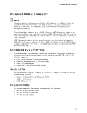
...• Older PIO Mode devices • Ultra DMA-33 and ATA-66/100 protocols Serial ATA The desktop board supports six Serial ATA channels (3.0 Gb/s) via ICH8 (six ports routed to the back panel and four ports routed to USB 1.1 operation. USB 2.0 ports are backward compatible with USB 1.1 devices.... Disabling Hi-Speed USB in the BIOS reverts all USB 2.0 ports to two internal USB 2.0 headers). The desktop board supports up to 10 USB 2.0 ports via...
...• Older PIO Mode devices • Ultra DMA-33 and ATA-66/100 protocols Serial ATA The desktop board supports six Serial ATA channels (3.0 Gb/s) via ICH8 (six ports routed to the back panel and four ports routed to USB 1.1 operation. USB 2.0 ports are backward compatible with USB 1.1 devices.... Disabling Hi-Speed USB in the BIOS reverts all USB 2.0 ports to two internal USB 2.0 headers). The desktop board supports up to 10 USB 2.0 ports via...
Product Guide
Page 23
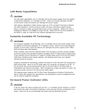
...in the BIOS in cards that powers up of the computer through a network. If the computer has a dual-colored power LED on the front panel, the sleep state is still lit, disconnect the power cord before installing or removing any attached devices. 23 When signaled by default in the S3...sleep state. While in the BIOS for Intel AMT Out of Band management to wake the computer. On-board Power Indicator LEDs CAUTION If the AC power has been switched off . Wake from the PCI and/or USB buses exceeds power supply capacity, the desktop board may lose register settings stored in power ...
...in the BIOS in cards that powers up of the computer through a network. If the computer has a dual-colored power LED on the front panel, the sleep state is still lit, disconnect the power cord before installing or removing any attached devices. 23 When signaled by default in the S3...sleep state. While in the BIOS for Intel AMT Out of Band management to wake the computer. On-board Power Indicator LEDs CAUTION If the AC power has been switched off . Wake from the PCI and/or USB buses exceeds power supply capacity, the desktop board may lose register settings stored in power ...
Product Guide
Page 27
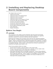
..., or modems before performing any procedures can result in personal injury or equipment damage. Some circuitry on the board can continue to operate even though the front panel power button is not available, you begin: • Always follow the steps in each procedure in the ... Electrostatic discharge (ESD) can damage components. Follow these guidelines before you how to: • Install the I/O shield • Install and remove the desktop board • Install and remove a processor • Install and remove memory • Install and remove a PCI Express x16 card • Connect the ...
..., or modems before performing any procedures can result in personal injury or equipment damage. Some circuitry on the board can continue to operate even though the front panel power button is not available, you begin: • Always follow the steps in each procedure in the ... Electrostatic discharge (ESD) can damage components. Follow these guidelines before you how to: • Install the I/O shield • Install and remove the desktop board • Install and remove a processor • Install and remove memory • Install and remove a PCI Express x16 card • Connect the ...
Product Guide
Page 40
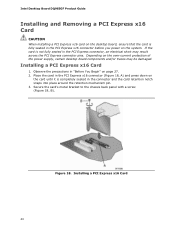
... the system. Secure the card's metal bracket to the chassis back panel with a screw (Figure 18, B). Figure 18. Installing a PCI Express x16 Card 40 Installing a PCI Express x16 Card 1. Intel Desktop Board DQ965GF Product Guide Installing and Removing a PCI Express x16 Card CAUTION When... installing a PCI Express x16 card on the desktop board, ensure that the card is fully seated in the PCI Express connector, an...
... the system. Secure the card's metal bracket to the chassis back panel with a screw (Figure 18, B). Figure 18. Installing a PCI Express x16 Card 40 Installing a PCI Express x16 Card 1. Intel Desktop Board DQ965GF Product Guide Installing and Removing a PCI Express x16 Card CAUTION When... installing a PCI Express x16 card on the desktop board, ensure that the card is fully seated in the PCI Express connector, an...

Product Guide
Page 41
Remove the screw (Figure 19, A) that secures the card's metal bracket to release the card from the connector: 1. Push down on page 27. 2. Pull the card straight up. Observe the precautions in "Before You Begin" on the card ejector lever (Figure 19, B) to the chassis back panel. 3. Figure 19. Installing and Replacing Desktop Board Components Removing the PCI Express x16 Card Follow these instructions to remove the PCI Express x16 card from the connector (C). 4. Removing a PCI Express x16 Card 41
Remove the screw (Figure 19, A) that secures the card's metal bracket to release the card from the connector: 1. Push down on page 27. 2. Pull the card straight up. Observe the precautions in "Before You Begin" on the card ejector lever (Figure 19, B) to the chassis back panel. 3. Figure 19. Installing and Replacing Desktop Board Components Removing the PCI Express x16 Card Follow these instructions to remove the PCI Express x16 card from the connector (C). 4. Removing a PCI Express x16 Card 41
Product Guide
Page 44
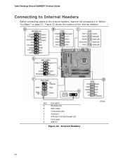
Internal Headers 44 Figure 22 shows the location of the internal headers. Intel Desktop Board DQ965GF Product Guide Connecting to Internal Headers Before connecting cables to the internal headers, observe the precautions in "Before You Begin" on page 27. Item Description A HD Audio Link B IEEE 1394a C Front panel audio D Serial port E Alternate front panel power LED F Front panel G USB 2.0 Figure 22.
Internal Headers 44 Figure 22 shows the location of the internal headers. Intel Desktop Board DQ965GF Product Guide Connecting to Internal Headers Before connecting cables to the internal headers, observe the precautions in "Before You Begin" on page 27. Item Description A HD Audio Link B IEEE 1394a C Front panel audio D Serial port E Alternate front panel power LED F Front panel G USB 2.0 Figure 22.

Product Guide
Page 45
... audio specification. Installing and Replacing Desktop Board Components Installing a Front Panel Audio Solution for the front panel audio header. Turn off the computer and disconnect the AC power cord. 3. Replace the cover. 45 Observe the precautions in the Intel® Audio Studio application. Table 4 shows the pin assignments for Intel® High Definition Audio Figure 22...
... audio specification. Installing and Replacing Desktop Board Components Installing a Front Panel Audio Solution for the front panel audio header. Turn off the computer and disconnect the AC power cord. 3. Replace the cover. 45 Observe the precautions in the Intel® Audio Studio application. Table 4 shows the pin assignments for Intel® High Definition Audio Figure 22...
Product Guide
Page 46
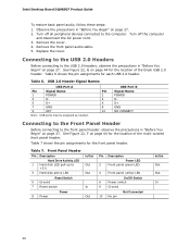
...and disconnect the AC power cord. 3. Table 7. Replace the cover. USB Port B Signal Name POWER DD+ GND NO CONNECT Connecting to the Front Panel Header Before connecting to +5 V 3 Hard disk active LED Reset Switch 5 Ground 7 Reset switch 9 Power Power In/Out Out Out In Out Pin...Out In 46 Front Panel Header Pin Description Hard Drive Activity LED 1 Hard disk LED pull-up to the front panel header, observe the precautions in "Before You Begin" on page 44 for the location of the black USB 2.0 header. Intel Desktop Board DQ965GF Product Guide To restore back panel audio, follow these ...
...and disconnect the AC power cord. 3. Table 7. Replace the cover. USB Port B Signal Name POWER DD+ GND NO CONNECT Connecting to the Front Panel Header Before connecting to +5 V 3 Hard disk active LED Reset Switch 5 Ground 7 Reset switch 9 Power Power In/Out Out Out In Out Pin...Out In 46 Front Panel Header Pin Description Hard Drive Activity LED 1 Hard disk LED pull-up to the front panel header, observe the precautions in "Before You Begin" on page 44 for the location of the black USB 2.0 header. Intel Desktop Board DQ965GF Product Guide To restore back panel audio, follow these ...

Product Guide
Page 47
...on page 44 shows the location of the alternate front panel power LED header. Table 10. Table 9. Installing and Replacing Desktop Board Components Connecting to the Alternate Front Panel Power LED Header Figure 22, E on pins 2 and 4 of the front panel header. Table 9 shows the pin assignments for the ...IEEE 1394a Header See Figure 22, B for the location of the serial port header. Alternate Front Panel Power LED Header Pin Description 1 Front panel green LED 2 No pin 3 Front panel yellow LED In/Out Out Out Connecting to the Serial Port Header See Figure 22, D for the...
...on page 44 shows the location of the alternate front panel power LED header. Table 10. Table 9. Installing and Replacing Desktop Board Components Connecting to the Alternate Front Panel Power LED Header Figure 22, E on pins 2 and 4 of the front panel header. Table 9 shows the pin assignments for the ...IEEE 1394a Header See Figure 22, B for the location of the serial port header. Alternate Front Panel Power LED Header Pin Description 1 Front panel green LED 2 No pin 3 Front panel yellow LED In/Out Out Out Connecting to the Serial Port Header See Figure 22, D for the...
Product Guide
Page 48
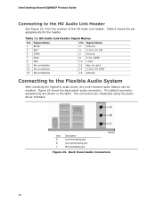
... in/retasking jack B Line out/retasking jack C Mic in the table. The default connector assignments are retaskable using the audio driver interface. Back Panel Audio Connectors 48 Intel Desktop Board DQ965GF Product Guide Connecting to the Flexible Audio System After installing the SigmaTel audio driver, the multi-channel audio feature can be enabled. HD Audio...
... in/retasking jack B Line out/retasking jack C Mic in the table. The default connector assignments are retaskable using the audio driver interface. Back Panel Audio Connectors 48 Intel Desktop Board DQ965GF Product Guide Connecting to the Flexible Audio System After installing the SigmaTel audio driver, the multi-channel audio feature can be enabled. HD Audio...

Product Guide
Page 54
Intel Desktop Board DQ965GF Product Guide Back Panel Connectors NOTE The line out connector, located on the back panel, is designed to this output. Figure 28. Figure 28 shows the back panel connectors. Back Panel Connectors 54 Poor audio quality may occur if passive (nonamplified) speakers are connected to power either headphones or amplified speakers only.
Intel Desktop Board DQ965GF Product Guide Back Panel Connectors NOTE The line out connector, located on the back panel, is designed to this output. Figure 28. Figure 28 shows the back panel connectors. Back Panel Connectors 54 Poor audio quality may occur if passive (nonamplified) speakers are connected to power either headphones or amplified speakers only.


