
Product Specification
Page 5
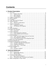
Contents 1 Product Description 1.1 Overview 9 1.1.1 Feature Summary 9 1.1.2 Board Layout 11 1.1.3 Block Diagram 13 1.2 Legacy Considerations 14 1.3 Online Support 14 1.4 Processor 14 1.5 Intel® Q67 Express Chipset 15 1.6 System Memory 15 1.6.1 Memory Configurations 16 1.7 Graphics Subsystem 18 1.7.1 Integrated Graphics 18 1.7.2 PCI Express x16 Graphics 19 1.8 USB 19 1.9 SATA Interfaces 20 1.10 Legacy I/O Controller 21 1.10.1 Serial...
Contents 1 Product Description 1.1 Overview 9 1.1.1 Feature Summary 9 1.1.2 Board Layout 11 1.1.3 Block Diagram 13 1.2 Legacy Considerations 14 1.3 Online Support 14 1.4 Processor 14 1.5 Intel® Q67 Express Chipset 15 1.6 System Memory 15 1.6.1 Memory Configurations 16 1.7 Graphics Subsystem 18 1.7.1 Integrated Graphics 18 1.7.2 PCI Express x16 Graphics 19 1.8 USB 19 1.9 SATA Interfaces 20 1.10 Legacy I/O Controller 21 1.10.1 Serial...

Product Specification
Page 7
...Connector Options 23 5. Back Panel Connectors 44 10. Components Shown in Figure 10 46 10. System Memory Map 43 9. Serial Port Header 47 11. Location of the Standby Power LED (Green 40 8. Intel MEBX Reset Header 56 15. Localized High Temperature Zones 61 Tables 1. LAN Connector LED States 25 ...5. SATA Connectors 48 17. Front Panel IEEE 1394a Header 49 21. Thermal Sensors and Fan Headers 27 7. Connection Diagram for Intel HD Audio 47 14. Front Panel Audio Header for Front Panel Header 51 12. Wake-up Devices and Events 36 8. Internal Mono Speaker Header...
...Connector Options 23 5. Back Panel Connectors 44 10. Components Shown in Figure 10 46 10. System Memory Map 43 9. Serial Port Header 47 11. Location of the Standby Power LED (Green 40 8. Intel MEBX Reset Header 56 15. Localized High Temperature Zones 61 Tables 1. LAN Connector LED States 25 ...5. SATA Connectors 48 17. Front Panel IEEE 1394a Header 49 21. Thermal Sensors and Fan Headers 27 7. Connection Diagram for Intel HD Audio 47 14. Front Panel Audio Header for Front Panel Header 51 12. Wake-up Devices and Events 36 8. Internal Mono Speaker Header...
Product Specification
Page 9
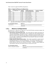
... Table 1 summarizes the major features of system memory with four DIMMs using 4 Gb memory technology • Support for non-ECC memory • Integrated graphics support for processors with Intel® Graphics Technology) ― External graphics interface controller ― Integrated memory controller Intel® Q67 Express Chipset consisting of the Intel® Q67 Platform Controller Hub (PCH) •...
... Table 1 summarizes the major features of system memory with four DIMMs using 4 Gb memory technology • Support for non-ECC memory • Integrated graphics support for processors with Intel® Graphics Technology) ― External graphics interface controller ― Integrated memory controller Intel® Q67 Express Chipset consisting of the Intel® Q67 Platform Controller Hub (PCH) •...
Product Specification
Page 14
...Intel Desktop Board DQ67SW Desktop Board Support Available configurations for this World Wide Web site: http://www.intel.com/products/motherboard/index.htm http://www.intel.com/p/en_US/support?iid=hdr+support http://ark.intel.com Supported processors Chipset information BIOS and driver updates Tested memory Integration information http://processormatch.intel.com http://www.intel...including (but not limited to : http://processormatch.intel.com CAUTION Use only the processors listed on power supply requirements for the Intel Desktop Board DQ67SW Visit this board. 14 Refer to Section ...
...Intel Desktop Board DQ67SW Desktop Board Support Available configurations for this World Wide Web site: http://www.intel.com/products/motherboard/index.htm http://www.intel.com/p/en_US/support?iid=hdr+support http://ark.intel.com Supported processors Chipset information BIOS and driver updates Tested memory Integration information http://processormatch.intel.com http://www.intel...including (but not limited to : http://processormatch.intel.com CAUTION Use only the processors listed on power supply requirements for the Intel Desktop Board DQ67SW Visit this board. 14 Refer to Section ...
Product Specification
Page 15
.... The PCH is installed, the BIOS will attempt to http://www.intel.com/products/desktop/chipsets/index.htm Chapter 2 1.6 System Memory The board has four DIMM sockets and supports the following memory features: • Two independent memory channels with 4 Gb memory technology). If non-SPD memory is a centralized controller for information on page 41 for the...
.... The PCH is installed, the BIOS will attempt to http://www.intel.com/products/desktop/chipsets/index.htm Chapter 2 1.6 System Memory The board has four DIMM sockets and supports the following memory features: • Two independent memory channels with 4 Gb memory technology). If non-SPD memory is a centralized controller for information on page 41 for the...
Product Specification
Page 16
... are unequal. Dual channel mode is installed or the memory capacities are equal. Technology and device width can vary from one channel to single channel bandwidth operation for real world applications. Intel Desktop Board DQ67SW Technical Product Specification Table 3 lists the supported DIMM configurations. For information about ... Memory Configuration examples Refer to the other .
... are unequal. Dual channel mode is installed or the memory capacities are equal. Technology and device width can vary from one channel to single channel bandwidth operation for real world applications. Intel Desktop Board DQ67SW Technical Product Specification Table 3 lists the supported DIMM configurations. For information about ... Memory Configuration examples Refer to the other .
Product Specification
Page 17
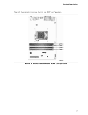
Memory Channel and DIMM Configuration 17 Product Description Figure 3 illustrates the memory channel and DIMM configuration. Figure 3.
Memory Channel and DIMM Configuration 17 Product Description Figure 3 illustrates the memory channel and DIMM configuration. Figure 3.
Product Specification
Page 26
... three years. Replace the battery with power applied through the power supply 5V STBY rail. Intel Desktop Board DQ67SW Technical Product Specification 1.13 Real-Time Clock Subsystem A coin-cell battery (CR2032) powers the real-time clock and CMOS memory. When the voltage drops below a certain level, the BIOS Setup program settings stored in...
... three years. Replace the battery with power applied through the power supply 5V STBY rail. Intel Desktop Board DQ67SW Technical Product Specification 1.13 Real-Time Clock Subsystem A coin-cell battery (CR2032) powers the real-time clock and CMOS memory. When the voltage drops below a certain level, the BIOS Setup program settings stored in...

Product Specification
Page 41
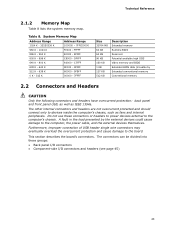
...Conventional and PCI Express add-in cards (256 MB) The board provides the capability to reclaim the physical memory overlapped by the memory mapped I /O that is no overlap of physical memory higher than what is shown in cards, PCI Express configuration space, BIOS (SPI Flash device), and ...• PCH base address registers PCI Express ports (up to CPU MTRR cache allocation. 41 Figure 8 shows a schematic of addressable system memory. Check with your operating system vendor. NOTE 32-bit operating systems may not be used when there is allocated for other system critical functions.
...Conventional and PCI Express add-in cards (256 MB) The board provides the capability to reclaim the physical memory overlapped by the memory mapped I /O that is no overlap of physical memory higher than what is shown in cards, PCI Express configuration space, BIOS (SPI Flash device), and ...• PCH base address registers PCI Express ports (up to CPU MTRR cache allocation. 41 Figure 8 shows a schematic of addressable system memory. Check with your operating system vendor. NOTE 32-bit operating systems may not be used when there is allocated for other system critical functions.
Product Specification
Page 43
...not overcurrent protected and should connect only to the computer's chassis. A fault in the load presented by Extended conventionfal mem) ory Conventional memory 2.2 Connectors and Headers CAUTION Only the following connectors and headers have overcurrent protection: back panel and front panel USB, as well as ... - 9FBFF 0 K - 512 K 00000 - 7FFFF Size 32764 MB 64 KB 64 KB 96 KB 160 KB 1 KB 127 KB 512 KB Description Extended memory Runtime BIOS Reserved Potential available high DOS Video me(mory andhBIOS Extended BIOS data (movable by the external devices could cause damage to the board...
...not overcurrent protected and should connect only to the computer's chassis. A fault in the load presented by Extended conventionfal mem) ory Conventional memory 2.2 Connectors and Headers CAUTION Only the following connectors and headers have overcurrent protection: back panel and front panel USB, as well as ... - 9FBFF 0 K - 512 K 00000 - 7FFFF Size 32764 MB 64 KB 64 KB 96 KB 160 KB 1 KB 127 KB 512 KB Description Extended memory Runtime BIOS Reserved Potential available high DOS Video me(mory andhBIOS Extended BIOS data (movable by the external devices could cause damage to the board...
Product Specification
Page 63
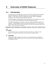
... bar is accessed by pressing the key after the Power-On Self-Test (POST) memory test begins and before the operating system boot begins. Maintenance Main Configuration Performance Security Power Boot Intel ME Exit NOTE The maintenance menu is displayed only when the board is stored in configure...in a 64 Mbit (8,192 KB) Serial Peripheral Interface Flash Memory (SPI Flash) device which can be updated using a set of utilities. The BIOS Setup program can be used . 3 Overview of BIOS Features 3.1 Introduction The board uses an Intel BIOS that Chipset-SATA Mode now defaults to AHCI. 63...
... bar is accessed by pressing the key after the Power-On Self-Test (POST) memory test begins and before the operating system boot begins. Maintenance Main Configuration Performance Security Power Boot Intel ME Exit NOTE The maintenance menu is displayed only when the board is stored in configure...in a 64 Mbit (8,192 KB) Serial Peripheral Interface Flash Memory (SPI Flash) device which can be updated using a set of utilities. The BIOS Setup program can be used . 3 Overview of BIOS Features 3.1 Introduction The board uses an Intel BIOS that Chipset-SATA Mode now defaults to AHCI. 63...
Product Specification
Page 64
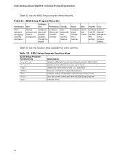
...processor information Displays processor and memory configuration Configures advanced features available through the chipset Configures Memory and Processor overrides Sets passwords and security features Power Boot Configures power management features Selects boot options Intel ME Exit Configure Intel ME and Intel AMT settings Saves or ...date/time) Executes command or selects the submenu Load the default configuration values for menu screens. Table 32. Intel Desktop Board DQ67SW Technical Product Specification Table 32 lists the BIOS Setup program menu features.
...processor information Displays processor and memory configuration Configures advanced features available through the chipset Configures Memory and Processor overrides Sets passwords and security features Power Boot Configures power management features Selects boot options Intel ME Exit Configure Intel ME and Intel AMT settings Saves or ...date/time) Executes command or selects the submenu Load the default configuration values for menu screens. Table 32. Intel Desktop Board DQ67SW Technical Product Specification Table 32 lists the BIOS Setup program menu features.
Product Specification
Page 65
...; BIOS data, such as the BIOS revision level • Fixed-system data, such as peripherals, serial numbers, and asset tags • Resource data, such as memory size, cache size, and processor speed • Dynamic data, such as event detection and error logging Non-Plug and Play operating systems require an additional...
...; BIOS data, such as the BIOS revision level • Fixed-system data, such as peripherals, serial numbers, and asset tags • Resource data, such as memory size, cache size, and processor speed • Dynamic data, such as event detection and error logging Non-Plug and Play operating systems require an additional...
Product Specification
Page 66
... from a file on a hard disk, a USB drive (a flash drive or a USB drive), or an optical drive. • Intel® Flash Memory Update Utility, which enables automated updating while in US English. 66 Intel Desktop Board DQ67SW Technical Product Specification 3.4 BIOS Updates The BIOS can be updated from a file on a hard disk, a USB drive (a flash...
... from a file on a hard disk, a USB drive (a flash drive or a USB drive), or an optical drive. • Intel® Flash Memory Update Utility, which enables automated updating while in US English. 66 Intel Desktop Board DQ67SW Technical Product Specification 3.4 BIOS Updates The BIOS can be updated from a file on a hard disk, a USB drive (a flash...
Product Specification
Page 73
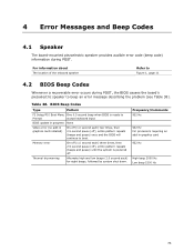
... Codes 4.1 Speaker The board-mounted piezoelectric speaker provides audible error code (beep code) information during POST, the BIOS causes the board's piezoelectric speaker to boot. Memory error On-off (1.0 second each) three times, then 2.5-second pause (off), entire pattern repeats (beeps and pause) until the system is ready to Prompt accept...
... Codes 4.1 Speaker The board-mounted piezoelectric speaker provides audible error code (beep code) information during POST, the BIOS causes the board's piezoelectric speaker to boot. Memory error On-off (1.0 second each) three times, then 2.5-second pause (off), entire pattern repeats (beeps and pause) until the system is ready to Prompt accept...
Product Specification
Page 74
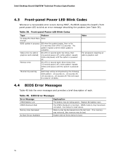
.... No Boot Device Available System did not find a device to blink an error message describing the problem (see Table 39). Intel Desktop Board DQ67SW Technical Product Specification 4.3 Front-panel Power LED Blink Codes Whenever a recoverable error occurs during POST, the BIOS causes the board... each ) two times, then 2.5-second pause (off . Replace the battery soon. CMOS Checksum Bad The CMOS checksum is complete. Memory Size Decreased Memory size has decreased since the last boot. Table 39. The pattern repeats until the system is powered off for 0.5 seconds, then ...
.... No Boot Device Available System did not find a device to blink an error message describing the problem (see Table 39). Intel Desktop Board DQ67SW Technical Product Specification 4.3 Front-panel Power LED Blink Codes Whenever a recoverable error occurs during POST, the BIOS causes the board... each ) two times, then 2.5-second pause (off . Replace the battery soon. CMOS Checksum Bad The CMOS checksum is complete. Memory Size Decreased Memory size has decreased since the last boot. Table 39. The pattern repeats until the system is powered off for 0.5 seconds, then ...
Product Specification
Page 75
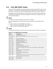
... values are listed in hexadecimal. S3, etc. For future use Input devices: Keyboard/Mouse. S2, 0x30 - Security (SEC) phase PEI phase pre MRC execution MRC memory detection PEI phase post MRC execution Recovery Platform DXE driver CPU Initialization (PEI, DXE, SMM) I /O port 80h. BDS Output devices: All output consoles. The POST...
... values are listed in hexadecimal. S3, etc. For future use Input devices: Keyboard/Mouse. S2, 0x30 - Security (SEC) phase PEI phase pre MRC execution MRC memory detection PEI phase post MRC execution Recovery Platform DXE driver CPU Initialization (PEI, DXE, SMM) I /O port 80h. BDS Output devices: All output consoles. The POST...
Product Specification
Page 76
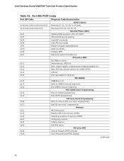
... Exit PEI over-clock programming Memory 0x21 0x23 MRC entry point Reading SPD from memory DIMMs 0x24 Detecting presence of memory DIMMs 0x27 Configuring memory 0x28 Testing memory 0x29 Exit MRC driver PEI after MRC 0x2A Start to Program MTRR Settings 0x2B Done Programming MTRR Settings continued 76 Intel Desktop Board DQ67SW Technical Product Specification Table 42...
... Exit PEI over-clock programming Memory 0x21 0x23 MRC entry point Reading SPD from memory DIMMs 0x24 Detecting presence of memory DIMMs 0x27 Configuring memory 0x28 Testing memory 0x29 Exit MRC driver PEI after MRC 0x2A Start to Program MTRR Settings 0x2B Done Programming MTRR Settings continued 76 Intel Desktop Board DQ67SW Technical Product Specification Table 42...
Product Specification
Page 77
... Init smm relocate bases 0x45 Smm relocate bases for APs 0x46 End CPU SMM Init CPU DXE Phase 0x47 CPU DXE Phase begin 0x48 Refresh memory space attributes according to MTRRs 0x49 Load the microcode if needed 0x4A Initialize strings to HII database 0x4B Initialize MP support 0x4C CPU DXE Phase...
... Init smm relocate bases 0x45 Smm relocate bases for APs 0x46 End CPU SMM Init CPU DXE Phase 0x47 CPU DXE Phase begin 0x48 Refresh memory space attributes according to MTRRs 0x49 Load the microcode if needed 0x4A Initialize strings to HII database 0x4B Initialize MP support 0x4C CPU DXE Phase...
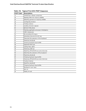
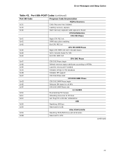
Product Specification
Page 80
Typical Port 80h POST Sequence POST Code Description 21 Initializing a chipset component 22 Reading SPD from memory DIMMs 23 Detecting presence of memory DIMMs 25 Configuring memory 28 Testing memory 34 Loading recovery capsule E4 Entered DXE phase 12 Starting application processor initialization 13 SMM initialization 50 ...90 Resetting keyboard 94 Clearing keyboard input buffer 5A Resetting PATA/SATA bus and all devices 28 Testing memory 90 Resetting keyboard 94 Clearing keyboard input buffer E7 Waiting for user input 01 INT 19 00 Ready to boot 80...
Typical Port 80h POST Sequence POST Code Description 21 Initializing a chipset component 22 Reading SPD from memory DIMMs 23 Detecting presence of memory DIMMs 25 Configuring memory 28 Testing memory 34 Loading recovery capsule E4 Entered DXE phase 12 Starting application processor initialization 13 SMM initialization 50 ...90 Resetting keyboard 94 Clearing keyboard input buffer 5A Resetting PATA/SATA bus and all devices 28 Testing memory 90 Resetting keyboard 94 Clearing keyboard input buffer E7 Waiting for user input 01 INT 19 00 Ready to boot 80...


