
Product Specification
Page 6
... System Management BIOS (SMBIOS 65 3.3 Legacy USB Support 65 3.4 BIOS Updates 66 3.4.1 Language Support 66 3.4.2 Custom Splash Screen 67 3.5 BIOS Recovery 67 3.6 Boot Options 68 3.6.1 Optical Drive Boot 68 3.6.2 Network Boot 68 3.6.3 Booting Without Attached Devices 68 3.6.4 Changing the Default Boot Device During POST 68 3.7 Hard Disk Drive Password Security Feature 69 3.8 BIOS Security Features 70 4 Error Messages and Beep Codes 4.1 Speaker 73 4.2 BIOS Beep Codes 73 4.3 Front-panel Power LED Blink Codes 74 4.4 BIOS Error Messages 74 4.5 Port 80h POST Codes 75 5 Regulatory...
... System Management BIOS (SMBIOS 65 3.3 Legacy USB Support 65 3.4 BIOS Updates 66 3.4.1 Language Support 66 3.4.2 Custom Splash Screen 67 3.5 BIOS Recovery 67 3.6 Boot Options 68 3.6.1 Optical Drive Boot 68 3.6.2 Network Boot 68 3.6.3 Booting Without Attached Devices 68 3.6.4 Changing the Default Boot Device During POST 68 3.7 Hard Disk Drive Password Security Feature 69 3.8 BIOS Security Features 70 4 Error Messages and Beep Codes 4.1 Speaker 73 4.2 BIOS Beep Codes 73 4.3 Front-panel Power LED Blink Codes 74 4.4 BIOS Error Messages 74 4.5 Port 80h POST Codes 75 5 Regulatory...
Product Specification
Page 7
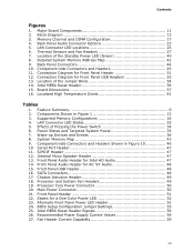
... Panel Audio Header for Front Panel Header 51 12. Alternate Front Panel Power LED Header 52 24. Connection Diagram for Intel HD Audio 47 14. Location of the Jumper Block 54 14. SATA Connectors 48 17. Main Power Connector 50 21. States for Front Panel USB Headers 53 13. Contents Figures 1. LAN Connector LED Locations 25 6. Detailed System Memory Address Map 42 9. Intel MEBX Reset Header 56 15. BIOS Setup Configuration Jumper Settings 55 25. Major Board Components 11 2. Back Panel Connectors 44 10. Wake-up Devices and Events 36 8. Chassis...
... Panel Audio Header for Front Panel Header 51 12. Alternate Front Panel Power LED Header 52 24. Connection Diagram for Intel HD Audio 47 14. Location of the Jumper Block 54 14. SATA Connectors 48 17. Main Power Connector 50 21. States for Front Panel USB Headers 53 13. Contents Figures 1. LAN Connector LED Locations 25 6. Detailed System Memory Address Map 42 9. Intel MEBX Reset Header 56 15. BIOS Setup Configuration Jumper Settings 55 25. Major Board Components 11 2. Back Panel Connectors 44 10. Wake-up Devices and Events 36 8. Chassis...
Product Specification
Page 8
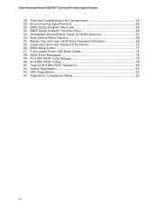
... 81 43. BIOS Setup Program Menu Bar 64 31. Typical Port 80h POST Sequence 80 42. Boot Device Menu Options 68 34. BIOS Beep Codes 73 37. Front-panel Power LED Blink Codes 74 38. Port 80h POST Codes 76 41. BIOS Setup Program Function Keys 64 32. Thermal Considerations for BIOS Recovery 67 33. EMC Regulations 85 44. Acceptable Drives/Media Types for Components 61 29. Master Key and User Hard Drive Password Functions 69 35. Intel Desktop Board DQ67EP Technical Product Specification 28. Regulatory...
... 81 43. BIOS Setup Program Menu Bar 64 31. Typical Port 80h POST Sequence 80 42. Boot Device Menu Options 68 34. BIOS Beep Codes 73 37. Front-panel Power LED Blink Codes 74 38. Port 80h POST Codes 76 41. BIOS Setup Program Function Keys 64 32. Thermal Considerations for BIOS Recovery 67 33. EMC Regulations 85 44. Acceptable Drives/Media Types for Components 61 29. Master Key and User Hard Drive Password Functions 69 35. Intel Desktop Board DQ67EP Technical Product Specification 28. Regulatory...
Product Specification
Page 10
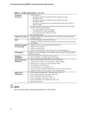
Intel Desktop Board DQ67EP Technical Product Specification Table 1. Feature Summary (continued) Peripheral Interfaces Legacy I/O Control BIOS Instantly Available PC Technology • Twelve USB ports: ― Two USB 3.0 ports are implemented with stacked back panel connectors (blue) ― Four USB 2.0 ports are implemented with stacked back panel connectors (black) ― Six USB 2.0 front panel ports are implemented through three dual-port internal headers • Six SATA interfaces through the Intel Q67 Express Chipset with Intel® Rapid Storage Technology RAID support: ―...
Intel Desktop Board DQ67EP Technical Product Specification Table 1. Feature Summary (continued) Peripheral Interfaces Legacy I/O Control BIOS Instantly Available PC Technology • Twelve USB ports: ― Two USB 3.0 ports are implemented with stacked back panel connectors (blue) ― Four USB 2.0 ports are implemented with stacked back panel connectors (black) ― Six USB 2.0 front panel ports are implemented through three dual-port internal headers • Six SATA interfaces through the Intel Q67 Express Chipset with Intel® Rapid Storage Technology RAID support: ―...
Product Specification
Page 14
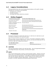
...) IDE drive connector 1.3 Online Support To find information about ... This board is designed to support processors with a maximum TDP of supported processors. Use of a 95 W TDP processor requires a custom thermal solution. See the Intel web site listed below for the Intel Desktop Board DQ67EP Visit this World Wide Web site: http://www.intel.com/products/motherboard/index.htm http://www.intel.com/p/en_US/support?iid=hdr+support http://ark.intel.com Supported processors Chipset information BIOS and driver updates...
...) IDE drive connector 1.3 Online Support To find information about ... This board is designed to support processors with a maximum TDP of supported processors. Use of a 95 W TDP processor requires a custom thermal solution. See the Intel web site listed below for the Intel Desktop Board DQ67EP Visit this World Wide Web site: http://www.intel.com/products/motherboard/index.htm http://www.intel.com/p/en_US/support?iid=hdr+support http://ark.intel.com Supported processors Chipset information BIOS and driver updates...
Product Specification
Page 20
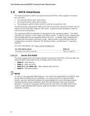
... the preferred mode for configurations using the F6 switch in the operating system installation process. 20 For information about installing drivers during Microsoft Windows XP installation, you must press F6 to Figure 10, page 45 1.9.1.1 Serial ATA RAID The board supports the Intel Rapid Storage Technology (Intel RST) which support one device per connector: • Two internal SATA 6 Gb/s ports (blue) • Two internal SATA 3 Gb/s ports (black) • Two backpanel eSATA 3 Gb/s ports for external connectivity (red...
... the preferred mode for configurations using the F6 switch in the operating system installation process. 20 For information about installing drivers during Microsoft Windows XP installation, you must press F6 to Figure 10, page 45 1.9.1.1 Serial ATA RAID The board supports the Intel Rapid Storage Technology (Intel RST) which support one device per connector: • Two internal SATA 6 Gb/s ports (blue) • Two internal SATA 3 Gb/s ports (black) • Two backpanel eSATA 3 Gb/s ports for external connectivity (red...

Product Specification
Page 53
...a connection diagram for the front panel USB headers. The POST card can interface with the Low Pin Count (LPC) Debug connector. Technical Reference 2.2.2.6 Front Panel USB Headers Figure 12 is useful for determining the point where an error occurred. Connection Diagram for Front Panel USB Headers 2.2.2.7 Low Pin Count (LPC) Debug Connector During the POST, the BIOS generates diagnostic progress codes (POST codes) to the USB 2.0 specification for high-speed USB devices. Displaying the POST codes requires a POST card that conforms to I/O port 80h. LPC Debug Connector Pin Signal...
...a connection diagram for the front panel USB headers. The POST card can interface with the Low Pin Count (LPC) Debug connector. Technical Reference 2.2.2.6 Front Panel USB Headers Figure 12 is useful for determining the point where an error occurred. Connection Diagram for Front Panel USB Headers 2.2.2.7 Low Pin Count (LPC) Debug Connector During the POST, the BIOS generates diagnostic progress codes (POST codes) to the USB 2.0 specification for high-speed USB devices. Displaying the POST codes requires a POST card that conforms to I/O port 80h. LPC Debug Connector Pin Signal...
Product Specification
Page 55
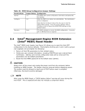
...The maintenance menu is expected and does not indicate a component failure. 55 Recovery None The BIOS attempts to clear the BIOS/CMOS settings. Otherwise, the board could be removed if the parameters are not default parameters. • Reset the Intel MEBX password to reach end of POST before installing an MEBX jumper. Note that this Configure mode is complete. This is displayed. BIOS Setup Configuration Jumper Settings Function/Mode Normal Configure Jumper Setting 1-2 2-3 Configuration The BIOS uses current configuration information and passwords for booting.
...The maintenance menu is expected and does not indicate a component failure. 55 Recovery None The BIOS attempts to clear the BIOS/CMOS settings. Otherwise, the board could be removed if the parameters are not default parameters. • Reset the Intel MEBX password to reach end of POST before installing an MEBX jumper. Note that this Configure mode is complete. This is displayed. BIOS Setup Configuration Jumper Settings Function/Mode Normal Configure Jumper Setting 1-2 2-3 Configuration The BIOS uses current configuration information and passwords for booting.
Product Specification
Page 63
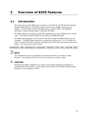
... be used . The BIOS displays a message during POST identifying the type of utilities. The menu bar is used to defaults may result in configure mode. Maintenance Main Configuration Performance Security Power Boot Intel ME Exit NOTE The maintenance menu is displayed only when the board is in the system becoming unbootable or corrupting the HDD if RAID is shown below. The SPI Flash contains the BIOS Setup program, POST, LAN EEPROM information, Plug and Play support, and other firmware.
... be used . The BIOS displays a message during POST identifying the type of utilities. The menu bar is used to defaults may result in configure mode. Maintenance Main Configuration Performance Security Power Boot Intel ME Exit NOTE The maintenance menu is displayed only when the board is in the system becoming unbootable or corrupting the HDD if RAID is shown below. The SPI Flash contains the BIOS Setup program, POST, LAN EEPROM information, Plug and Play support, and other firmware.
Product Specification
Page 69
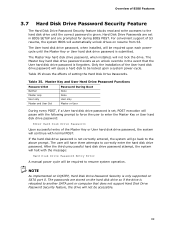
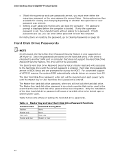
... enter the hard disk drive password. If the hard disk drive password is given. The User hard disk drive password, when installed, will be required upon a system power-cycle. Master Key and User Hard Drive Password Functions Password Set Password During Boot Neither None Master only None User only User only Master and User Set Master or User During every POST, if a User hard disk drive password is set in the event that does not support Hard Disk Drive Password Security feature, the drive will be required to resume system operation. Table 35. Hard Disk Drive...
... enter the hard disk drive password. If the hard disk drive password is given. The User hard disk drive password, when installed, will be required upon a system power-cycle. Master Key and User Hard Drive Password Functions Password Set Password During Boot Neither None Master only None User only User only Master and User Set Master or User During every POST, if a User hard disk drive password is set in the event that does not support Hard Disk Drive Password Security feature, the drive will be required to resume system operation. Table 35. Hard Disk Drive...
Product Specification
Page 70
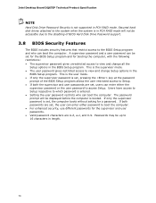
..., use different passwords for a password. Passwords may be accessible due to the disabling of the BIOS Setup program allows the user restricted access to Setup. • If both passwords are set, the user can enter either the supervisor password or the user password to the system when the system is in PCH RAID mode will be set , users can boot the computer. Secured hard disk drives attached to access Setup. A supervisor password and a user password can boot the computer. Intel Desktop Board DQ67EP Technical Product Specification NOTE Hard Disk Drive Password...
..., use different passwords for a password. Passwords may be accessible due to the disabling of the BIOS Setup program allows the user restricted access to Setup. • If both passwords are set, the user can enter either the supervisor password or the user password to the system when the system is in PCH RAID mode will be set , users can boot the computer. Secured hard disk drives attached to access Setup. A supervisor password and a user password can boot the computer. Intel Desktop Board DQ67EP Technical Product Specification NOTE Hard Disk Drive Password...
Product Specification
Page 74
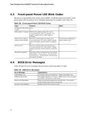
.... Replace the battery soon. Run Setup to boot. 74 No Boot Device Available System did not find a device to reset values. The pattern repeats until the system is powered off . Table 39. CMOS Checksum Bad The CMOS checksum is complete. If no add-in graphics card 4.4 BIOS Error Messages Table 39 lists the error messages and provides a brief description of 16 blinks. Front-panel Power LED Blink Codes Type Pattern F2 Setup/F10 Boot Menu...
.... Replace the battery soon. Run Setup to boot. 74 No Boot Device Available System did not find a device to reset values. The pattern repeats until the system is powered off . Table 39. CMOS Checksum Bad The CMOS checksum is complete. If no add-in graphics card 4.4 BIOS Error Messages Table 39 lists the error messages and provides a brief description of 16 blinks. Front-panel Power LED Blink Codes Type Pattern F2 Setup/F10 Boot Menu...
Product Specification
Page 75
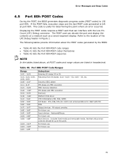
... a seven-segment display. Error Messages and Beep Codes 4.5 Port 80h POST Codes During the POST, the BIOS generates diagnostic progress codes (POST codes) to I /O Buses: PCI, USB, ATA etc. 0x5F is useful for determining the point where an error occurred. If the POST fails, execution stops and the last POST code generated is left at this point. Start with the Low Pin Count (LPC) Debug connector. This code is an unrecoverable error. The following...
... a seven-segment display. Error Messages and Beep Codes 4.5 Port 80h POST Codes During the POST, the BIOS generates diagnostic progress codes (POST codes) to I /O Buses: PCI, USB, ATA etc. 0x5F is useful for determining the point where an error occurred. If the POST fails, execution stops and the last POST code generated is left at this point. Start with the Low Pin Count (LPC) Debug connector. This code is an unrecoverable error. The following...
English Product Guide
Page 3
...; Desktop Board DQ67EP. Use Only for installation in personal computers (PC) for Intended Applications All Intel Desktop Boards are evaluated as follows: 1 Desktop Board Features: a summary of product features 2 Installing and Replacing Desktop Board Components: instructions on how to important information. Document Organization The chapters in this product for general audiences. The suitability of this Product Guide are used in this manual: CAUTION Cautions warn the user about board layout, component installation, BIOS update...
...; Desktop Board DQ67EP. Use Only for installation in personal computers (PC) for Intended Applications All Intel Desktop Boards are evaluated as follows: 1 Desktop Board Features: a summary of product features 2 Installing and Replacing Desktop Board Components: instructions on how to important information. Document Organization The chapters in this product for general audiences. The suitability of this Product Guide are used in this manual: CAUTION Cautions warn the user about board layout, component installation, BIOS update...
English Product Guide
Page 5
... Auto Configuration 21 PCI*/PCI Express Auto Configuration 21 BIOS Security Passwords 21 Hard Disk Drive Passwords 22 Platform Management and Protection 24 Intel® vPro™ Technology 24 Intel® Active Management Technology 24 Intel® Virtualization Technology 27 Intel® Trusted Execution Technology 27 Intel® Fast Call for Help 27 Trusted Platform Module (TPM 27 Fan Speed Control and Hardware Monitoring 28 Power Management 28 Software Support 28 Hardware Support 28 Onboard Speaker 31 Real-Time Clock Subsystem 31 2 Installing and Replacing Desktop Board...
... Auto Configuration 21 PCI*/PCI Express Auto Configuration 21 BIOS Security Passwords 21 Hard Disk Drive Passwords 22 Platform Management and Protection 24 Intel® vPro™ Technology 24 Intel® Active Management Technology 24 Intel® Virtualization Technology 27 Intel® Trusted Execution Technology 27 Intel® Fast Call for Help 27 Trusted Platform Module (TPM 27 Fan Speed Control and Hardware Monitoring 28 Power Management 28 Software Support 28 Hardware Support 28 Onboard Speaker 31 Real-Time Clock Subsystem 31 2 Installing and Replacing Desktop Board...
English Product Guide
Page 6
... Panel USB 2.0 Headers 52 Front Panel Header 52 Alternate Front Panel Power LED Header 53 Intel FCFH Header 53 Chassis Intrusion Header 53 S/PDIF Header 54 Internal Mono Speaker Header 54 Connecting to the Audio System 55 Connecting System Fan and Power Supply Cables 56 Connecting a System Fan Cable 56 Connecting Power Supply Cables 57 Setting the BIOS Configuration Jumper 58 Clearing Passwords in the BIOS Setup Program 59 Replacing the Battery 60 3 Updating the BIOS Updating the BIOS with the Intel® Express BIOS Update Utility 67 Updating the BIOS Using the F7 Function Key...
... Panel USB 2.0 Headers 52 Front Panel Header 52 Alternate Front Panel Power LED Header 53 Intel FCFH Header 53 Chassis Intrusion Header 53 S/PDIF Header 54 Internal Mono Speaker Header 54 Connecting to the Audio System 55 Connecting System Fan and Power Supply Cables 56 Connecting a System Fan Cable 56 Connecting Power Supply Cables 57 Setting the BIOS Configuration Jumper 58 Clearing Passwords in the BIOS Setup Program 59 Replacing the Battery 60 3 Updating the BIOS Updating the BIOS with the Intel® Express BIOS Update Utility 67 Updating the BIOS Using the F7 Function Key...
English Product Guide
Page 20
... a designated recovery drive. Intel RRT uses RAID 1 (mirroring) functionality to copy data from a designated master drive to the recovery drive when it is a feature of Independent Drives) levels: • RAID 0 - Intel RRT is reconnected. data striping and mirroring • RAID 5 - Intel Desktop Board DQ67EP Product Guide SATA RAID The Intel Q67 PCH supports Intel® Rapid Storage Technology (Intel® RST) which enables the following expansion capability: • One PCI Express 2.0 x16 interface • One PCI Express Mini Card interface 20...
... a designated recovery drive. Intel RRT uses RAID 1 (mirroring) functionality to copy data from a designated master drive to the recovery drive when it is a feature of Independent Drives) levels: • RAID 0 - Intel RRT is reconnected. data striping and mirroring • RAID 5 - Intel Desktop Board DQ67EP Product Guide SATA RAID The Intel Q67 PCH supports Intel® Rapid Storage Technology (Intel® RST) which enables the following expansion capability: • One PCI Express 2.0 x16 interface • One PCI Express Mini Card interface 20...
English Product Guide
Page 21
... manual configuration in the BIOS Setup program. PCI*/PCI Express Auto Configuration If you install a SATA device (such as a hard disk drive) in your computer, the autoconfiguration utility in the BIOS automatically detects and configures the device for your computer, the PCI/PCI Express auto-configuration utility in the BIOS automatically detects and configures the resources (IRQs, DMA channels, and I /O controller. You do not need to view and change all Setup options. The BIOS is set for the BIOS Setup and for booting the computer, with serialized IRQ support...
... manual configuration in the BIOS Setup program. PCI*/PCI Express Auto Configuration If you install a SATA device (such as a hard disk drive) in your computer, the autoconfiguration utility in the BIOS automatically detects and configures the device for your computer, the PCI/PCI Express auto-configuration utility in the BIOS automatically detects and configures the resources (IRQs, DMA channels, and I /O controller. You do not need to view and change all Setup options. The BIOS is set for the BIOS Setup and for booting the computer, with serialized IRQ support...
English Product Guide
Page 22
... that can boot the computer. Hard Disk Drive Passwords NOTE On this board, the Hard Disk Drive Password Security feature is booted. The board's Hard Disk Drive Password Security feature blocks read and write accesses to boot the computer. For convenient support of ACPI S3 resume, the system BIOS automatically unlocks drives on whether the supervisor or user password was entered. • Setting a user password restricts who can be accessible. Table 4. Setup options are then available for a password. Only the installation of setting the hard disk drive passwords.
... that can boot the computer. Hard Disk Drive Passwords NOTE On this board, the Hard Disk Drive Password Security feature is booted. The board's Hard Disk Drive Password Security feature blocks read and write accesses to boot the computer. For convenient support of ACPI S3 resume, the system BIOS automatically unlocks drives on whether the supervisor or user password was entered. • Setting a user password restricts who can be accessible. Table 4. Setup options are then available for a password. Only the installation of setting the hard disk drive passwords.
English Product Guide
Page 59
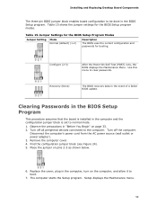
... 33. 2. Table 15. Disconnect the computer's power cord from the AC power source (wall outlet or power adapter). 3. Installing and Replacing Desktop Board Components The three-pin BIOS jumper block enables board configuration to normal mode. 1. Jumper Settings for the BIOS Setup Program Modes Jumper Setting Mode Normal (default) (1-2) Description The BIOS uses the current configuration and passwords for the BIOS Setup program modes. Observe the precautions in the BIOS Setup program. Remove the computer cover. 4. Replace the cover, plug in the event of a failed...
... 33. 2. Table 15. Disconnect the computer's power cord from the AC power source (wall outlet or power adapter). 3. Installing and Replacing Desktop Board Components The three-pin BIOS jumper block enables board configuration to normal mode. 1. Jumper Settings for the BIOS Setup Program Modes Jumper Setting Mode Normal (default) (1-2) Description The BIOS uses the current configuration and passwords for the BIOS Setup program modes. Observe the precautions in the BIOS Setup program. Remove the computer cover. 4. Replace the cover, plug in the event of a failed...


