

DP67DE Technical Product Specification
Page 5
... A description of the hardware used on Intel Desktop Board DP67DE A map of the resources of the Intel Desktop Board The features supported by the BIOS Setup program A description of the BIOS error messages, beep codes, and POST codes Regulatory compliance and battery disposal information ...Typographical Conventions This section contains information about Intel Desktop Board DP67DE and its components to provide detailed, technical information about the conventions...
... A description of the hardware used on Intel Desktop Board DP67DE A map of the resources of the Intel Desktop Board The features supported by the BIOS Setup program A description of the BIOS error messages, beep codes, and POST codes Regulatory compliance and battery disposal information ...Typographical Conventions This section contains information about Intel Desktop Board DP67DE and its components to provide detailed, technical information about the conventions...

DP67DE Technical Product Specification
Page 8
Intel Desktop Board DP67DE Technical Product Specification 2 Technical Reference 2.1 Memory Resources 37 2.1.1 Addressable Memory 37 2.1.2 Memory Map 39 2.2 Connectors and Headers 39 2.2.1 Back Panel Connectors 40 2.2.2 ... BIOS Recovery 63 3.8 Boot Options 64 3.8.1 Optical Drive Boot 64 3.8.2 Network Boot 64 3.8.3 Booting Without Attached Devices 64 3.8.4 Changing the Default Boot Device During POST 64 3.9 Adjusting Boot Speed 65 3.9.1 Peripheral Selection and Configuration 65 3.9.2 BIOS Boot Optimizations 65 3.10 BIOS Security Features 66 3.11 BIOS Performance Features 67 4...
Intel Desktop Board DP67DE Technical Product Specification 2 Technical Reference 2.1 Memory Resources 37 2.1.1 Addressable Memory 37 2.1.2 Memory Map 39 2.2 Connectors and Headers 39 2.2.1 Back Panel Connectors 40 2.2.2 ... BIOS Recovery 63 3.8 Boot Options 64 3.8.1 Optical Drive Boot 64 3.8.2 Network Boot 64 3.8.3 Booting Without Attached Devices 64 3.8.4 Changing the Default Boot Device During POST 64 3.9 Adjusting Boot Speed 65 3.9.1 Peripheral Selection and Configuration 65 3.9.2 BIOS Boot Optimizations 65 3.10 BIOS Security Features 66 3.11 BIOS Performance Features 67 4...
DP67DE Technical Product Specification
Page 10
...Keys 60 35. Supervisor and User Password Functions 66 38. BIOS Beep Codes 69 39. BIOS Error Messages 70 41. Port 80h POST Code Ranges 71 42. Regulatory Compliance Marks 85 x States for Components 56 31. Chassis Intrusion Header 44 18. States for a ...One-Color Power LED 48 25. Typical Port 80h POST Sequence 76 44. Port 80h POST Codes 72 43. Main Power Connector 46 23. BIOS Setup Configuration Jumper Settings 51 28. Intel Desktop Board DP67DE Technical Product Specification 17. Front Panel Header 47 24. Environmental Specifications...
...Keys 60 35. Supervisor and User Password Functions 66 38. BIOS Beep Codes 69 39. BIOS Error Messages 70 41. Port 80h POST Code Ranges 71 42. Regulatory Compliance Marks 85 x States for Components 56 31. Chassis Intrusion Header 44 18. States for a ...One-Color Power LED 48 25. Typical Port 80h POST Sequence 76 44. Port 80h POST Codes 72 43. Main Power Connector 46 23. BIOS Setup Configuration Jumper Settings 51 28. Intel Desktop Board DP67DE Technical Product Specification 17. Front Panel Header 47 24. Environmental Specifications...
DP67DE Technical Product Specification
Page 23
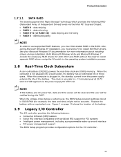
... install separate RAID drivers using the F6 switch in CMOS RAM (for example, the date and time) might not be notified during the POST. data mirroring • RAID 0+1 (or RAID 10) - distributed parity NOTE In order to install the RAID drivers. Also, during ...clock is not plugged into a wall socket, the battery has an estimated life of the battery. Product Description 1.7.1.1 SATA RAID The board supports Intel Rapid Storage Technology which provides the following features: • Consumer Infrared (CIR) headers • Serial IRQ interface compatible with serialized IRQ support ...
... install separate RAID drivers using the F6 switch in CMOS RAM (for example, the date and time) might not be notified during the POST. data mirroring • RAID 0+1 (or RAID 10) - distributed parity NOTE In order to install the RAID drivers. Also, during ...clock is not plugged into a wall socket, the battery has an estimated life of the battery. Product Description 1.7.1.1 SATA RAID The board supports Intel Rapid Storage Technology which provides the following features: • Consumer Infrared (CIR) headers • Serial IRQ interface compatible with serialized IRQ support ...

DP67DE Technical Product Specification
Page 47
... Drive Activity LED Header Pins 1 and 3 can be connected to an LED to provide a visual indicator that is closed, the board resets and runs the POST. 47 When the switch is normally open. Table 23 lists the signal names of the front panel header. Technical Reference 2.2.2.4 Front Panel Header This section...
... Drive Activity LED Header Pins 1 and 3 can be connected to an LED to provide a visual indicator that is closed, the board resets and runs the POST. 47 When the switch is normally open. Table 23 lists the signal names of the front panel header. Technical Reference 2.2.2.4 Front Panel Header This section...
DP67DE Technical Product Specification
Page 49
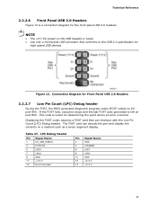
... Panel USB 2.0 Headers 2.2.2.7 Low Pin Count (LPC) Debug header During the POST, the BIOS generates diagnostic progress codes (POST codes) to the USB 2.0 specification for high-speed USB devices. Displaying the POST codes requires a POST card that conforms to I/O port 80h. LPC Debug Header Pin Signal Name 1.... NOTE • The +5 V DC power on a medium such as a seven-segment display. Table 27. If the POST fails, execution stops and the last POST code generated is useful for the front panel USB 2.0 headers. Technical Reference 2.2.2.6 Front Panel USB 2.0 Headers Figure 12 is fused...
... Panel USB 2.0 Headers 2.2.2.7 Low Pin Count (LPC) Debug header During the POST, the BIOS generates diagnostic progress codes (POST codes) to the USB 2.0 specification for high-speed USB devices. Displaying the POST codes requires a POST card that conforms to I/O port 80h. LPC Debug Header Pin Signal Name 1.... NOTE • The +5 V DC power on a medium such as a seven-segment display. Table 27. If the POST fails, execution stops and the last POST code generated is useful for the front panel USB 2.0 headers. Technical Reference 2.2.2.6 Front Panel USB 2.0 Headers Figure 12 is fused...

DP67DE Technical Product Specification
Page 51
... Setup Configuration Jumper Settings Function/Mode Normal Jumper Setting 1-2 Configuration The BIOS uses current configuration information and passwords for booting. Configure 2-3 Recovery None After the POST runs, Setup runs automatically. Press F9 (restore defaults) while in Configure mode to restore the BIOS/CMOS settings to recover the BIOS configuration. A recovery CD...
... Setup Configuration Jumper Settings Function/Mode Normal Jumper Setting 1-2 Configuration The BIOS uses current configuration information and passwords for booting. Configure 2-3 Recovery None After the POST runs, Setup runs automatically. Press F9 (restore defaults) while in Configure mode to restore the BIOS/CMOS settings to recover the BIOS configuration. A recovery CD...
DP67DE Technical Product Specification
Page 59
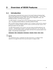
....86A. 3 Overview of BIOS and a revision code. The menu bar is accessed by pressing the key after the Power-On Self-Test (POST) memory test begins and before the operating system boot begins. Maintenance Main Configuration Performance Security Power Boot Exit NOTE The maintenance menu is displayed only...and reports if the two match. The BIOS Setup program is shown below. The BIOS displays a message during POST identifying the type of BIOS Features 3.1 Introduction The board uses an Intel BIOS that is stored in configure mode. Section 2.3 on page 50 shows how to view and change the ...
....86A. 3 Overview of BIOS and a revision code. The menu bar is accessed by pressing the key after the Power-On Self-Test (POST) memory test begins and before the operating system boot begins. Maintenance Main Configuration Performance Security Power Boot Exit NOTE The maintenance menu is displayed only...and reports if the two match. The BIOS Setup program is shown below. The BIOS displays a message during POST identifying the type of BIOS Features 3.1 Introduction The board uses an Intel BIOS that is stored in configure mode. Section 2.3 on page 50 shows how to view and change the ...

DP67DE Technical Product Specification
Page 61
... 6. After the operating system loads the USB drivers, all legacy and non-legacy USB devices are recognized by using Intel® Integrator Toolkit. 61 When you to use a USB keyboard to use SMBIOS. Additional USB legacy feature options can obtain ...Legacy USB support operates as event detection and error logging Non-Plug and Play operating systems require an additional interface for system components. POST completes. 5. Additional board information can obtain the system types, capabilities, operational status, and installation dates for obtaining the SMBIOS information....
... 6. After the operating system loads the USB drivers, all legacy and non-legacy USB devices are recognized by using Intel® Integrator Toolkit. 61 When you to use a USB keyboard to use SMBIOS. Additional USB legacy feature options can obtain ...Legacy USB support operates as event detection and error logging Non-Plug and Play operating systems require an additional interface for system components. POST completes. 5. Additional board information can obtain the system types, capabilities, operational status, and installation dates for obtaining the SMBIOS information....

DP67DE Technical Product Specification
Page 63
...interruption occurs, the BIOS could be used for BIOS recovery? Overview of BIOS Features 3.6.2 Custom Splash Screen During POST, an Intel® splash screen is available from Intel can and cannot be damaged. This splash screen can be used for BIOS recovery. For information about BIOS recovery... for example) Yes USB diskette drive (with a 1.44 MB diskette) No USB hard disk drive No For information about Intel Integrator Toolkit Additional Intel® software tools Refer to the SATA interface Yes USB removable drive (a USB Flash Drive, for BIOS Recovery Media Type...
...interruption occurs, the BIOS could be used for BIOS recovery? Overview of BIOS Features 3.6.2 Custom Splash Screen During POST, an Intel® splash screen is available from Intel can and cannot be damaged. This splash screen can be used for BIOS recovery. For information about BIOS recovery... for example) Yes USB diskette drive (with a 1.44 MB diskette) No USB hard disk drive No For information about Intel Integrator Toolkit Additional Intel® software tools Refer to the SATA interface Yes USB removable drive (a USB Flash Drive, for BIOS Recovery Media Type...

DP67DE Technical Product Specification
Page 64
... is supported in embedded applications, the BIOS has been designed so that after passing the POST, the operating system loader is listed as a boot device. This menu displays the list of available boot devices. Intel Desktop Board DP67DE Technical Product Specification 3.8 Boot Options In the BIOS Setup program, the user can be selected...
... is supported in embedded applications, the BIOS has been designed so that after passing the POST, the operating system loader is listed as a boot device. This menu displays the list of available boot devices. Intel Desktop Board DP67DE Technical Product Specification 3.8 Boot Options In the BIOS Setup program, the user can be selected...

DP67DE Technical Product Specification
Page 65
...8226; Eliminate unnecessary add-in adapter features, such as logo displays, screen repaints, or mode changes in less than eight seconds that the Intel logo screen (or a custom logo splash screen) will not be seen. If this condition should occur, it is possible to optimize the ...startup delays. • Select a CD-ROM drive with a fast initialization rate. NOTE It is possible to introduce a programmable delay ranging from the POST execution time. • In the Peripheral Configuration submenu, disable the LAN device if it will not be used. Overview of BIOS Features 3.9 Adjusting...
...8226; Eliminate unnecessary add-in adapter features, such as logo displays, screen repaints, or mode changes in less than eight seconds that the Intel logo screen (or a custom logo splash screen) will not be seen. If this condition should occur, it is possible to optimize the ...startup delays. • Select a CD-ROM drive with a fast initialization rate. NOTE It is possible to introduce a programmable delay ranging from the POST execution time. • In the Peripheral Configuration submenu, disable the LAN device if it will not be used. Overview of BIOS Features 3.9 Adjusting...

DP67DE Technical Product Specification
Page 69
... beep when BIOS is powered off. 4 Error Messages and Beep Codes 4.1 Speaker The board-mounted speaker provides audible error code (beep code) information during POST, the BIOS causes the board's speaker to beep an error message describing the problem (see Table 39). Memory error On-off (1.0 second each) three ... pattern repeats (beeps and pause) once and the BIOS will continue to Figure 1, page 13 4.2 BIOS Beep Codes Whenever a recoverable error occurs during POST. Frequency 932 Hz 932 Hz When no VGA option ROM is found. 932 Hz High beep 2000 Hz Low beep 1500 Hz 69 Table 39...
... beep when BIOS is powered off. 4 Error Messages and Beep Codes 4.1 Speaker The board-mounted speaker provides audible error code (beep code) information during POST, the BIOS causes the board's speaker to beep an error message describing the problem (see Table 39). Memory error On-off (1.0 second each) three ... pattern repeats (beeps and pause) once and the BIOS will continue to Figure 1, page 13 4.2 BIOS Beep Codes Whenever a recoverable error occurs during POST. Frequency 932 Hz 932 Hz When no VGA option ROM is found. 932 Hz High beep 2000 Hz Low beep 1500 Hz 69 Table 39...

DP67DE Technical Product Specification
Page 70
... to boot. 70 Memory error On-off (1.0 second each ) two times, then 2.5-second pause (off . Table 40. Intel Desktop Board DP67DE Technical Product Specification 4.3 Front-panel Power LED Blink Codes Whenever a recoverable error occurs during POST, the BIOS causes the board's front panel power LED to blink an error message describing the problem...
... to boot. 70 Memory error On-off (1.0 second each ) two times, then 2.5-second pause (off . Table 40. Intel Desktop Board DP67DE Technical Product Specification 4.3 Front-panel Power LED Blink Codes Whenever a recoverable error occurs during POST, the BIOS causes the board's front panel power LED to blink an error message describing the problem...
DP67DE Technical Product Specification
Page 71
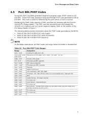
...etc. 0x08 - 0x0F Security (SEC) phase 0x11 0x1F 0x21 - 0x29 0x2A - 0x2F 0x31 - 0x35 PEI phase pre MRC execution MRC memory detection PEI phase post MRC execution Recovery 0x36 - 0x3F Platform DXE driver 0x41 - 0x4F CPU Initialization (PEI, DXE, SMM) 0x50 - 0x5F I /O port 80h. Refer to S5. ...Port 80h POST Code Ranges Range Subsystem 0x00 - 0x05 0x10, 0x20, 0x30, 0x40, 0x50 Entering SX states S0 to the location of the LPC Debug header in hexadecimal...
...etc. 0x08 - 0x0F Security (SEC) phase 0x11 0x1F 0x21 - 0x29 0x2A - 0x2F 0x31 - 0x35 PEI phase pre MRC execution MRC memory detection PEI phase post MRC execution Recovery 0x36 - 0x3F Platform DXE driver 0x41 - 0x4F CPU Initialization (PEI, DXE, SMM) 0x50 - 0x5F I /O port 80h. Refer to S5. ...Port 80h POST Code Ranges Range Subsystem 0x00 - 0x05 0x10, 0x20, 0x30, 0x40, 0x50 Entering SX states S0 to the location of the LPC Debug header in hexadecimal...

DP67DE Technical Product Specification
Page 72
Intel Desktop Board DP67DE Technical Product Specification Table 43. Port 80h POST Codes Port 80 Code Progress Code Enumeration ACPI S States 0x00,0x01,0x02,0x03,0x04,0x05 0x10,0x20,0x30,0x40,0x50 Entering S0, S2, S3, S4, ...
Intel Desktop Board DP67DE Technical Product Specification Table 43. Port 80h POST Codes Port 80 Code Progress Code Enumeration ACPI S States 0x00,0x01,0x02,0x03,0x04,0x05 0x10,0x20,0x30,0x40,0x50 Entering S0, S2, S3, S4, ...

DP67DE Technical Product Specification
Page 73
Error Messages and Beep Codes Table 43. Port 80h POST Codes (continued) Port 80 Code Progress Code Enumeration PEIMs/Recovery 0x31 0x33 0x34 Crisis Recovery has initiated Loading recovery capsule Start recovery capsule/ valid capsule ...
Error Messages and Beep Codes Table 43. Port 80h POST Codes (continued) Port 80 Code Progress Code Enumeration PEIMs/Recovery 0x31 0x33 0x34 Crisis Recovery has initiated Loading recovery capsule Start recovery capsule/ valid capsule ...

DP67DE Technical Product Specification
Page 74
Port 80h POST Codes (continued) Port 80 Code 0x60 0x61 0x62 0x63 0x64 0x65 0x66 0x67 0x68 0x69 0x6A 0x6B 0x6C 0x6D 0x6E 0x6F 0x90 0x91 0x92 0x93 ... Media Resetting fixed media Disabling fixed media 0xB2 0xB3 Detecting presence of a fixed media (IDE hard drive detection etc.) Enabling/configuring a fixed media continued 74 Intel Desktop Board DP67DE Technical Product Specification Table 43.
Port 80h POST Codes (continued) Port 80 Code 0x60 0x61 0x62 0x63 0x64 0x65 0x66 0x67 0x68 0x69 0x6A 0x6B 0x6C 0x6D 0x6E 0x6F 0x90 0x91 0x92 0x93 ... Media Resetting fixed media Disabling fixed media 0xB2 0xB3 Detecting presence of a fixed media (IDE hard drive detection etc.) Enabling/configuring a fixed media continued 74 Intel Desktop Board DP67DE Technical Product Specification Table 43.

DP67DE Technical Product Specification
Page 75
Port 80h POST Codes (continued) Port 80 Code Progress Code Enumeration Removable Media 0xB8 0xB9 0xBA Resetting removable media Disabling removable media Detecting presence of a removable media (IDE, ...
Port 80h POST Codes (continued) Port 80 Code Progress Code Enumeration Removable Media 0xB8 0xB9 0xBA Resetting removable media Disabling removable media Detecting presence of a removable media (IDE, ...

DP67DE Technical Product Specification
Page 76
Intel Desktop Board DP67DE Technical Product Specification Table 44. Typical Port 80h POST Sequence POST Code Description 21 Initializing a chipset component 22 Reading SPD from memory DIMMs 23 Detecting presence of memory DIMMs 25 Configuring memory 28 Testing memory 34 ...
Intel Desktop Board DP67DE Technical Product Specification Table 44. Typical Port 80h POST Sequence POST Code Description 21 Initializing a chipset component 22 Reading SPD from memory DIMMs 23 Detecting presence of memory DIMMs 25 Configuring memory 28 Testing memory 34 ...


