

DP67DE Technical Product Specification
Page 7
... 1.1.1 Feature Summary 11 1.1.2 Board Layout 13 1.1.3 Block Diagram 15 1.2 Legacy Considerations 16 1.3 Online Support 16 1.4 Processor 17 1.4.1 PCI Express x16 Graphics 17 1.5 System Memory 18 1.5.1 Memory Configurations 19 1.6 Intel® P67 Express Chipset 21 1.6.1 USB 21 1.7 SATA Interfaces 22 1.8 Real-Time Clock Subsystem 23 1.9 Legacy I/O Controller 23 1.9.1 Consumer Infrared (CIR 24 1.10 Audio...
... 1.1.1 Feature Summary 11 1.1.2 Board Layout 13 1.1.3 Block Diagram 15 1.2 Legacy Considerations 16 1.3 Online Support 16 1.4 Processor 17 1.4.1 PCI Express x16 Graphics 17 1.5 System Memory 18 1.5.1 Memory Configurations 19 1.6 Intel® P67 Express Chipset 21 1.6.1 USB 21 1.7 SATA Interfaces 22 1.8 Real-Time Clock Subsystem 23 1.9 Legacy I/O Controller 23 1.9.1 Consumer Infrared (CIR 24 1.10 Audio...

DP67DE Technical Product Specification
Page 8
Intel Desktop Board DP67DE Technical Product Specification 2 Technical Reference 2.1 Memory Resources 37 2.1.1 Addressable Memory 37 2.1.2 Memory Map 39 2.2 Connectors and Headers 39 2.2.1 Back Panel Connectors 40 2.2.2 Component-side Connectors and ...-in Board Considerations 54 2.6 Thermal Considerations 54 2.7 Reliability 57 2.8 Environmental 57 3 Overview of BIOS Features 3.1 Introduction 59 3.2 BIOS Flash Memory Organization 60 3.3 Resource Configuration 60 3.3.1 PCI Autoconfiguration 60 3.4 System Management BIOS (SMBIOS 61 3.5 Legacy USB Support 61 3.6 BIOS Updates 62...
Intel Desktop Board DP67DE Technical Product Specification 2 Technical Reference 2.1 Memory Resources 37 2.1.1 Addressable Memory 37 2.1.2 Memory Map 39 2.2 Connectors and Headers 39 2.2.1 Back Panel Connectors 40 2.2.2 Component-side Connectors and ...-in Board Considerations 54 2.6 Thermal Considerations 54 2.7 Reliability 57 2.8 Environmental 57 3 Overview of BIOS Features 3.1 Introduction 59 3.2 BIOS Flash Memory Organization 60 3.3 Resource Configuration 60 3.3.1 PCI Autoconfiguration 60 3.4 System Management BIOS (SMBIOS 61 3.5 Legacy USB Support 61 3.6 BIOS Updates 62...

DP67DE Technical Product Specification
Page 9
...Compliance 77 5.1.1 Safety Standards 77 5.1.2 European Union Declaration of Pressing the Power Switch 30 7. Detailed System Memory Address Map 38 9. Connection Diagram for Intel HD Audio 43 13. Front Panel Audio Header for Front Panel USB 2.0 Headers 49 13. Audio ...Jack Support 24 5. Back Panel Audio Connectors 25 5. Supported Memory Configurations 18 4. Component-side Connectors and Headers Shown in...
...Compliance 77 5.1.1 Safety Standards 77 5.1.2 European Union Declaration of Pressing the Power Switch 30 7. Detailed System Memory Address Map 38 9. Connection Diagram for Intel HD Audio 43 13. Front Panel Audio Header for Front Panel USB 2.0 Headers 49 13. Audio ...Jack Support 24 5. Back Panel Audio Connectors 25 5. Supported Memory Configurations 18 4. Component-side Connectors and Headers Shown in...
DP67DE Technical Product Specification
Page 11
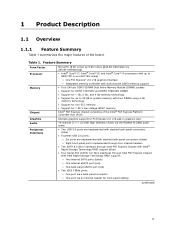
... a back panel connector ― One port via an internal header for 1.35 V low voltage JEDEC memory Intel® P67 Express Chipset consisting of the board. Table 1. Feature Summary Form Factor Processor Memory Chipset MicroATX (9.60 inches by 9.60 inches [243.84 millimeters by 243.84 millimeters]) •...; Intel® Core™ i7, Intel® Core™ i5, and Intel® Core™ i3 processors with up to 95W TDP...
... a back panel connector ― One port via an internal header for 1.35 V low voltage JEDEC memory Intel® P67 Express Chipset consisting of the board. Table 1. Feature Summary Form Factor Processor Memory Chipset MicroATX (9.60 inches by 9.60 inches [243.84 millimeters by 243.84 millimeters]) •...; Intel® Core™ i7, Intel® Core™ i5, and Intel® Core™ i3 processors with up to 95W TDP...

DP67DE Technical Product Specification
Page 16
... processors Chipset information BIOS and driver updates Tested memory Integration information http://processormatch.intel.com http://www.intel.com/products/desktop/chipsets/index.htm http://downloadcenter.intel.com http://www.intel.com/support/motherboards/desktop/sb/CS025414.htm http://www.intel.com/support/go/buildit 16 Intel Desktop Board DP67DE Technical Product Specification 1.2 Legacy Considerations This board differs...
... processors Chipset information BIOS and driver updates Tested memory Integration information http://processormatch.intel.com http://www.intel.com/products/desktop/chipsets/index.htm http://downloadcenter.intel.com http://www.intel.com/support/motherboards/desktop/sb/CS025414.htm http://www.intel.com/support/go/buildit 16 Intel Desktop Board DP67DE Technical Product Specification 1.2 Legacy Considerations This board differs...

DP67DE Technical Product Specification
Page 18
...the board should be impacted or the DIMMs may not function under the determined frequency. Intel Desktop Board DP67DE Technical Product Specification 1.5 System Memory The board has four DIMM sockets and supports the following memory features: • 1.5 V DDR3 SDRAM DIMMs with gold plated contacts, with the... restriction: Double-sided DIMMs with x16 organization are not supported. • 32 GB maximum total system memory (with DIMMs that support the Serial Presence Detect (SPD) data structure. Refer to : http://support.intel.com/support/motherboards/desktop/sb /CS-025414.htm 18
...the board should be impacted or the DIMMs may not function under the determined frequency. Intel Desktop Board DP67DE Technical Product Specification 1.5 System Memory The board has four DIMM sockets and supports the following memory features: • 1.5 V DDR3 SDRAM DIMMs with gold plated contacts, with the... restriction: Double-sided DIMMs with x16 organization are not supported. • 32 GB maximum total system memory (with DIMMs that support the Serial Presence Detect (SPD) data structure. Refer to : http://support.intel.com/support/motherboards/desktop/sb /CS-025414.htm 18

DP67DE Technical Product Specification
Page 19
... to the other . This mode provides the most flexible performance characteristics. To use flex mode, it is enabled when the installed memory capacities of both channels. Product Description 1.5.1 Memory Configurations The Intel Core i7, Intel Core i5, and Intel Core i3 processors in multiple zones of dual and single channel operation across the whole of...
... to the other . This mode provides the most flexible performance characteristics. To use flex mode, it is enabled when the installed memory capacities of both channels. Product Description 1.5.1 Memory Configurations The Intel Core i7, Intel Core i5, and Intel Core i3 processors in multiple zones of dual and single channel operation across the whole of...

DP67DE Technical Product Specification
Page 20
Intel Desktop Board DP67DE Technical Product Specification Figure 3 illustrates the memory channel and DIMM configuration. Memory Channel and DIMM Configuration NOTE The Intel Core i7, Intel Core i5, and Intel Core i3 processors require memory to be populated in your configuration. 20 For best memory performance always install memory into the blue DIMM memory sockets if only installing two DIMMs in the DIMM 1 (Channel A, DIMM 1) socket. Figure 3.
Intel Desktop Board DP67DE Technical Product Specification Figure 3 illustrates the memory channel and DIMM configuration. Memory Channel and DIMM Configuration NOTE The Intel Core i7, Intel Core i5, and Intel Core i3 processors require memory to be populated in your configuration. 20 For best memory performance always install memory into the blue DIMM memory sockets if only installing two DIMMs in the DIMM 1 (Channel A, DIMM 1) socket. Figure 3.
DP67DE Technical Product Specification
Page 23
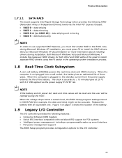
...RAID in the operating system installation process. 1.8 Real-Time Clock Subsystem A coin-cell battery (CR2032) powers the real-time clock and CMOS memory. When the computer is plugged in CMOS RAM (for both AHCI and RAID without the need to ± 13 minutes/year at 25 ... the computer is accurate to install separate RAID drivers using the F6 switch in the BIOS. Product Description 1.7.1.1 SATA RAID The board supports Intel Rapid Storage Technology which provides the following features: • Consumer Infrared (CIR) headers • Serial IRQ interface compatible with an equivalent ...
...RAID in the operating system installation process. 1.8 Real-Time Clock Subsystem A coin-cell battery (CR2032) powers the real-time clock and CMOS memory. When the computer is plugged in CMOS RAM (for both AHCI and RAID without the need to ± 13 minutes/year at 25 ... the computer is accurate to install separate RAID drivers using the F6 switch in the BIOS. Product Description 1.7.1.1 SATA RAID The board supports Intel Rapid Storage Technology which provides the following features: • Consumer Infrared (CIR) headers • Serial IRQ interface compatible with an equivalent ...

DP67DE Technical Product Specification
Page 37
... provides the capability to reclaim the physical memory overlapped by the memory mapped I/O logical address space. Figure 8 shows a schematic of addressable system memory. 2 Technical Reference 2.1 Memory Resources 2.1.1 Addressable Memory The board utilizes 32 GB of the system memory map. Typically the address space that has... chipset overhead resides above the 4 GB boundary. On a system that is no overlap of DRAM (total system memory). The board remaps physical memory from the top of usable DRAM boundary to the 4 GB boundary to system address space being allocated for other ...
... provides the capability to reclaim the physical memory overlapped by the memory mapped I/O logical address space. Figure 8 shows a schematic of addressable system memory. 2 Technical Reference 2.1 Memory Resources 2.1.1 Addressable Memory The board utilizes 32 GB of the system memory map. Typically the address space that has... chipset overhead resides above the 4 GB boundary. On a system that is no overlap of DRAM (total system memory). The board remaps physical memory from the top of usable DRAM boundary to the 4 GB boundary to system address space being allocated for other ...

DP67DE Technical Product Specification
Page 39
...to the PCI Conventional bus). The connectors can be divided into these connectors or headers to power devices external to the board. Video memory and BIOS Extended BIOS data (movable by the external devices could cause damage to the computer, the power cable, and the external ... to devices inside the computer's chassis, such as IEEE 1394a. A fault in the load presented by memory manager software) Extended conventional memory Conventional memory 2.2 Connectors and Headers CAUTION Only the following connectors and headers have overcurrent protection: back panel and front panel USB, as...
...to the PCI Conventional bus). The connectors can be divided into these connectors or headers to power devices external to the board. Video memory and BIOS Extended BIOS data (movable by the external devices could cause damage to the computer, the power cable, and the external ... to devices inside the computer's chassis, such as IEEE 1394a. A fault in the load presented by memory manager software) Extended conventional memory Conventional memory 2.2 Connectors and Headers CAUTION Only the following connectors and headers have overcurrent protection: back panel and front panel USB, as...
DP67DE Technical Product Specification
Page 59
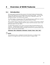
...BIOS and reports if the two match. The menu bar is accessed by pressing the key after the Power-On Self-Test (POST) memory test begins and before the operating system boot begins. The initial production BIOSs are identified as BAP6710H.86A. The BIOS Setup program is ... microcode version in configure mode. 59 The BIOS displays a message during POST identifying the type of BIOS Features 3.1 Introduction The board uses an Intel BIOS that is stored in configure mode. 3 Overview of BIOS and a revision code. Maintenance Main Configuration Performance Security Power Boot Exit NOTE The...
...BIOS and reports if the two match. The menu bar is accessed by pressing the key after the Power-On Self-Test (POST) memory test begins and before the operating system boot begins. The initial production BIOSs are identified as BAP6710H.86A. The BIOS Setup program is ... microcode version in configure mode. 59 The BIOS displays a message during POST identifying the type of BIOS Features 3.1 Introduction The board uses an Intel BIOS that is stored in configure mode. 3 Overview of BIOS and a revision code. Maintenance Main Configuration Performance Security Power Boot Exit NOTE The...
DP67DE Technical Product Specification
Page 60
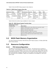
... set to Available in Setup are considered to be onboard or add-in card. 60 Table 35. Intel Desktop Board DP67DE Technical Product Specification Table 34 lists the BIOS Setup program menu features. Table 34. Autoconfiguration lets a user... and other system resources. tion Performance Security Clears passwords and displays processor information Displays processor and memory configuration Configures advanced features available through the chipset Configures Memory, Bus and Processor overrides Sets passwords and security features Power Configures power management features and power...
... set to Available in Setup are considered to be onboard or add-in card. 60 Table 35. Intel Desktop Board DP67DE Technical Product Specification Table 34 lists the BIOS Setup program menu features. Table 34. Autoconfiguration lets a user... and other system resources. tion Performance Security Clears passwords and displays processor information Displays processor and memory configuration Configures advanced features available through the chipset Configures Memory, Bus and Processor overrides Sets passwords and security features Power Configures power management features and power...

DP67DE Technical Product Specification
Page 61
... mice are not recognized during this period if Legacy USB support was set to Enabled. While the operating system is enabled by using Intel® Integrator Toolkit. 61 The MIF database defines the data and provides the method for such operating systems. Using this information. When... such as the BIOS revision level • Fixed-system data, such as peripherals, serial numbers, and asset tags • Resource data, such as memory size, cache size, and processor speed • Dynamic data, such as follows: 1. Additional USB legacy feature options can obtain the SMBIOS information. By...
... mice are not recognized during this period if Legacy USB support was set to Enabled. While the operating system is enabled by using Intel® Integrator Toolkit. 61 The MIF database defines the data and provides the method for such operating systems. Using this information. When... such as the BIOS revision level • Fixed-system data, such as peripherals, serial numbers, and asset tags • Resource data, such as memory size, cache size, and processor speed • Dynamic data, such as follows: 1. Additional USB legacy feature options can obtain the SMBIOS information. By...

DP67DE Technical Product Specification
Page 62
...drive), or a CD-ROM, or from the file location on the Web. • Intel® Flash Memory Update Utility, which requires booting from a file on the Intel World Wide Web site: • Intel® Express BIOS Update utility, which are supported in the Windows environment. NOTE Review ...BIOS Updates The BIOS can be updated using either of the following utilities, which enables automated updating while in US English. Intel Desktop Board DP67DE Technical Product Specification To install an operating system that supports USB, verify that the updated BIOS matches the target system to ...
...drive), or a CD-ROM, or from the file location on the Web. • Intel® Flash Memory Update Utility, which requires booting from a file on the Intel World Wide Web site: • Intel® Express BIOS Update utility, which are supported in the Windows environment. NOTE Review ...BIOS Updates The BIOS can be updated using either of the following utilities, which enables automated updating while in US English. Intel Desktop Board DP67DE Technical Product Specification To install an operating system that supports USB, verify that the updated BIOS matches the target system to ...

DP67DE Technical Product Specification
Page 67
Overview of BIOS Features 3.11 BIOS Performance Features The BIOS includes the following options to provide custom performance enhancements when using Intel Core i7, Intel Core i5, and Intel Core i3 processors in an LGA1155 socket. • Processor Maximum Non-Turbo Ratio (processor multiplier can only be adjusted down) • Memory multiplier adjustment • Memory voltage adjustment • Graphics multiplier adjustment 67
Overview of BIOS Features 3.11 BIOS Performance Features The BIOS includes the following options to provide custom performance enhancements when using Intel Core i7, Intel Core i5, and Intel Core i3 processors in an LGA1155 socket. • Processor Maximum Non-Turbo Ratio (processor multiplier can only be adjusted down) • Memory multiplier adjustment • Memory voltage adjustment • Graphics multiplier adjustment 67

DP67DE Technical Product Specification
Page 69
... is ready to accept keyboard input BIOS update in progress None Video error On-off (1.0 second each) two times, then 2.5-second pause (off . Table 39. Memory error On-off (1.0 second each ) for eight beeps, followed by system shut down. Thermal trip warning Alternate high and low beeps (1.0 second each ) three times...
... is ready to accept keyboard input BIOS update in progress None Video error On-off (1.0 second each) two times, then 2.5-second pause (off . Table 39. Memory error On-off (1.0 second each ) for eight beeps, followed by system shut down. Thermal trip warning Alternate high and low beeps (1.0 second each ) three times...

DP67DE Technical Product Specification
Page 70
... System did not find a device to reset values. Intel Desktop Board DP67DE Technical Product Specification 4.3 Front-panel Power LED Blink Codes Whenever a recoverable error occurs during POST, the BIOS causes the board's front panel power LED to blink an error message describing the problem (see Table 40). CMOS memory may be losing power.
... System did not find a device to reset values. Intel Desktop Board DP67DE Technical Product Specification 4.3 Front-panel Power LED Blink Codes Whenever a recoverable error occurs during POST, the BIOS causes the board's front panel power LED to blink an error message describing the problem (see Table 40). CMOS memory may be losing power.
DP67DE Technical Product Specification
Page 71
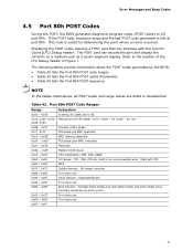
... are listed in Figure 1. S3, etc. 0x08 - 0x0F Security (SEC) phase 0x11 0x1F 0x21 - 0x29 0x2A - 0x2F 0x31 - 0x35 PEI phase pre MRC execution MRC memory detection PEI phase post MRC execution Recovery 0x36 - 0x3F Platform DXE driver 0x41 - 0x4F CPU Initialization (PEI, DXE, SMM) 0x50 - 0x5F I /O port 80h. S2, 0x30...
... are listed in Figure 1. S3, etc. 0x08 - 0x0F Security (SEC) phase 0x11 0x1F 0x21 - 0x29 0x2A - 0x2F 0x31 - 0x35 PEI phase pre MRC execution MRC memory detection PEI phase post MRC execution Recovery 0x36 - 0x3F Platform DXE driver 0x41 - 0x4F CPU Initialization (PEI, DXE, SMM) 0x50 - 0x5F I /O port 80h. S2, 0x30...

DP67DE Technical Product Specification
Page 72
... Exit PEI over-clock programming Memory 0x21 MRC entry point 0x23 Reading SPD from memory DIMMs 0x24 Detecting presence of memory DIMMs 0x27 Configuring memory 0x28 Testing memory 0x29 0x2A Exit MRC driver PEI after MRC Start to Program MTRR Settings 0x2B Done Programming MTRR Settings continued 72 Intel Desktop Board DP67DE Technical Product Specification Table 43...
... Exit PEI over-clock programming Memory 0x21 MRC entry point 0x23 Reading SPD from memory DIMMs 0x24 Detecting presence of memory DIMMs 0x27 Configuring memory 0x28 Testing memory 0x29 0x2A Exit MRC driver PEI after MRC Start to Program MTRR Settings 0x2B Done Programming MTRR Settings continued 72 Intel Desktop Board DP67DE Technical Product Specification Table 43...


