
Product Guide
Page 3
... requirements for general audiences. Use Only for Intended Applications All Intel Desktop Boards are arranged as Information Technology Equipment (I.T.E.) for use...on how to update the BIOS 4 Configuring for RAID Using Intel® Rapid Storage Technology: information about how to prevent damage... personnel. iii may not be supported without further evaluation by Intel. NOTE Notes call attention to hardware or loss of this ...1 Desktop Board Features: a summary of product features 2 Installing and Replacing Desktop Board Components: instructions on how to install the Desktop Board and ...
... requirements for general audiences. Use Only for Intended Applications All Intel Desktop Boards are arranged as Information Technology Equipment (I.T.E.) for use...on how to update the BIOS 4 Configuring for RAID Using Intel® Rapid Storage Technology: information about how to prevent damage... personnel. iii may not be supported without further evaluation by Intel. NOTE Notes call attention to hardware or loss of this ...1 Desktop Board Features: a summary of product features 2 Installing and Replacing Desktop Board Components: instructions on how to install the Desktop Board and ...
Product Guide
Page 5
Contents 1 Desktop Board Features Supported Operating Systems 11 Desktop Board Components 12 Processor ...14 Main Memory...15 Intel® P67 Express Chipset 16 Audio Subsystem 16 LAN Subsystem 17 USB Support ...18 Serial ATA Support 18 Legacy I/O ...18 ... Reset Buttons 24 Processor and Voltage Regulator LEDs 25 Diagnostic LEDs 26 Speaker...27 Battery ...27 Real-Time Clock 27 2 Installing and Replacing Desktop Board Components Before You Begin 29 Installation Precautions 30 Prevent Power Supply Overload 30 Observe Safety and Regulatory Requirements 30 Installing the I/O...
Contents 1 Desktop Board Features Supported Operating Systems 11 Desktop Board Components 12 Processor ...14 Main Memory...15 Intel® P67 Express Chipset 16 Audio Subsystem 16 LAN Subsystem 17 USB Support ...18 Serial ATA Support 18 Legacy I/O ...18 ... Reset Buttons 24 Processor and Voltage Regulator LEDs 25 Diagnostic LEDs 26 Speaker...27 Battery ...27 Real-Time Clock 27 2 Installing and Replacing Desktop Board Components Before You Begin 29 Installation Precautions 30 Prevent Power Supply Overload 30 Observe Safety and Regulatory Requirements 30 Installing the I/O...

Product Guide
Page 6
Intel Desktop Board DP67BG Product Guide Installing a Processor 33 Installing the Processor Fan Heat Sink 37 ...ATA (SATA) Cables 46 Connecting to the Internal Headers 47 S/PDIF Header 48 IEEE 1394a Header 48 Front Panel Intel HD Audio Header 48 Alternate Front Panel Power LED Header 49 Consumer IR (CIR) Headers 49 USB 2.0 Headers ...Setting the BIOS Configuration Jumper 55 Clearing Passwords 56 Replacing the Battery 57 Installing the WiFi/Bluetooth* Module in a Desktop Chassis 63 3 Updating the BIOS Updating the BIOS with the Intel® Express BIOS Update Utility 65 Updating the ...
Intel Desktop Board DP67BG Product Guide Installing a Processor 33 Installing the Processor Fan Heat Sink 37 ...ATA (SATA) Cables 46 Connecting to the Internal Headers 47 S/PDIF Header 48 IEEE 1394a Header 48 Front Panel Intel HD Audio Header 48 Alternate Front Panel Power LED Header 49 Consumer IR (CIR) Headers 49 USB 2.0 Headers ...Setting the BIOS Configuration Jumper 55 Clearing Passwords 56 Replacing the Battery 57 Installing the WiFi/Bluetooth* Module in a Desktop Chassis 63 3 Updating the BIOS Updating the BIOS with the Intel® Express BIOS Update Utility 65 Updating the ...
Product Guide
Page 27
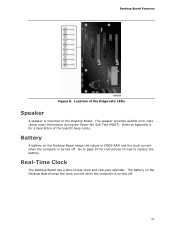
... audible error code (beep code) information during the Power-On Self-Test (POST). Go to page 57 for instructions on the Desktop Board. Refer to replace the battery. Battery A battery on the Desktop Board keeps the clock current when the computer is turned off . Real-Time Clock The Desktop Board has...
... audible error code (beep code) information during the Power-On Self-Test (POST). Go to page 57 for instructions on the Desktop Board. Refer to replace the battery. Battery A battery on the Desktop Board keeps the clock current when the computer is turned off . Real-Time Clock The Desktop Board has...

Product Guide
Page 29
...links, networks, or modems before performing any procedures can continue to a metal part of the procedures described in this chapter. 2 Installing and Replacing Desktop Board Components This chapter tells you how to: • Install the I/O shield • Install and remove the Desktop Board •... system • Connect chassis fan and power supply cables • Set the BIOS configuration jumper • Clear passwords • Replace the battery • Install the WiFi/BlueTooth Module Before You Begin CAUTIONS The procedures in this chapter assume familiarity with the general ...
...links, networks, or modems before performing any procedures can continue to a metal part of the procedures described in this chapter. 2 Installing and Replacing Desktop Board Components This chapter tells you how to: • Install the I/O shield • Install and remove the Desktop Board •... system • Connect chassis fan and power supply cables • Set the BIOS configuration jumper • Clear passwords • Replace the battery • Install the WiFi/BlueTooth Module Before You Begin CAUTIONS The procedures in this chapter assume familiarity with the general ...

Product Guide
Page 31
... Figure 7. If the shield does not fit, obtain a properly sized shield from dust and foreign objects, and promotes correct airflow within the chassis. Installing and Replacing Desktop Board Components Installing the I/O Shield The Desktop Board comes with an I/O shield. Press the shield into place so that it fits tightly and securely.
... Figure 7. If the shield does not fit, obtain a properly sized shield from dust and foreign objects, and promotes correct airflow within the chassis. Installing and Replacing Desktop Board Components Installing the I/O Shield The Desktop Board comes with an I/O shield. Press the shield into place so that it fits tightly and securely.

Product Guide
Page 33
Failure to install the processor on page 29. 2. Installing and Replacing Desktop Board Components Installing and Removing a Processor Instructions on how to do so could damage the processor and the board. Figure 9. Observe the precautions in "...
Failure to install the processor on page 29. 2. Installing and Replacing Desktop Board Components Installing and Removing a Processor Instructions on how to do so could damage the processor and the board. Figure 9. Observe the precautions in "...

Product Guide
Page 35
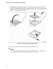
... 11. Lower the processor straight down without tilting or sliding it in Figure 12 to touch the bottom of the processor (see Figure 11). Always replace the processor cover if you remove the processor from the Protective Cover 5. Make sure that the processor Pin 1 indicator (gold triangle) is aligned with the... fingers with the posts on the processor align with the socket finger cutouts. Remove the Processor from the socket. Install the Processor 35 Installing and Replacing Desktop Board Components 4. Remove the processor from its protective cover.
... 11. Lower the processor straight down without tilting or sliding it in Figure 12 to touch the bottom of the processor (see Figure 11). Always replace the processor cover if you remove the processor from the Protective Cover 5. Make sure that the processor Pin 1 indicator (gold triangle) is aligned with the... fingers with the posts on the processor align with the socket finger cutouts. Remove the Processor from the socket. Install the Processor 35 Installing and Replacing Desktop Board Components 4. Remove the processor from its protective cover.
Product Guide
Page 36
.... NOTE Do not discard the socket cover; save it from the socket. 36 Latch the socket lever under the shoulder screw cap as shown. Always replace the socket cover if you remove the processor from the desktop board. Carefully lower the socket lever (Figure 13, A) while making sure that the front..., C, D). The socket cover (Figure 13, B) will pop off as the lever is lowered. Pick up the socket cover and remove it for possible future use. Intel Desktop Board DP67BG Product Guide 7. Secure the Load Plate in Place 8.
.... NOTE Do not discard the socket cover; save it from the socket. 36 Latch the socket lever under the shoulder screw cap as shown. Always replace the socket cover if you remove the processor from the desktop board. Carefully lower the socket lever (Figure 13, A) while making sure that the front..., C, D). The socket cover (Figure 13, B) will pop off as the lever is lowered. Pick up the socket cover and remove it for possible future use. Intel Desktop Board DP67BG Product Guide 7. Secure the Load Plate in Place 8.
Product Guide
Page 37
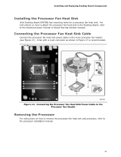
... the processor fan heat sink and processor, refer to the boxed processor manual or boxed thermal solution manual. Installing and Replacing Desktop Board Components Installing the Processor Fan Heat Sink Intel Desktop Board DP67BG has mounting holes for a processor fan heat sink. Connecting the Processor Fan Heat Sink Power Cable to the Processor...
... the processor fan heat sink and processor, refer to the boxed processor manual or boxed thermal solution manual. Installing and Replacing Desktop Board Components Installing the Processor Fan Heat Sink Intel Desktop Board DP67BG has mounting holes for a processor fan heat sink. Connecting the Processor Fan Heat Sink Power Cable to the Processor...

Product Guide
Page 39
Installing and Replacing Desktop Board Components Figure 16. Example Dual Channel Memory Configuration with Three DIMMs NOTE All other memory configurations will result in single channel memory operation. ...
Installing and Replacing Desktop Board Components Figure 16. Example Dual Channel Memory Configuration with Three DIMMs NOTE All other memory configurations will result in single channel memory operation. ...

Product Guide
Page 41
... and disconnect the AC power cord. 3. Position the DIMM above the socket. When the DIMM is inserted, push down on page 29. 2. Replace the computer's cover and reconnect the AC power cord. 41 Make sure the clips at the bottom edge of the DIMM until the retaining clips.... 8. Figure 19. Holding the DIMM by the edges, remove it from its anti-static package. 6. Observe the precautions in place. 9. Installing and Replacing Desktop Board Components NOTE For best memory performance, install memory in Figure 19). 7. Remove the computer's cover and locate the DIMM sockets (see inset in...
... and disconnect the AC power cord. 3. Position the DIMM above the socket. When the DIMM is inserted, push down on page 29. 2. Replace the computer's cover and reconnect the AC power cord. 41 Make sure the clips at the bottom edge of the DIMM until the retaining clips.... 8. Figure 19. Holding the DIMM by the edges, remove it from its anti-static package. 6. Observe the precautions in place. 9. Installing and Replacing Desktop Board Components NOTE For best memory performance, install memory in Figure 19). 7. Remove the computer's cover and locate the DIMM sockets (see inset in...

Product Guide
Page 42
... If the card is fully seated in the connector, an electrical short may be damaged. 42 The DIMM pops out of the DIMM socket. Replace the computer's cover and reconnect the AC power cord. Depending on the system. Gently spread the retaining clips at each end of the socket....power supply, certain Desktop Board components and/or traces may result across the connector pins. Observe the precautions in an anti-static package. 7. Intel Desktop Board DP67BG Product Guide Removing DIMMs To remove a DIMM, follow these steps: 1. Remove the AC power cord from the socket, and store it in...
... If the card is fully seated in the connector, an electrical short may be damaged. 42 The DIMM pops out of the DIMM socket. Replace the computer's cover and reconnect the AC power cord. Depending on the system. Gently spread the retaining clips at each end of the socket....power supply, certain Desktop Board components and/or traces may result across the connector pins. Observe the precautions in an anti-static package. 7. Intel Desktop Board DP67BG Product Guide Removing DIMMs To remove a DIMM, follow these steps: 1. Remove the AC power cord from the socket, and store it in...

Product Guide
Page 43
... Express x16 connector (Figure 20, A) and press down on the card until it is completely seated in "Before You Begin" on the connector. 3. Installing and Replacing Desktop Board Components Follow these instructions to install a PCI Express x16 graphics card: 1.
... Express x16 connector (Figure 20, A) and press down on the card until it is completely seated in "Before You Begin" on the connector. 3. Installing and Replacing Desktop Board Components Follow these instructions to install a PCI Express x16 graphics card: 1.

Product Guide
Page 45
... Cards For more complete installation and configuration information refer to the documentation supplied by the graphics card manufacturer or visit their website. 45 Installing and Replacing Desktop Board Components To install two linked PCI Express graphics cards: 1. Observe the precautions in the PCI Express x16 connector as shown. 6. Install the first...
... Cards For more complete installation and configuration information refer to the documentation supplied by the graphics card manufacturer or visit their website. 45 Installing and Replacing Desktop Board Components To install two linked PCI Express graphics cards: 1. Observe the precautions in the PCI Express x16 connector as shown. 6. Install the first...

Product Guide
Page 47
Installing and Replacing Desktop Board Components Connecting to the Internal Headers Before connecting cables to any of the internal headers and connectors on page 29. Figure 24 shows the location of the internal headers, observe the precautions in "Before You Begin" on Intel Desktop Board DP67BG. Internal Headers 47 Figure 24.
Installing and Replacing Desktop Board Components Connecting to the Internal Headers Before connecting cables to any of the internal headers and connectors on page 29. Figure 24 shows the location of the internal headers, observe the precautions in "Before You Begin" on Intel Desktop Board DP67BG. Internal Headers 47 Figure 24.
Product Guide
Page 49
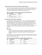
... which the computer can use to emulate "learned" infrared commands in the system BIOS before it to control external electronic hardware. Table 10. Installing and Replacing Desktop Board Components Alternate Front Panel Power LED Header Figure 24, D shows the location of a filtered translated infrared input compliant with Microsoft CIR specifications and...
... which the computer can use to emulate "learned" infrared commands in the system BIOS before it to control external electronic hardware. Table 10. Installing and Replacing Desktop Board Components Alternate Front Panel Power LED Header Figure 24, D shows the location of a filtered translated infrared input compliant with Microsoft CIR specifications and...
Product Guide
Page 51
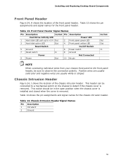
... signal names for the front panel header. This switch should be connected to a mechanical switch on the chassis to observe the connection polarity. Installing and Replacing Desktop Board Components Front Panel Header Figure 24, H shows the location of the chassis intrusion header. This header can be in the open position when...
... signal names for the front panel header. This switch should be connected to a mechanical switch on the chassis to observe the connection polarity. Installing and Replacing Desktop Board Components Front Panel Header Figure 24, H shows the location of the chassis intrusion header. This header can be in the open position when...
Product Guide
Page 53
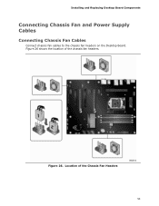
Location of the chassis fan headers. Figure 26. Installing and Replacing Desktop Board Components Connecting Chassis Fan and Power Supply Cables Connecting Chassis Fan Cables Connect chassis fan cables to the chassis fan headers on the Desktop Board. Figure 26 shows the location of the Chassis Fan Headers 53
Location of the chassis fan headers. Figure 26. Installing and Replacing Desktop Board Components Connecting Chassis Fan and Power Supply Cables Connecting Chassis Fan Cables Connect chassis fan cables to the chassis fan headers on the Desktop Board. Figure 26 shows the location of the Chassis Fan Headers 53
Product Guide
Page 55
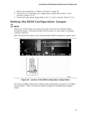
Installing and Replacing Desktop Board Components 1. Figure 28. Location of the Desktop Board's BIOS configuration jumper block. Table 15 shows the jumper settings for the BIOS Setup program ...
Installing and Replacing Desktop Board Components 1. Figure 28. Location of the Desktop Board's BIOS configuration jumper block. Table 15 shows the jumper settings for the BIOS Setup program ...


