
Product Guide
Page 5
... 11 Desktop Board Components 12 Processor ...14 Main Memory...15 Intel® P67 Express Chipset 16 Audio Subsystem 16 LAN Subsystem 17 USB Support ...18 Serial ATA Support 18 Legacy I/O ...18 Expandability...18 BIOS ...19 Serial ATA Auto Configuration 19 PCI* and PCI Express* Auto Configuration 19 Security Passwords 19 Back to BIOS...
... 11 Desktop Board Components 12 Processor ...14 Main Memory...15 Intel® P67 Express Chipset 16 Audio Subsystem 16 LAN Subsystem 17 USB Support ...18 Serial ATA Support 18 Legacy I/O ...18 Expandability...18 BIOS ...19 Serial ATA Auto Configuration 19 PCI* and PCI Express* Auto Configuration 19 Security Passwords 19 Back to BIOS...

Product Guide
Page 6
Intel Desktop Board DP67BG Product Guide Installing a Processor 33 Installing the Processor Fan Heat Sink 37 Connecting the... PCI Express x16 Graphics Card 42 Removing a PCI Express x16 Graphics Card 44 Installing Linked PCI Express Graphics Cards 44 Connecting the Serial ATA (SATA) Cables 46 Connecting to the Internal Headers 47 S/PDIF Header 48 IEEE 1394a Header 48 Front Panel Intel ...* Module in a Desktop Chassis 63 3 Updating the BIOS Updating the BIOS with the Intel® Express BIOS Update Utility 65 Updating the BIOS Using the F7 Function Key 66 Updating the BIOS with the...
Intel Desktop Board DP67BG Product Guide Installing a Processor 33 Installing the Processor Fan Heat Sink 37 Connecting the... PCI Express x16 Graphics Card 42 Removing a PCI Express x16 Graphics Card 44 Installing Linked PCI Express Graphics Cards 44 Connecting the Serial ATA (SATA) Cables 46 Connecting to the Internal Headers 47 S/PDIF Header 48 IEEE 1394a Header 48 Front Panel Intel ...* Module in a Desktop Chassis 63 3 Updating the BIOS Updating the BIOS with the Intel® Express BIOS Update Utility 65 Updating the BIOS Using the F7 Function Key 66 Updating the BIOS with the...
Product Guide
Page 7
... 88 Figures 1. Onboard Power and Reset Buttons 24 5. Use DDR3 DIMMs 40 19. Intel Desktop Board DP67BG Components 12 2. Unlatch the Socket Lever 33 10. Installing Linked PCI Express Graphics Cards 45 23. LAN Connector LEDs 17 3. Location of the Processor and Voltage... Regulator LEDs 25 6. Intel Desktop Board DP67BG Mounting Screw Hole Locations 32 9. Example Dual Channel Memory Configuration with Three...
... 88 Figures 1. Onboard Power and Reset Buttons 24 5. Use DDR3 DIMMs 40 19. Intel Desktop Board DP67BG Components 12 2. Unlatch the Socket Lever 33 10. Installing Linked PCI Express Graphics Cards 45 23. LAN Connector LEDs 17 3. Location of the Processor and Voltage... Regulator LEDs 25 6. Intel Desktop Board DP67BG Mounting Screw Hole Locations 32 9. Example Dual Channel Memory Configuration with Three...
Product Guide
Page 9
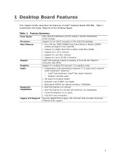
...memory • Support for multiple PCI Express* 2.0 graphics cards Audio • Independent multi-streaming 8-channel (7.1) audio and 2-channel audio subsystem, featuring: ― Intel® High Definition (Intel® HD) Audio interface ―...) Expansion Capabilities • One PCI Express 2.0 x16 port • One PCI Express 2.0 x8 port (x8 electrical; 16 compatible) • Three PCI Express 2.0 x1 ports • Two PCI* bus connectors Legacy I/O Support Nuvoton... MHz to 32 GB of memory Intel® P67 Express Chipset consisting of the Desktop Board. 1 Desktop Board ...
...memory • Support for multiple PCI Express* 2.0 graphics cards Audio • Independent multi-streaming 8-channel (7.1) audio and 2-channel audio subsystem, featuring: ― Intel® High Definition (Intel® HD) Audio interface ―...) Expansion Capabilities • One PCI Express 2.0 x16 port • One PCI Express 2.0 x8 port (x8 electrical; 16 compatible) • Three PCI Express 2.0 x1 ports • Two PCI* bus connectors Legacy I/O Support Nuvoton... MHz to 32 GB of memory Intel® P67 Express Chipset consisting of the Desktop Board. 1 Desktop Board ...
Product Guide
Page 10
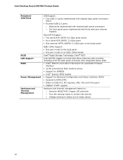
Intel Desktop Board DP67BG Product Guide Peripheral Interfaces RAID LAN Support BIOS Power Management Hardware and Thermal Management USB Support: • Two USB 3.0 ports implemented with stacked back panel ... firmware interface • 32 Mb symmetrical flash memory device • Support for SMBIOS • Intel® Express BIOS Update • Support for Advanced Configuration and Power Interface (ACPI) • Suspend to RAM (STR) • Wake on USB, PCI, PCI Express, LAN, CIR, and front panel • ENERGY STAR* capable Hardware and thermal management...
Intel Desktop Board DP67BG Product Guide Peripheral Interfaces RAID LAN Support BIOS Power Management Hardware and Thermal Management USB Support: • Two USB 3.0 ports implemented with stacked back panel ... firmware interface • 32 Mb symmetrical flash memory device • Support for SMBIOS • Intel® Express BIOS Update • Support for Advanced Configuration and Power Interface (ACPI) • Suspend to RAM (STR) • Wake on USB, PCI, PCI Express, LAN, CIR, and front panel • ENERGY STAR* capable Hardware and thermal management...
Product Guide
Page 13
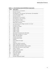
Intel Desktop Board DP67BG Components Label A B C D E F G H I J K L M N O P Q R S T U V W X Y Z AA BB CC DD EE FF GG HH II JJ Description PCI Express 2.0 x1 connector PCI bus connector PCI Express 2.0 x16 connector (x8 electrical; x16 compatible) Front panel audio header PCI bus connector PCI Express 2.0 x1 connector PCI Express 2.0 x16 connector Rear chassis fan header PCI Express 2.0 x1 connector Back panel connectors 12 V processor...
Intel Desktop Board DP67BG Components Label A B C D E F G H I J K L M N O P Q R S T U V W X Y Z AA BB CC DD EE FF GG HH II JJ Description PCI Express 2.0 x1 connector PCI bus connector PCI Express 2.0 x16 connector (x8 electrical; x16 compatible) Front panel audio header PCI bus connector PCI Express 2.0 x1 connector PCI Express 2.0 x16 connector Rear chassis fan header PCI Express 2.0 x1 connector Back panel connectors 12 V processor...

Product Guide
Page 17
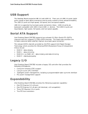
... The LAN subsystem includes: • Intel P67 PCH • Intel 82579V Gigabit (10/100/1000 Mb/s) Ethernet LAN controller • RJ-45 LAN connector with integrated status LEDs The subsystem features: • CSMA/CD protocol engine • LAN connect interface between PCH and the LAN controller • PCI bus power management Two LEDs...
... The LAN subsystem includes: • Intel P67 PCH • Intel 82579V Gigabit (10/100/1000 Mb/s) Ethernet LAN controller • RJ-45 LAN connector with integrated status LEDs The subsystem features: • CSMA/CD protocol engine • LAN connect interface between PCH and the LAN controller • PCI bus power management Two LEDs...
Product Guide
Page 18
...; Low pin count (LPC) interface • Intelligent power management, including a programmable wake up event interface • PCI power management support Expandability Intel Desktop Board DP67BG provides the following RAID (Redundant Array of Independent Drives) levels: • RAID 0 - USB 3.0 ports are SuperSpeed...blue). data mirroring • RAID 0+1 (or RAID 10) - x16 compatible) • Three PCI Express 2.0 x1 ports • Two PCI bus connectors 18 Intel Desktop Board DP67BG Product Guide USB Support The Desktop Board supports USB 2.0 and USB 3.0. data striping and data mirroring ...
...; Low pin count (LPC) interface • Intelligent power management, including a programmable wake up event interface • PCI power management support Expandability Intel Desktop Board DP67BG provides the following RAID (Redundant Array of Independent Drives) levels: • RAID 0 - USB 3.0 ports are SuperSpeed...blue). data mirroring • RAID 0+1 (or RAID 10) - x16 compatible) • Three PCI Express 2.0 x1 ports • Two PCI bus connectors 18 Intel Desktop Board DP67BG Product Guide USB Support The Desktop Board supports USB 2.0 and USB 3.0. data striping and data mirroring ...
Product Guide
Page 19
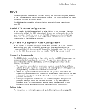
... as a hard drive) in your computer, the autoconfiguration utility in the BIOS automatically detects and configures the device for your computer, the PCI/PCI Express auto-configuration utility in the BIOS automatically detects and configures the resources (IRQs, DMA channels, and I/O space) for viewing and changing...for a password. Desktop Board Features BIOS The BIOS provides the Power-On Self-Test (POST), the BIOS Setup program, and the PCI/PCI Express and SATA auto-configuration utilities. The password prompt is displayed before the computer is set, pressing at the password prompt of ...
... as a hard drive) in your computer, the autoconfiguration utility in the BIOS automatically detects and configures the device for your computer, the PCI/PCI Express auto-configuration utility in the BIOS automatically detects and configures the resources (IRQs, DMA channels, and I/O space) for viewing and changing...for a password. Desktop Board Features BIOS The BIOS provides the Power-On Self-Test (POST), the BIOS Setup program, and the PCI/PCI Express and SATA auto-configuration utilities. The password prompt is displayed before the computer is set, pressing at the password prompt of ...

Product Guide
Page 22
...the hardware monitoring and control device. • All fan headers support closed-loop fan control that powers up of the computer through a network. Intel Desktop Board DP67BG Product Guide Fan Headers The function/operation of the fans is as needed. • All fan headers have a +12 V DC connection. ...header and three 4-pin chassis fan headers. LAN wakeup capabilities enable remote wake-up the computer. Failure to support multiple wake events from the PCI and/or USB buses exceeds power supply capacity, the Desktop Board may lose register settings stored in the ACPI S3, S4, or S5 ...
...the hardware monitoring and control device. • All fan headers support closed-loop fan control that powers up of the computer through a network. Intel Desktop Board DP67BG Product Guide Fan Headers The function/operation of the fans is as needed. • All fan headers have a +12 V DC connection. ...header and three 4-pin chassis fan headers. LAN wakeup capabilities enable remote wake-up the computer. Failure to support multiple wake events from the PCI and/or USB buses exceeds power supply capacity, the Desktop Board may lose register settings stored in the ACPI S3, S4, or S5 ...

Product Guide
Page 23
... in power management and can be off. If the computer has a dual-colored power LED on the PCI bus is asserted, the computer wakes from an ACPI S3, S4, or S5 state. 23 Wake from... wakes the computer from an ACPI S1, S3, S4, or S5 state. The Desktop Board supports the PCI Bus Power Management Interface Specification. PME# Signal Wake-up Support When the PME# signal on the front panel..., the sleep state is indicated by a wake-up Support When the WAKE# signal on the PCI Express bus is asserted, the computer wakes from an ACPI S1 or S3 state. USB bus activity wakes...
... in power management and can be off. If the computer has a dual-colored power LED on the PCI bus is asserted, the computer wakes from an ACPI S3, S4, or S5 state. 23 Wake from... wakes the computer from an ACPI S1, S3, S4, or S5 state. The Desktop Board supports the PCI Bus Power Management Interface Specification. PME# Signal Wake-up Support When the PME# signal on the front panel..., the sleep state is indicated by a wake-up Support When the WAKE# signal on the PCI Express bus is asserted, the computer wakes from an ACPI S1 or S3 state. USB bus activity wakes...
Product Guide
Page 24
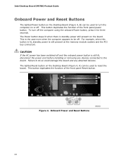
...or removing any attached devices. For example, when this button is lit, standby power is still present at the memory module sockets and the PCI bus connectors. This button duplicates the function of the front panel Reset button. Failure to do so could damage the board and any devices ... to reset the board. This button duplicates the function of the front panel power button. Figure 4. The lighted Reset button on the board. Intel Desktop Board DP67BG Product Guide Onboard Power and Reset Buttons The lighted Power button on the Desktop Board (Figure 4, B) can be used to turn off .
...or removing any attached devices. For example, when this button is lit, standby power is still present at the memory module sockets and the PCI bus connectors. This button duplicates the function of the front panel Reset button. Failure to do so could damage the board and any devices ... to reset the board. This button duplicates the function of the front panel power button. Figure 4. The lighted Reset button on the board. Intel Desktop Board DP67BG Product Guide Onboard Power and Reset Buttons The lighted Power button on the Desktop Board (Figure 4, B) can be used to turn off .

Product Guide
Page 29
...: • Install the I/O shield • Install and remove the Desktop Board • Install and remove a processor • Install and remove memory • Install and remove a PCI Express x16 graphics card • Connect the Serial ATA cables • Connect to the internal headers • Connect to operate even though the front panel...
...: • Install the I/O shield • Install and remove the Desktop Board • Install and remove a processor • Install and remove memory • Install and remove a PCI Express x16 graphics card • Connect the Serial ATA cables • Connect to the internal headers • Connect to operate even though the front panel...

Product Guide
Page 42
Intel Desktop Board DP67BG Product Guide Removing DIMMs To remove a DIMM, follow these steps: 1. Gently spread the retaining clips at each end of the power supply, certain Desktop Board components and/or traces may result across the connector pins. Installing and Removing PCI Express x16 Graphics Cards Installing a PCI Express x16 Graphics Card CAUTION When...
Intel Desktop Board DP67BG Product Guide Removing DIMMs To remove a DIMM, follow these steps: 1. Gently spread the retaining clips at each end of the power supply, certain Desktop Board components and/or traces may result across the connector pins. Installing and Removing PCI Express x16 Graphics Cards Installing a PCI Express x16 Graphics Card CAUTION When...

Product Guide
Page 43
...around the retention mechanism pin on page 29. 2. Connect the monitor cable to the graphics card according to install a PCI Express x16 graphics card: 1. Place the card in the PCI Express x16 connector (Figure 20, A) and press down on the card until it is completely seated in "Before You... Begin" on the connector. 3. Secure the card's metal bracket to the chassis back panel with a screw (Figure 20, B). 4. Installing a PCI Express x16 Graphics Card 43...
...around the retention mechanism pin on page 29. 2. Connect the monitor cable to the graphics card according to install a PCI Express x16 graphics card: 1. Place the card in the PCI Express x16 connector (Figure 20, A) and press down on the card until it is completely seated in "Before You... Begin" on the connector. 3. Secure the card's metal bracket to the chassis back panel with a screw (Figure 20, B). 4. Installing a PCI Express x16 Graphics Card 43...
Product Guide
Page 44
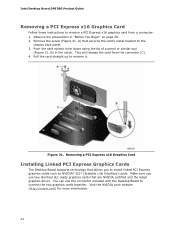
... Desktop Board supports technology that allows you use the connector included with the Desktop Board to remove it. Intel Desktop Board DP67BG Product Guide Removing a PCI Express x16 Graphics Card Follow these instructions to install linked PCI Express graphics cards such as NVIDIA* SLI* (Scalable Link Interface) cards. Remove the screw (Figure 21, A) that...
... Desktop Board supports technology that allows you use the connector included with the Desktop Board to remove it. Intel Desktop Board DP67BG Product Guide Removing a PCI Express x16 Graphics Card Follow these instructions to install linked PCI Express graphics cards such as NVIDIA* SLI* (Scalable Link Interface) cards. Remove the screw (Figure 21, A) that...

Product Guide
Page 45
...the connector and the card retention notch on the card snaps into place around the retention mechanism pin on page 29. 2. Installing Linked PCI Express Graphics Cards For more complete installation and configuration information refer to the manufacturer's instructions. Observe the precautions in the... PCI Express x16 connector as shown. 6. Install the first card in "Before You Begin" on the connector. 4. Connect the monitor cable to the ...
...the connector and the card retention notch on the card snaps into place around the retention mechanism pin on page 29. 2. Installing Linked PCI Express Graphics Cards For more complete installation and configuration information refer to the manufacturer's instructions. Observe the precautions in the... PCI Express x16 connector as shown. 6. Install the first card in "Before You Begin" on the connector. 4. Connect the monitor cable to the ...
Product Guide
Page 74
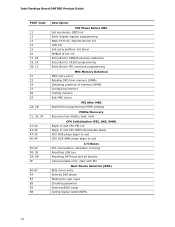
Intel Desktop Board DP67BG Product Guide POST Code 11 12 13 14 15 16 17, 18 19, 1A 1B, 1C 21 23 24 27 28 29 2A, 2B 31, ... CPU PEI init Begin to end CPU SMM init/relocate bases CPU DXE phase begin to end CPU DXE SMM phase begin to end I/O Buses PCI enumeration, allocation, hot plug Resetting USB bus Resetting SATA bus and all devices Unrecoverable error, start with PIC Boot Device Selection (BDS) BDS driver entry...
Intel Desktop Board DP67BG Product Guide POST Code 11 12 13 14 15 16 17, 18 19, 1A 1B, 1C 21 23 24 27 28 29 2A, 2B 31, ... CPU PEI init Begin to end CPU SMM init/relocate bases CPU DXE phase begin to end CPU DXE SMM phase begin to end I/O Buses PCI enumeration, allocation, hot plug Resetting USB bus Resetting SATA bus and all devices Unrecoverable error, start with PIC Boot Device Selection (BDS) BDS driver entry...
Product Specification
Page 5
... 9 1.1.1 Feature Summary 9 1.1.2 Board Layout 11 1.1.3 Block Diagram 13 1.2 Legacy Considerations 14 1.3 Online Support 14 1.4 Processor 14 1.5 System Memory 15 1.5.1 Memory Configurations 17 1.6 Intel® P67 Express Chipset 19 1.6.1 PCI Express x16 Graphics 19 1.6.2 USB 19 1.6.3 SATA Interfaces 19 1.7 Real-Time Clock Subsystem 21 1.8 Legacy I/O Controller 21 1.8.1 Consumer Infrared (CIR 21 1.9 Audio Subsystem...
... 9 1.1.1 Feature Summary 9 1.1.2 Board Layout 11 1.1.3 Block Diagram 13 1.2 Legacy Considerations 14 1.3 Online Support 14 1.4 Processor 14 1.5 System Memory 15 1.5.1 Memory Configurations 17 1.6 Intel® P67 Express Chipset 19 1.6.1 PCI Express x16 Graphics 19 1.6.2 USB 19 1.6.3 SATA Interfaces 19 1.7 Real-Time Clock Subsystem 21 1.8 Legacy I/O Controller 21 1.8.1 Consumer Infrared (CIR 21 1.9 Audio Subsystem...
Product Specification
Page 6
Intel Desktop Board DP67BG Technical Product Specification 2.2 Connectors and Headers 41 2.2.1 Back Panel Connectors 42 2.2.2 Component-side Connectors and Headers 43 2.3 Jumper Block 52 2.4 Mechanical ...56 2.6 Thermal Considerations 57 2.7 Reliability 59 2.8 Environmental 59 3 Overview of BIOS Features 3.1 Introduction 61 3.2 BIOS Flash Memory Organization 62 3.3 Resource Configuration 62 3.3.1 PCI Autoconfiguration 62 3.4 System Management BIOS (SMBIOS 63 3.5 Legacy USB Support 63 3.6 BIOS Updates 64 3.6.1 Language Support 64 3.6.2 Custom Splash Screen 65 3.7 BIOS Recovery 65...
Intel Desktop Board DP67BG Technical Product Specification 2.2 Connectors and Headers 41 2.2.1 Back Panel Connectors 42 2.2.2 Component-side Connectors and Headers 43 2.3 Jumper Block 52 2.4 Mechanical ...56 2.6 Thermal Considerations 57 2.7 Reliability 59 2.8 Environmental 59 3 Overview of BIOS Features 3.1 Introduction 61 3.2 BIOS Flash Memory Organization 62 3.3 Resource Configuration 62 3.3.1 PCI Autoconfiguration 62 3.4 System Management BIOS (SMBIOS 63 3.5 Legacy USB Support 63 3.6 BIOS Updates 64 3.6.1 Language Support 64 3.6.2 Custom Splash Screen 65 3.7 BIOS Recovery 65...

