
Product Guide
Page 5
Contents 1 Desktop Board Features Supported Operating Systems 11 Desktop Board Components 12 Processor ...14 Main Memory...15 Intel® P67 Express Chipset 16 Audio Subsystem 16 LAN Subsystem 17 USB Support ...18 Serial ATA Support 18 Legacy I/O ...18 Expandability...18 BIOS ...19 Serial ATA Auto Configuration 19 PCI* and... 21 ACPI 21 Hardware Support 21 Power Connectors 21 Fan Headers 22 LAN Wake Capabilities 22 Instantly Available PC Technology 22 Wake from USB 23 PME# Signal Wake-up Support 23 WAKE# Signal Wake-up Support 23 Wake from Consumer IR 23 Onboard Power and Reset...
Contents 1 Desktop Board Features Supported Operating Systems 11 Desktop Board Components 12 Processor ...14 Main Memory...15 Intel® P67 Express Chipset 16 Audio Subsystem 16 LAN Subsystem 17 USB Support ...18 Serial ATA Support 18 Legacy I/O ...18 Expandability...18 BIOS ...19 Serial ATA Auto Configuration 19 PCI* and... 21 ACPI 21 Hardware Support 21 Power Connectors 21 Fan Headers 22 LAN Wake Capabilities 22 Instantly Available PC Technology 22 Wake from USB 23 PME# Signal Wake-up Support 23 WAKE# Signal Wake-up Support 23 Wake from Consumer IR 23 Onboard Power and Reset...

Product Guide
Page 6
Intel Desktop Board DP67BG Product Guide Installing a Processor 33 Installing the Processor Fan Heat Sink 37 Connecting the ... Internal Headers 47 S/PDIF Header 48 IEEE 1394a Header 48 Front Panel Intel HD Audio Header 48 Alternate Front Panel Power LED Header 49 Consumer IR (CIR) Headers 49 USB 2.0 Headers 50 Front Panel Header 51 Chassis Intrusion Header 51 Connecting to.../Bluetooth* Module in a Desktop Chassis 63 3 Updating the BIOS Updating the BIOS with the Intel® Express BIOS Update Utility 65 Updating the BIOS Using the F7 Function Key 66 Updating the BIOS with the...
Intel Desktop Board DP67BG Product Guide Installing a Processor 33 Installing the Processor Fan Heat Sink 37 Connecting the ... Internal Headers 47 S/PDIF Header 48 IEEE 1394a Header 48 Front Panel Intel HD Audio Header 48 Alternate Front Panel Power LED Header 49 Consumer IR (CIR) Headers 49 USB 2.0 Headers 50 Front Panel Header 51 Chassis Intrusion Header 51 Connecting to.../Bluetooth* Module in a Desktop Chassis 63 3 Updating the BIOS Updating the BIOS with the Intel® Express BIOS Update Utility 65 Updating the BIOS Using the F7 Function Key 66 Updating the BIOS with the...
Product Guide
Page 8
...EMC Regulations 83 22. Back Panel Audio Connectors 52 26. S/PDIF Header Signal Names 48 7. BIOS Beep Codes 71 17. Intel Desktop Board DP67BG China RoHS Material Self Declaration Table 82 Tables 1. Removing the Battery 62 30. Jumper Settings for the BIOS Setup Program Modes ... Header Signal Names 51 15. Safety Standards 77 21. Location of the BIOS Configuration Jumper Block 55 29. USB 2.0 Header Signal Names 50 13. Feature Summary 9 2. Intel Desktop Board DP67BG Components 13 3. LAN Connector LEDs 17 5. BIOS Error Messages 72 19. Front Panel CIR Receiver (Input) ...
...EMC Regulations 83 22. Back Panel Audio Connectors 52 26. S/PDIF Header Signal Names 48 7. BIOS Beep Codes 71 17. Intel Desktop Board DP67BG China RoHS Material Self Declaration Table 82 Tables 1. Removing the Battery 62 30. Jumper Settings for the BIOS Setup Program Modes ... Header Signal Names 51 15. Safety Standards 77 21. Location of the BIOS Configuration Jumper Block 55 29. USB 2.0 Header Signal Names 50 13. Feature Summary 9 2. Intel Desktop Board DP67BG Components 13 3. LAN Connector LEDs 17 5. BIOS Error Messages 72 19. Front Panel CIR Receiver (Input) ...
Product Guide
Page 10
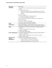
Intel Desktop Board DP67BG Product Guide Peripheral Interfaces RAID LAN Support BIOS Power Management Hardware and Thermal Management USB Support: • Two USB 3.0 ports implemented with stacked back panel connectors (blue) • Fourteen USB 2.0 ports: ― Eight ports implemented with stacked back panel connectors ...Mb symmetrical flash memory device • Support for SMBIOS • Intel® Express BIOS Update • Support for Advanced Configuration and Power Interface (ACPI) • Suspend to RAM (STR) • Wake on USB, PCI, PCI Express, LAN, CIR, and front panel •...
Intel Desktop Board DP67BG Product Guide Peripheral Interfaces RAID LAN Support BIOS Power Management Hardware and Thermal Management USB Support: • Two USB 3.0 ports implemented with stacked back panel connectors (blue) • Fourteen USB 2.0 ports: ― Eight ports implemented with stacked back panel connectors ...Mb symmetrical flash memory device • Support for SMBIOS • Intel® Express BIOS Update • Support for Advanced Configuration and Power Interface (ACPI) • Suspend to RAM (STR) • Wake on USB, PCI, PCI Express, LAN, CIR, and front panel •...
Product Guide
Page 13
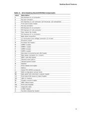
... configuration jumper block Back panel CIR transmitter (output) header Front panel CIR receiver (input) header USB 2.0 headers Chassis intrusion header IEEE 1394a header Front panel header Diagnostic LEDs S/PDIF header Auxiliary chassis fan header 13 Intel Desktop Board DP67BG Components Label A B C D E F G H I J K L M N O P Q R S T U V W X Y Z AA BB CC DD EE FF GG HH II JJ Description PCI...
... configuration jumper block Back panel CIR transmitter (output) header Front panel CIR receiver (input) header USB 2.0 headers Chassis intrusion header IEEE 1394a header Front panel header Diagnostic LEDs S/PDIF header Auxiliary chassis fan header 13 Intel Desktop Board DP67BG Components Label A B C D E F G H I J K L M N O P Q R S T U V W X Y Z AA BB CC DD EE FF GG HH II JJ Description PCI...
Product Guide
Page 18
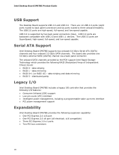
...striping and data mirroring • RAID 5 - USB 3.0 ports are 14 USB 2.0 ports (eight ports routed to back panel connectors and six ports routed to three onboard headers). Intel Desktop Board DP67BG Product Guide USB Support The Desktop Board supports USB 2.0 and USB 3.0. The board also provides one 3.0 Gb/s ... Express 2.0 x16 port • One PCI Express 2.0 x8 port (x8 electrical; The USB 3.0 ports are high-speed, full-speed, and low-speed capable. Serial ATA Support Intel Desktop Board DP67BG supports two onboard 6.0 Gb/s Serial ATA (SATA) channels and four onboard 3.0 Gb/s...
...striping and data mirroring • RAID 5 - USB 3.0 ports are 14 USB 2.0 ports (eight ports routed to back panel connectors and six ports routed to three onboard headers). Intel Desktop Board DP67BG Product Guide USB Support The Desktop Board supports USB 2.0 and USB 3.0. The board also provides one 3.0 Gb/s ... Express 2.0 x16 port • One PCI Express 2.0 x8 port (x8 electrical; The USB 3.0 ports are high-speed, full-speed, and low-speed capable. Serial ATA Support Intel Desktop Board DP67BG supports two onboard 6.0 Gb/s Serial ATA (SATA) channels and four onboard 3.0 Gb/s...
Product Guide
Page 21
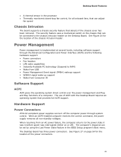
... the following hardware support: • Power connectors • Fan headers • LAN wake capabilities • Instantly Available PC technology (Suspend to RAM) • Wake from USB • Power Management Event signal (PME#) wakeup support • WAKE# signal wake-up support • Wake from an AC power failure, the computer returns to...
... the following hardware support: • Power connectors • Fan headers • LAN wake capabilities • Instantly Available PC technology (Suspend to RAM) • Wake from USB • Power Management Event signal (PME#) wakeup support • WAKE# signal wake-up support • Wake from an AC power failure, the computer returns to...

Product Guide
Page 22
... are off when the computer is in memory. 22 If the standby current necessary to support multiple wake events from the PCI and/or USB buses exceeds power supply capacity, the Desktop Board may lose register settings stored in the ACPI S3, S4, or S5 state. •...or effect ACPI S3 sleep state functionality. Power supplies used with this Desktop Board must be capable of delivering adequate +5 V standby current. Intel Desktop Board DP67BG Product Guide Fan Headers The function/operation of the fans is wired to a tachometer input of the hardware monitoring and control device. •...
... are off when the computer is in memory. 22 If the standby current necessary to support multiple wake events from the PCI and/or USB buses exceeds power supply capacity, the Desktop Board may lose register settings stored in the ACPI S3, S4, or S5 state. •...or effect ACPI S3 sleep state functionality. Power supplies used with this Desktop Board must be capable of delivering adequate +5 V standby current. Intel Desktop Board DP67BG Product Guide Fan Headers The function/operation of the fans is wired to a tachometer input of the hardware monitoring and control device. •...

Product Guide
Page 23
... PCI Bus Power Management Interface Specification. Wake from Consumer IR Consumer IR device activity wakes the computer from USB. Wake from USB NOTE Wake from USB requires the use of a USB peripheral that supports Wake from USB and an operating system that support this specification can participate in power management and can be off. Add... from an ACPI S1, S3, S4, or S5 state. Desktop Board Features Instantly Available PC technology enables the board to its last known awake state. USB bus activity wakes the computer from an ACPI S1 or S3 state.
... PCI Bus Power Management Interface Specification. Wake from Consumer IR Consumer IR device activity wakes the computer from USB. Wake from USB NOTE Wake from USB requires the use of a USB peripheral that supports Wake from USB and an operating system that support this specification can participate in power management and can be off. Add... from an ACPI S1, S3, S4, or S5 state. Desktop Board Features Instantly Available PC technology enables the board to its last known awake state. USB bus activity wakes the computer from an ACPI S1 or S3 state.

Product Guide
Page 26
Intel Desktop Board DP67BG Product Guide Diagnostic LEDs The Desktop Board provides eight ...Timer Fire/ Back to BIOS LED Color Red B Processor Initialization Green C Memory Initialization Green D Video Initialization Green E USB Initialization Green F Hard Drive Initialization Green G Option ROM Initialization Green H OS Start Green Description When the watch dog.... This LED will flash when the option ROM activity starts. This LED will flash when the USB initialization activity starts. When the BIOS starts an activity such as memory initialization, the corresponding LED ...
Intel Desktop Board DP67BG Product Guide Diagnostic LEDs The Desktop Board provides eight ...Timer Fire/ Back to BIOS LED Color Red B Processor Initialization Green C Memory Initialization Green D Video Initialization Green E USB Initialization Green F Hard Drive Initialization Green G Option ROM Initialization Green H OS Start Green Description When the watch dog.... This LED will flash when the option ROM activity starts. This LED will flash when the USB initialization activity starts. When the BIOS starts an activity such as memory initialization, the corresponding LED ...

Product Guide
Page 50
... Figure 24, G shows the location of the USB 2.0 headers. Intel Desktop Board DP67BG Product Guide Table 11. Table 12 shows the pin assignments and signal names for a full-speed USB device. 50 Each USB header can be used to the cable. Table 12. USB 2.0 Header Signal Names USB Port A Pin Signal Name Pin 1 Power (+5 V) 2 3 D- 4 5 D+ 6 7 Ground 8 9 Key 10...
... Figure 24, G shows the location of the USB 2.0 headers. Intel Desktop Board DP67BG Product Guide Table 11. Table 12 shows the pin assignments and signal names for a full-speed USB device. 50 Each USB header can be used to the cable. Table 12. USB 2.0 Header Signal Names USB Port A Pin Signal Name Pin 1 Power (+5 V) 2 3 D- 4 5 D+ 6 7 Ground 8 9 Key 10...
Product Guide
Page 63
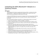
...from an empty 5-1/4 inch drive bay in the chassis bezel (Figure 30, A). 4. Observe the precautions in the chassis bezel while routing the USB cable into the chassis through the empty drive bay (Figure 30, E). 8. Remove the plastic cover from the internal drive bay (Figure 30...drive bay cover in "Before You Begin" on the Desktop Board (see Figure 1, DD for a typical desktop chassis is included with Intel Desktop Board DP67BG in your desktop system allows you to connect to wireless networks and Bluetooth peripherals. The recommended installation procedure for locations) (Figure 30, ...
...from an empty 5-1/4 inch drive bay in the chassis bezel (Figure 30, A). 4. Observe the precautions in the chassis bezel while routing the USB cable into the chassis through the empty drive bay (Figure 30, E). 8. Remove the plastic cover from the internal drive bay (Figure 30...drive bay cover in "Before You Begin" on the Desktop Board (see Figure 1, DD for a typical desktop chassis is included with Intel Desktop Board DP67BG in your desktop system allows you to connect to wireless networks and Bluetooth peripherals. The recommended installation procedure for locations) (Figure 30, ...
Product Guide
Page 65
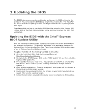
... is required. Navigate to complete the BIOS update. 65 This step is included in an automated update utility that combines the functionality of the Intel Flash Memory Update Utility and the ease of use of Windows-based installation wizards. Double-click the executable file from the location on the ...view and change the BIOS settings for multiple identical systems.) 4. Download the file to a removable USB device. This is useful if you can update the system BIOS while in the dialog boxes to the DP67BG page. Click on your hard drive. (You can also save this file to your hard ...
... is required. Navigate to complete the BIOS update. 65 This step is included in an automated update utility that combines the functionality of the Intel Flash Memory Update Utility and the ease of use of Windows-based installation wizards. Double-click the executable file from the location on the ...view and change the BIOS settings for multiple identical systems.) 4. Download the file to a removable USB device. This is useful if you can update the system BIOS while in the dialog boxes to the DP67BG page. Click on your hard drive. (You can also save this file to your hard ...
Product Guide
Page 66
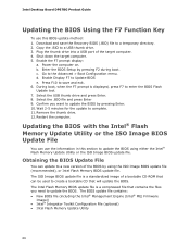
... of the target computer. 4. Wait 2-5 minutes for the update to the Advanced > Boot Configuration menu. Go to complete. 11. Plug the thumb drive into a USB port of a bootable CD-ROM that will update the BIOS. The ISO Image BIOS update file is displayed, press F7 to update the BIOS by... pressing F2 during boot. Intel Desktop Board DP67BG Product Guide Updating the BIOS Using the F7 Function Key To use the information in this BIOS update method: 1. Select the .BIO file and...
... of the target computer. 4. Wait 2-5 minutes for the update to the Advanced > Boot Configuration menu. Go to complete. 11. Plug the thumb drive into a USB port of a bootable CD-ROM that will update the BIOS. The ISO Image BIOS update file is displayed, press F7 to update the BIOS by... pressing F2 during boot. Intel Desktop Board DP67BG Product Guide Updating the BIOS Using the F7 Function Key To use the information in this BIOS update method: 1. Select the .BIO file and...

Product Guide
Page 67
... files can also be extracted locally to your hard drive and copied to the USB device. 3. Updating the BIOS with the Intel Flash Memory Update Utility With the Intel Flash Memory Update Utility you to the Intel Desktop Board DP67BG page on the "BIOS Update" link and then select the the Iflash BIOS ...Update file. CAUTION Do not interrupt the process or the system may not function properly. 1. Configure the BIOS or use the F10 option during POST to boot to a bootable USB flash drive ...
... files can also be extracted locally to your hard drive and copied to the USB device. 3. Updating the BIOS with the Intel Flash Memory Update Utility With the Intel Flash Memory Update Utility you to the Intel Desktop Board DP67BG page on the "BIOS Update" link and then select the the Iflash BIOS ...Update file. CAUTION Do not interrupt the process or the system may not function properly. 1. Configure the BIOS or use the F10 option during POST to boot to a bootable USB flash drive ...
Product Guide
Page 70
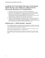
.../916196/en-us for Microsoft Windows XP Installation) 1. Intel Desktop Board DP67BG Product Guide Loading the Intel Rapid Storage Technology RAID Drivers and Software (Required for information on supported USB floppy disk drives. Refer to a RAID setup. 70 Install the Intel Rapid Storage Console software via the Intel Express Installer CD included with your Desktop Board...
.../916196/en-us for Microsoft Windows XP Installation) 1. Intel Desktop Board DP67BG Product Guide Loading the Intel Rapid Storage Technology RAID Drivers and Software (Required for information on supported USB floppy disk drives. Refer to a RAID setup. 70 Install the Intel Rapid Storage Console software via the Intel Express Installer CD included with your Desktop Board...
Product Guide
Page 74
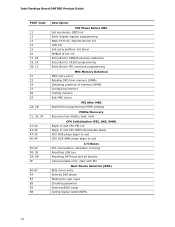
Intel Desktop Board DP67BG Product Guide POST Code 11 12 13 14 15 16 17, 18 19, 1A 1B, 1C 21 23 24 27 28 29 2A, 2B 31, ... CPU SMM init/relocate bases CPU DXE phase begin to end CPU DXE SMM phase begin to end I/O Buses PCI enumeration, allocation, hot plug Resetting USB bus Resetting SATA bus and all devices Unrecoverable error, start with PIC Boot Device Selection (BDS) BDS driver entry Entered DXE phase Waiting for user...
Intel Desktop Board DP67BG Product Guide POST Code 11 12 13 14 15 16 17, 18 19, 1A 1B, 1C 21 23 24 27 28 29 2A, 2B 31, ... CPU SMM init/relocate bases CPU DXE phase begin to end CPU DXE SMM phase begin to end I/O Buses PCI enumeration, allocation, hot plug Resetting USB bus Resetting SATA bus and all devices Unrecoverable error, start with PIC Boot Device Selection (BDS) BDS driver entry Entered DXE phase Waiting for user...
Product Specification
Page 5
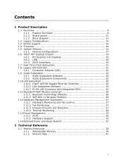
... 9 1.1.2 Board Layout 11 1.1.3 Block Diagram 13 1.2 Legacy Considerations 14 1.3 Online Support 14 1.4 Processor 14 1.5 System Memory 15 1.5.1 Memory Configurations 17 1.6 Intel® P67 Express Chipset 19 1.6.1 PCI Express x16 Graphics 19 1.6.2 USB 19 1.6.3 SATA Interfaces 19 1.7 Real-Time Clock Subsystem 21 1.8 Legacy I/O Controller 21 1.8.1 Consumer Infrared (CIR 21 1.9 Audio Subsystem 22 1.9.1 Audio...
... 9 1.1.2 Board Layout 11 1.1.3 Block Diagram 13 1.2 Legacy Considerations 14 1.3 Online Support 14 1.4 Processor 14 1.5 System Memory 15 1.5.1 Memory Configurations 17 1.6 Intel® P67 Express Chipset 19 1.6.1 PCI Express x16 Graphics 19 1.6.2 USB 19 1.6.3 SATA Interfaces 19 1.7 Real-Time Clock Subsystem 21 1.8 Legacy I/O Controller 21 1.8.1 Consumer Infrared (CIR 21 1.9 Audio Subsystem 22 1.9.1 Audio...
Product Specification
Page 6
Intel Desktop Board DP67BG Technical Product Specification 2.2 Connectors and Headers 41 2.2.1 Back Panel Connectors 42 2.2.2 Component-side Connectors and Headers 43 2.3 Jumper Block 52 2.4 Mechanical ...3 Overview of BIOS Features 3.1 Introduction 61 3.2 BIOS Flash Memory Organization 62 3.3 Resource Configuration 62 3.3.1 PCI Autoconfiguration 62 3.4 System Management BIOS (SMBIOS 63 3.5 Legacy USB Support 63 3.6 BIOS Updates 64 3.6.1 Language Support 64 3.6.2 Custom Splash Screen 65 3.7 BIOS Recovery 65 3.8 Boot Options 66 3.8.1 Optical Drive Boot 66 3.8.2 Network ...
Intel Desktop Board DP67BG Technical Product Specification 2.2 Connectors and Headers 41 2.2.1 Back Panel Connectors 42 2.2.2 Component-side Connectors and Headers 43 2.3 Jumper Block 52 2.4 Mechanical ...3 Overview of BIOS Features 3.1 Introduction 61 3.2 BIOS Flash Memory Organization 62 3.3 Resource Configuration 62 3.3.1 PCI Autoconfiguration 62 3.4 System Management BIOS (SMBIOS 63 3.5 Legacy USB Support 63 3.6 BIOS Updates 64 3.6.1 Language Support 64 3.6.2 Custom Splash Screen 65 3.7 BIOS Recovery 65 3.8 Boot Options 66 3.8.1 Optical Drive Boot 66 3.8.2 Network ...
Product Specification
Page 7
... Figures 1. Back Panel Connectors 42 98H 278H 11. Diagnostic LEDs 36 13H 293H 10. Supported Memory Configurations 16 107H 287H 4. Connection Diagram for Front Panel USB Headers 51 10H 281H 14.
... Figures 1. Back Panel Connectors 42 98H 278H 11. Diagnostic LEDs 36 13H 293H 10. Supported Memory Configurations 16 107H 287H 4. Connection Diagram for Front Panel USB Headers 51 10H 281H 14.

