
Product Guide
Page 5
Contents 1 Desktop Board Features Supported Operating Systems 11 Desktop Board Components 12 Processor ...14 Main Memory...15 Intel® P67 Express Chipset 16 Audio Subsystem 16 LAN Subsystem 17 USB Support ...18 Serial ATA Support 18 Legacy I/O ...18 ... Speaker...27 Battery ...27 Real-Time Clock 27 2 Installing and Replacing Desktop Board Components Before You Begin 29 Installation Precautions 30 Prevent Power Supply Overload 30 Observe Safety and Regulatory Requirements 30 Installing the I/O Shield 31 Installing and Removing the Desktop Board 32 Installing and Removing a Processor...
Contents 1 Desktop Board Features Supported Operating Systems 11 Desktop Board Components 12 Processor ...14 Main Memory...15 Intel® P67 Express Chipset 16 Audio Subsystem 16 LAN Subsystem 17 USB Support ...18 Serial ATA Support 18 Legacy I/O ...18 ... Speaker...27 Battery ...27 Real-Time Clock 27 2 Installing and Replacing Desktop Board Components Before You Begin 29 Installation Precautions 30 Prevent Power Supply Overload 30 Observe Safety and Regulatory Requirements 30 Installing the I/O Shield 31 Installing and Removing the Desktop Board 32 Installing and Removing a Processor...

Product Guide
Page 6
Intel Desktop Board DP67BG Product Guide Installing a Processor 33 Installing the Processor Fan Heat Sink 37 Connecting the Processor Fan Heat Sink Cable 37 Removing the Processor 37 Installing ... 48 IEEE 1394a Header 48 Front Panel Intel HD Audio Header 48 Alternate Front Panel Power LED Header 49 Consumer IR (CIR) Headers 49 USB 2.0 Headers 50 Front Panel Header 51 Chassis Intrusion Header 51 Connecting to the Audio System 52 Connecting Chassis Fan and Power Supply Cables 53 Connecting Chassis Fan Cables 53...
Intel Desktop Board DP67BG Product Guide Installing a Processor 33 Installing the Processor Fan Heat Sink 37 Connecting the Processor Fan Heat Sink Cable 37 Removing the Processor 37 Installing ... 48 IEEE 1394a Header 48 Front Panel Intel HD Audio Header 48 Alternate Front Panel Power LED Header 49 Consumer IR (CIR) Headers 49 USB 2.0 Headers 50 Front Panel Header 51 Chassis Intrusion Header 51 Connecting to the Audio System 52 Connecting Chassis Fan and Power Supply Cables 53 Connecting Chassis Fan Cables 53...
Product Guide
Page 8
...Names 48 9. Alternate Front Panel Power LED Header Signal Names 49 10. LAN Connector LEDs 17 5. Diagnostic LEDs 26 6. Jumper Settings for the BIOS Setup Program Modes 56 16. BIOS Error Messages 72 19. Intel Desktop Board DP67BG Product Guide 25. Installing the... Regulations 83 22. Chassis Intrusion Header Signal Names 51 15. Connecting Power Supply Cables 54 28. Intel Desktop Board DP67BG Components 13 3. Safety Standards 77 21. Removing the Battery 62 30. Intel Desktop Board DP67BG China RoHS Material Self Declaration Table 82 Tables 1. Back Panel CIR ...
...Names 48 9. Alternate Front Panel Power LED Header Signal Names 49 10. LAN Connector LEDs 17 5. Diagnostic LEDs 26 6. Jumper Settings for the BIOS Setup Program Modes 56 16. BIOS Error Messages 72 19. Intel Desktop Board DP67BG Product Guide 25. Installing the... Regulations 83 22. Chassis Intrusion Header Signal Names 51 15. Connecting Power Supply Cables 54 28. Intel Desktop Board DP67BG Components 13 3. Safety Standards 77 21. Removing the Battery 62 30. Intel Desktop Board DP67BG China RoHS Material Self Declaration Table 82 Tables 1. Back Panel CIR ...
Product Guide
Page 14
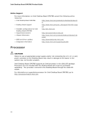
.../support?iid=hdr+supp ort • Available configurations for Intel Desktop Board DP67BG, go /buildit Processor CAUTION Failure to use an appropriate power supply and/or not connecting the 12 V (2 x 4 pin) power connector to the Desktop Board may result in the LGA1155 package. Intel Desktop Board DP67BG Product Guide Online Support For more information on supported processors...
.../support?iid=hdr+supp ort • Available configurations for Intel Desktop Board DP67BG, go /buildit Processor CAUTION Failure to use an appropriate power supply and/or not connecting the 12 V (2 x 4 pin) power connector to the Desktop Board may result in the LGA1155 package. Intel Desktop Board DP67BG Product Guide Online Support For more information on supported processors...
Product Guide
Page 20
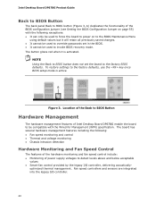
...Location of the Back to BIOS Button Hardware Management The hardware management features of Intel Desktop Board DP67BG enable the board to be used to override passwords set the board to the factory BIOS defaults. Intel Desktop Board DP67BG Product Guide Back to BIOS Button The back panel Back to BIOS button (Figure...8226; Chassis intrusion detection Hardware Monitoring and Fan Speed Control The features of the hardware monitoring and fan speed control include: • Monitoring of power supply voltages to the factory defaults, use the key once BIOS setup mode is activated. Figure 3.
...Location of the Back to BIOS Button Hardware Management The hardware management features of Intel Desktop Board DP67BG enable the board to be used to override passwords set the board to the factory BIOS defaults. Intel Desktop Board DP67BG Product Guide Back to BIOS Button The back panel Back to BIOS button (Figure...8226; Chassis intrusion detection Hardware Monitoring and Fan Speed Control The features of the hardware monitoring and fan speed control include: • Monitoring of power supply voltages to the factory defaults, use the key once BIOS setup mode is activated. Figure 3.
Product Guide
Page 21
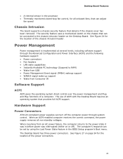
... (either on page 54 for the location of a computer. When an ACPI-enabled computer receives the correct command, the power supply removes all onboard fans, that provides full ACPI support. The computer's response can adjust fan speed Chassis Intrusion The board ... Software Support ACPI ACPI gives the operating system direct control over the power management and Plug and Play functions of the power connectors. 21 Hardware Support Power Connectors ATX12V-compliant power supplies can be set by using the Last Power State feature in the BIOS Setup program's Boot menu. Desktop Board ...
... (either on page 54 for the location of a computer. When an ACPI-enabled computer receives the correct command, the power supply removes all onboard fans, that provides full ACPI support. The computer's response can adjust fan speed Chassis Intrusion The board ... Software Support ACPI ACPI gives the operating system direct control over the power management and Plug and Play functions of the power connectors. 21 Hardware Support Power Connectors ATX12V-compliant power supplies can be set by using the Last Power State feature in the BIOS Setup program's Boot menu. Desktop Board ...

Product Guide
Page 22
...The LAN subsystem monitors network traffic and upon detecting a Magic Packet* frame, it asserts a wake-up of the computer through a network. Power supplies used with this Desktop Board must be capable of delivering adequate +5 V standby current. The Desktop Board has a 4-pin processor fan header and...current necessary to support multiple wake events from the PCI and/or USB buses exceeds power supply capacity, the Desktop Board may lose register settings stored in memory. 22 Intel Desktop Board DP67BG Product Guide Fan Headers The function/operation of the fans is wired to a tachometer...
...The LAN subsystem monitors network traffic and upon detecting a Magic Packet* frame, it asserts a wake-up of the computer through a network. Power supplies used with this Desktop Board must be capable of delivering adequate +5 V standby current. The Desktop Board has a 4-pin processor fan header and...current necessary to support multiple wake events from the PCI and/or USB buses exceeds power supply capacity, the Desktop Board may lose register settings stored in memory. 22 Intel Desktop Board DP67BG Product Guide Fan Headers The function/operation of the fans is wired to a tachometer...

Product Guide
Page 29
...steps in each procedure in the correct order. • Set up a log to the audio system • Connect chassis fan and power supply cables • Set the BIOS configuration jumper • Clear passwords • Replace the battery • Install the WiFi/BlueTooth Module ...options, and configuration information. • Electrostatic discharge (ESD) can damage components. Some circuitry on the board can continue to disconnect power, telecommunications links, networks, or modems before performing any procedures can provide some ESD protection by wearing an antistatic wrist strap and ...
...steps in each procedure in the correct order. • Set up a log to the audio system • Connect chassis fan and power supply cables • Set the BIOS configuration jumper • Clear passwords • Replace the battery • Install the WiFi/BlueTooth Module ...options, and configuration information. • Electrostatic discharge (ESD) can damage components. Some circuitry on the board can continue to disconnect power, telecommunications links, networks, or modems before performing any procedures can provide some ESD protection by wearing an antistatic wrist strap and ...
Product Guide
Page 30
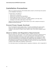
Intel Desktop Board DP67BG Product Guide Installation Precautions When you install and test the Intel Desktop Board, observe all warnings and cautions in this section and the instructions supplied with the chassis and associated modules. To avoid injury, be careful of noncompliance with these instructions... qualified technical personnel. If the instructions for the chassis are inconsistent with regional laws and regulations. To avoid overloading the power supply, make sure that the calculated total current loads of all warnings and cautions that could cause a short circuit Observe all...
Intel Desktop Board DP67BG Product Guide Installation Precautions When you install and test the Intel Desktop Board, observe all warnings and cautions in this section and the instructions supplied with the chassis and associated modules. To avoid injury, be careful of noncompliance with these instructions... qualified technical personnel. If the instructions for the chassis are inconsistent with regional laws and regulations. To avoid overloading the power supply, make sure that the calculated total current loads of all warnings and cautions that could cause a short circuit Observe all...

Product Guide
Page 42
... the socket, and store it in "Before You Begin" on the over-current protection of the power supply, certain Desktop Board components and/or traces may result across the connector pins. Remove the computer's cover. 5. Intel Desktop Board DP67BG Product Guide Removing DIMMs To remove a DIMM, follow these steps: 1. Turn off the computer. 3. Installing...
... the socket, and store it in "Before You Begin" on the over-current protection of the power supply, certain Desktop Board components and/or traces may result across the connector pins. Remove the computer's cover. 5. Intel Desktop Board DP67BG Product Guide Removing DIMMs To remove a DIMM, follow these steps: 1. Turn off the computer. 3. Installing...
Product Guide
Page 53
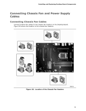
Location of the chassis fan headers. Figure 26 shows the location of the Chassis Fan Headers 53 Figure 26. Installing and Replacing Desktop Board Components Connecting Chassis Fan and Power Supply Cables Connecting Chassis Fan Cables Connect chassis fan cables to the chassis fan headers on the Desktop Board.
Location of the chassis fan headers. Figure 26 shows the location of the Chassis Fan Headers 53 Figure 26. Installing and Replacing Desktop Board Components Connecting Chassis Fan and Power Supply Cables Connecting Chassis Fan Cables Connect chassis fan cables to the chassis fan headers on the Desktop Board.

Product Guide
Page 54
The 2 x 12 pin main power connector (Figure 27, C) is backwards compatible with ATX12V power supplies with 2 x 10 connectors. Intel Desktop Board DP67BG Product Guide Connecting Power Supply Cables Figure 27 shows the location of the power connectors. Connecting Power Supply Cables 54 Figure 27. CAUTION Failure to use an appropriate power supply and/or not connecting the 12 V (Figure 27, A) power connector to the Desktop Board may result in damage to the board or the system may not function properly.
The 2 x 12 pin main power connector (Figure 27, C) is backwards compatible with ATX12V power supplies with 2 x 10 connectors. Intel Desktop Board DP67BG Product Guide Connecting Power Supply Cables Figure 27 shows the location of the power connectors. Connecting Power Supply Cables 54 Figure 27. CAUTION Failure to use an appropriate power supply and/or not connecting the 12 V (Figure 27, A) power connector to the Desktop Board may result in damage to the board or the system may not function properly.
Product Guide
Page 55
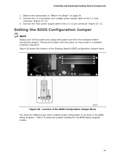
...may result in "Before You Begin" on page 29. 2. Figure 28. Connect the main power supply cable to be done in the BIOS Setup program. Setting the BIOS Configuration Jumper NOTE Always turn off the power and unplug the power cord from the computer before moving the jumper. Table 15 shows the jumper settings... Jumper Block The three-pin BIOS jumper block enables board configuration to the 2 x 12 pin connector (Figure 27, C). Connect the 12 V processor core voltage power supply cable to the 2 x 4 pin connector (Figure 27, A). 3. Installing and Replacing Desktop Board Components 1.
...may result in "Before You Begin" on page 29. 2. Figure 28. Connect the main power supply cable to be done in the BIOS Setup program. Setting the BIOS Configuration Jumper NOTE Always turn off the power and unplug the power cord from the computer before moving the jumper. Table 15 shows the jumper settings... Jumper Block The three-pin BIOS jumper block enables board configuration to the 2 x 12 pin connector (Figure 27, C). Connect the 12 V processor core voltage power supply cable to the 2 x 4 pin connector (Figure 27, A). 3. Installing and Replacing Desktop Board Components 1.

Product Guide
Page 57
Installing and Replacing Desktop Board Components 10. Replace the cover, plug in , the standby current from the AC power source. 11. When the computer is plugged in the computer, and turn on pins 1-2 as shown below a certain level, the BIOS Setup program settings...par une pile de type incorrect. Remove the computer cover. 12. Replacing the Battery A coin-cell battery (CR2032) powers the real-time clock and CMOS memory. Disconnect the computer's power cord from the power supply extends the life of three years. When the voltage drops below . 13. The clock is replaced with 3.3 VSB ...
Installing and Replacing Desktop Board Components 10. Replace the cover, plug in , the standby current from the AC power source. 11. When the computer is plugged in the computer, and turn on pins 1-2 as shown below a certain level, the BIOS Setup program settings...par une pile de type incorrect. Remove the computer cover. 12. Replacing the Battery A coin-cell battery (CR2032) powers the real-time clock and CMOS memory. Disconnect the computer's power cord from the power supply extends the life of three years. When the voltage drops below . 13. The clock is replaced with 3.3 VSB ...
Product Guide
Page 85
...I/O cable shielding and filtering • Mounting, grounding, and bonding requirements • Keying connectors when mating the wrong connectors could be hazardous If the power supply and other modules or peripherals, as applicable, have passed Class B EMC testing and are not Class B EMC compliant before integration, then EMC testing ..., but also other areas. Regulatory Compliance Korea Class B Statement Korea Class B Statement translation: This equipment is for the host chassis, power supply, and other modules: • Product certifications or lack of the newly completed computer. 85
...I/O cable shielding and filtering • Mounting, grounding, and bonding requirements • Keying connectors when mating the wrong connectors could be hazardous If the power supply and other modules or peripherals, as applicable, have passed Class B EMC testing and are not Class B EMC compliant before integration, then EMC testing ..., but also other areas. Regulatory Compliance Korea Class B Statement Korea Class B Statement translation: This equipment is for the host chassis, power supply, and other modules: • Product certifications or lack of the newly completed computer. 85
Product Guide
Page 87
...certain components; such as CSA or cUL signifies compliance with electromagnetic interference (EMI) requirements. In Canada A nationally recognized certification mark such as the power supply, peripheral drives, wiring, and cables; Chassis and Component Certifications Ensure that the chassis and certain components; Wiring and cables must also be UL... also apply depending on product features. are proof of Conformity statement to the European EMC directive, Low Voltage directive (as the power supply, peripheral drives, wiring, and cables; Regulatory Compliance Chassis-
...certain components; such as CSA or cUL signifies compliance with electromagnetic interference (EMI) requirements. In Canada A nationally recognized certification mark such as the power supply, peripheral drives, wiring, and cables; Chassis and Component Certifications Ensure that the chassis and certain components; Wiring and cables must also be UL... also apply depending on product features. are proof of Conformity statement to the European EMC directive, Low Voltage directive (as the power supply, peripheral drives, wiring, and cables; Regulatory Compliance Chassis-

Product Guide
Page 88
... this product guide demonstrates compliance with safety requirements. Intel Desktop Board DP67BG meets the following program requirements in the definition of Energy and the US Environmental Protection Agency have continually revised the ENERGY STAR requirements. The Industry Canada statement on page 84 of an efficient power supply: • Energy Star v5.0, category D • EPEAT...
... this product guide demonstrates compliance with safety requirements. Intel Desktop Board DP67BG meets the following program requirements in the definition of Energy and the US Environmental Protection Agency have continually revised the ENERGY STAR requirements. The Industry Canada statement on page 84 of an efficient power supply: • Energy Star v5.0, category D • EPEAT...
Product Specification
Page 6
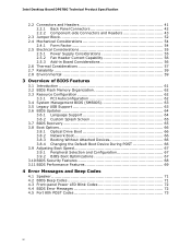
Intel Desktop Board DP67BG Technical Product Specification 2.2 Connectors and Headers 41 2.2.1 Back Panel Connectors 42 2.2.2 Component-side Connectors and Headers 43 2.3 Jumper Block 52 2.4 Mechanical Considerations 54 2.4.1 Form Factor 54 2.5 Electrical Considerations 55 2.5.1 Power Supply Considerations 55 2.5.2 Fan Header Current Capability 56 2.5.3 Add-in Board Considerations 56 2.6 ...Performance Features 69 4 Error Messages and Beep Codes 4.1 Speaker 71 4.2 BIOS Beep Codes 71 4.3 Front-panel Power LED Blink Codes 72 4.4 BIOS Error Messages 72 4.5 Port 80h POST Codes 73 vi
Intel Desktop Board DP67BG Technical Product Specification 2.2 Connectors and Headers 41 2.2.1 Back Panel Connectors 42 2.2.2 Component-side Connectors and Headers 43 2.3 Jumper Block 52 2.4 Mechanical Considerations 54 2.4.1 Form Factor 54 2.5 Electrical Considerations 55 2.5.1 Power Supply Considerations 55 2.5.2 Fan Header Current Capability 56 2.5.3 Add-in Board Considerations 56 2.6 ...Performance Features 69 4 Error Messages and Beep Codes 4.1 Speaker 71 4.2 BIOS Beep Codes 71 4.3 Front-panel Power LED Blink Codes 72 4.4 BIOS Error Messages 72 4.5 Port 80h POST Codes 73 vi
Product Specification
Page 8
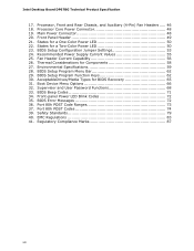
... Setup Program Menu Bar 62 29. Environmental Specifications 59 28. Recommended Power Supply Current Values 55 25. Safety Standards 79 40. Processor Core Power Connector 48 19. Intel Desktop Board DP67BG Technical Product Specification 17. BIOS Setup Configuration Jumper Settings 53 24. Front-panel Power LED Blink Codes 72 35. Supervisor and User Password Functions 68...
... Setup Program Menu Bar 62 29. Environmental Specifications 59 28. Recommended Power Supply Current Values 55 25. Safety Standards 79 40. Processor Core Power Connector 48 19. Intel Desktop Board DP67BG Technical Product Specification 17. BIOS Setup Configuration Jumper Settings 53 24. Front-panel Power LED Blink Codes 72 35. Supervisor and User Password Functions 68...

Product Specification
Page 10
Intel Desktop Board DP67BG Technical Product Specification Table 1. Feature Summary (continued) Instantly Available PC Technology... PCI Express, LAN, front panel, CIR, and USB ports Gigabit (10/100/1000 Mbits/s) LAN subsystem using the Intel® 82579V Gigabit Ethernet Controller • Two PCI Express 2.0 x16 • Three PCI Express x1 bus add-in...8226; Hardware monitoring and fan control through the Nuvoton I/O controller • Voltage sense to detect out of range power supply voltages • Thermal sense to detect out of range thermal values • Four fan headers using PWM control...
Intel Desktop Board DP67BG Technical Product Specification Table 1. Feature Summary (continued) Instantly Available PC Technology... PCI Express, LAN, front panel, CIR, and USB ports Gigabit (10/100/1000 Mbits/s) LAN subsystem using the Intel® 82579V Gigabit Ethernet Controller • Two PCI Express 2.0 x16 • Three PCI Express x1 bus add-in...8226; Hardware monitoring and fan control through the Nuvoton I/O controller • Voltage sense to detect out of range power supply voltages • Thermal sense to detect out of range thermal values • Four fan headers using PWM control...


