
Product Guide
Page 5
Contents 1 Desktop Board Features Supported Operating Systems 11 Desktop Board Components 12 Processor ...14 Main Memory...15 Intel® P67 Express Chipset 16 Audio Subsystem 16 LAN Subsystem 17 USB Support ...18 Serial ATA Support 18 Legacy I/O ...18 ...26 Speaker...27 Battery ...27 Real-Time Clock 27 2 Installing and Replacing Desktop Board Components Before You Begin 29 Installation Precautions 30 Prevent Power Supply Overload 30 Observe Safety and Regulatory Requirements 30 Installing the I/O Shield 31 Installing and Removing the Desktop Board 32 Installing and Removing ...
Contents 1 Desktop Board Features Supported Operating Systems 11 Desktop Board Components 12 Processor ...14 Main Memory...15 Intel® P67 Express Chipset 16 Audio Subsystem 16 LAN Subsystem 17 USB Support ...18 Serial ATA Support 18 Legacy I/O ...18 ...26 Speaker...27 Battery ...27 Real-Time Clock 27 2 Installing and Replacing Desktop Board Components Before You Begin 29 Installation Precautions 30 Prevent Power Supply Overload 30 Observe Safety and Regulatory Requirements 30 Installing the I/O Shield 31 Installing and Removing the Desktop Board 32 Installing and Removing ...

Product Guide
Page 6
Intel Desktop Board DP67BG Product Guide Installing a Processor 33 Installing the Processor Fan Heat Sink...46 Connecting to the Internal Headers 47 S/PDIF Header 48 IEEE 1394a Header 48 Front Panel Intel HD Audio Header 48 Alternate Front Panel Power LED Header 49 Consumer IR (CIR) Headers 49 USB 2.0 Headers 50 Front Panel Header...Chassis Intrusion Header 51 Connecting to the Audio System 52 Connecting Chassis Fan and Power Supply Cables 53 Connecting Chassis Fan Cables 53 Connecting Power Supply Cables 54 Setting the BIOS Configuration Jumper 55 Clearing Passwords 56 Replacing the ...
Intel Desktop Board DP67BG Product Guide Installing a Processor 33 Installing the Processor Fan Heat Sink...46 Connecting to the Internal Headers 47 S/PDIF Header 48 IEEE 1394a Header 48 Front Panel Intel HD Audio Header 48 Alternate Front Panel Power LED Header 49 Consumer IR (CIR) Headers 49 USB 2.0 Headers 50 Front Panel Header...Chassis Intrusion Header 51 Connecting to the Audio System 52 Connecting Chassis Fan and Power Supply Cables 53 Connecting Chassis Fan Cables 53 Connecting Power Supply Cables 54 Setting the BIOS Configuration Jumper 55 Clearing Passwords 56 Replacing the ...
Product Guide
Page 7
...33 10. Removing a PCI Express x16 Graphics Card 44 22. LAN Connector LEDs 17 3. Intel Desktop Board DP67BG Mounting Screw Hole Locations 32 9. Connecting the Processor Fan Heat Sink Power Cable to BIOS Button 20 4. Example Dual Channel Memory Configuration with Two DIMMs 38 16. ...47 vii and Component-Level Certifications 87 Chassis and Component Certifications 87 ENERGY STAR*, e-Standby, and ErP Compliance 88 Figures 1. Intel Desktop Board DP67BG Components 12 2. Location of the Back to the Processor Fan Header 37 15. Install the Processor 35 13. Secure the ...
...33 10. Removing a PCI Express x16 Graphics Card 44 22. LAN Connector LEDs 17 3. Intel Desktop Board DP67BG Mounting Screw Hole Locations 32 9. Connecting the Processor Fan Heat Sink Power Cable to BIOS Button 20 4. Example Dual Channel Memory Configuration with Two DIMMs 38 16. ...47 vii and Component-Level Certifications 87 Chassis and Component Certifications 87 ENERGY STAR*, e-Standby, and ErP Compliance 88 Figures 1. Intel Desktop Board DP67BG Components 12 2. Location of the Back to the Processor Fan Header 37 15. Install the Processor 35 13. Secure the ...
Product Guide
Page 8
...Header Signal Names 50 13. Jumper Settings for the BIOS Setup Program Modes 56 16. Front-panel Power LED Blink Codes 71 18. Location of the Chassis Fan Headers 53 27. Intel Desktop Board DP67BG Components 13 3. IEEE 1394a Header Signal Names 48 8. BIOS Error Messages 72 19. Port 80h... POST Codes 73 20. Installing the WiFi/Bluetooth Module 64 31. Front Panel Header Signal Names 51 14. Intel Desktop Board DP67BG China RoHS Material Self Declaration Table 82 Tables 1. Feature Summary 9 2. BIOS Beep Codes 71 17. EMC Regulations 83 22. Location ...
...Header Signal Names 50 13. Jumper Settings for the BIOS Setup Program Modes 56 16. Front-panel Power LED Blink Codes 71 18. Location of the Chassis Fan Headers 53 27. Intel Desktop Board DP67BG Components 13 3. IEEE 1394a Header Signal Names 48 8. BIOS Error Messages 72 19. Port 80h... POST Codes 73 20. Installing the WiFi/Bluetooth Module 64 31. Front Panel Header Signal Names 51 14. Intel Desktop Board DP67BG China RoHS Material Self Declaration Table 82 Tables 1. Feature Summary 9 2. BIOS Beep Codes 71 17. EMC Regulations 83 22. Location ...
Product Guide
Page 10
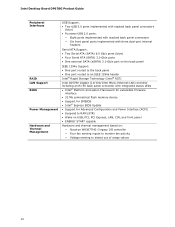
Intel Desktop Board DP67BG Product Guide Peripheral Interfaces RAID LAN Support BIOS Power Management Hardware and Thermal Management USB Support: • Two USB 3.0 ports implemented with stacked back panel connectors (blue) • Fourteen USB 2.0 ports: &#...; Platform Innovation Framework for extensible firmware interface • 32 Mb symmetrical flash memory device • Support for SMBIOS • Intel® Express BIOS Update • Support for Advanced Configuration and Power Interface (ACPI) • Suspend to RAM (STR) • Wake on USB, PCI, PCI Express, LAN, CIR, and front ...
Intel Desktop Board DP67BG Product Guide Peripheral Interfaces RAID LAN Support BIOS Power Management Hardware and Thermal Management USB Support: • Two USB 3.0 ports implemented with stacked back panel connectors (blue) • Fourteen USB 2.0 ports: &#...; Platform Innovation Framework for extensible firmware interface • 32 Mb symmetrical flash memory device • Support for SMBIOS • Intel® Express BIOS Update • Support for Advanced Configuration and Power Interface (ACPI) • Suspend to RAM (STR) • Wake on USB, PCI, PCI Express, LAN, CIR, and front ...
Product Guide
Page 13
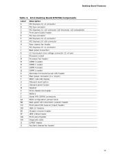
... 1 socket DIMM 4 socket DIMM 2 socket Alternate front panel power LED header Main power connector (2 x 12 pin) POST code LED display Onboard reset button Onboard power button Speaker Front chassis fan header Battery Serial ATA (SATA) ...connectors BIOS configuration jumper block Back panel CIR transmitter (output) header Front panel CIR receiver (input) header USB 2.0 headers Chassis intrusion header IEEE 1394a header Front panel header Diagnostic LEDs S/PDIF header Auxiliary chassis fan header 13 Intel Desktop Board DP67BG...
... 1 socket DIMM 4 socket DIMM 2 socket Alternate front panel power LED header Main power connector (2 x 12 pin) POST code LED display Onboard reset button Onboard power button Speaker Front chassis fan header Battery Serial ATA (SATA) ...connectors BIOS configuration jumper block Back panel CIR transmitter (output) header Front panel CIR receiver (input) header USB 2.0 headers Chassis intrusion header IEEE 1394a header Front panel header Diagnostic LEDs S/PDIF header Auxiliary chassis fan header 13 Intel Desktop Board DP67BG...
Product Guide
Page 14
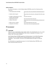
....intel.com. 14 For information on Intel Desktop Board DP67BG consult the following online resources: • Intel Desktop Board DP67BG http://www.intel.com/products/motherboard/index.ht m • Desktop Board Support http://www.intel.com/p/en_US/support?iid=hdr+supp ort • Available configurations for Intel Desktop Board DP67BG, go /buildit Processor CAUTION Failure to use an appropriate power...
....intel.com. 14 For information on Intel Desktop Board DP67BG consult the following online resources: • Intel Desktop Board DP67BG http://www.intel.com/products/motherboard/index.ht m • Desktop Board Support http://www.intel.com/p/en_US/support?iid=hdr+supp ort • Available configurations for Intel Desktop Board DP67BG, go /buildit Processor CAUTION Failure to use an appropriate power...

Product Guide
Page 15
... NOTE To be fully compliant with all applicable Intel ® SDRAM memory specifications, the board should be populated with a voltage rating higher than 4 GB because of the memory used by add-in two channels • 2133 MHz to this effect on the screen at power up. The Desktop Board supports the following...
... NOTE To be fully compliant with all applicable Intel ® SDRAM memory specifications, the board should be populated with a voltage rating higher than 4 GB because of the memory used by add-in two channels • 2133 MHz to this effect on the screen at power up. The Desktop Board supports the following...

Product Guide
Page 17
... LAN subsystem includes: • Intel P67 PCH • Intel 82579V Gigabit (10/100/1000 Mb/s) Ethernet LAN controller • RJ-45 LAN connector with integrated status LEDs The subsystem features: • CSMA/CD protocol engine • LAN connect interface between PCH and the LAN controller • PCI bus power management Two LEDs are...
... LAN subsystem includes: • Intel P67 PCH • Intel 82579V Gigabit (10/100/1000 Mb/s) Ethernet LAN controller • RJ-45 LAN connector with integrated status LEDs The subsystem features: • CSMA/CD protocol engine • LAN connect interface between PCH and the LAN controller • PCI bus power management Two LEDs are...
Product Guide
Page 18
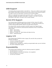
... that provides the following I/O features: • Consumer Infrared (CIR) support • Low pin count (LPC) interface • Intelligent power management, including a programmable wake up event interface • PCI power management support Expandability Intel Desktop Board DP67BG provides the following RAID (Redundant Array of Independent Drives) levels: • RAID 0 - There are backward compatible with USB...
... that provides the following I/O features: • Consumer Infrared (CIR) support • Low pin count (LPC) interface • Intelligent power management, including a programmable wake up event interface • PCI power management support Expandability Intel Desktop Board DP67BG provides the following RAID (Redundant Array of Independent Drives) levels: • RAID 0 - There are backward compatible with USB...
Product Guide
Page 19
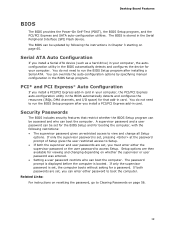
... password, go to run the BIOS Setup program after you must enter either password to access Setup. Desktop Board Features BIOS The BIOS provides the Power-On Self-Test (POST), the BIOS Setup program, and the PCI/PCI Express and SATA auto-configuration utilities. You do not need to view and...
... password, go to run the BIOS Setup program after you must enter either password to access Setup. Desktop Board Features BIOS The BIOS provides the Power-On Self-Test (POST), the BIOS Setup program, and the PCI/PCI Express and SATA auto-configuration utilities. You do not need to view and...
Product Guide
Page 20
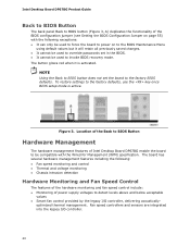
... changes. • It cannot be used to force the board to power on to the BIOS Maintenance Menu using default values but it is active. Location of the Back to BIOS Button Hardware Management The hardware management features of Intel Desktop Board DP67BG enable the board to be compatible with the following : •...
... changes. • It cannot be used to force the board to power on to the BIOS Maintenance Menu using default values but it is active. Location of the Back to BIOS Button Hardware Management The hardware management features of Intel Desktop Board DP67BG enable the board to be compatible with the following : •...
Product Guide
Page 21
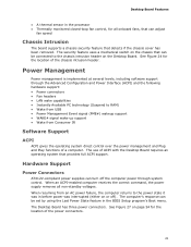
... IR Software Support ACPI ACPI gives the operating system direct control over the power management and Plug and Play functions of the power connectors. 21 Hardware Support Power Connectors ATX12V-compliant power supplies can adjust fan speed Chassis Intrusion The board supports a chassis security feature... in the BIOS Setup program's Boot menu. See Figure 27 on the Desktop Board. The Desktop Board has three power connectors. Power Management Power management is implemented at several levels, including software support through system control. The use of the chassis intrusion header. ...
... IR Software Support ACPI ACPI gives the operating system direct control over the power management and Plug and Play functions of the power connectors. 21 Hardware Support Power Connectors ATX12V-compliant power supplies can adjust fan speed Chassis Intrusion The board supports a chassis security feature... in the BIOS Setup program's Boot menu. See Figure 27 on the Desktop Board. The Desktop Board has three power connectors. Power Management Power management is implemented at several levels, including software support through system control. The use of the chassis intrusion header. ...

Product Guide
Page 22
...this Desktop Board must be capable of delivering adequate +5 V standby current. LAN wakeup capabilities enable remote wake-up signal that can damage the power supply. The LAN subsystem monitors network traffic and upon detecting a Magic Packet* frame, it asserts a wake-up of the computer through a ...network. The Desktop Board has a 4-pin processor fan header and three 4-pin chassis fan headers. Intel Desktop Board DP67BG Product Guide Fan Headers The function/operation of the fans is as follows: • The fans are on when the computer is in ...
...this Desktop Board must be capable of delivering adequate +5 V standby current. LAN wakeup capabilities enable remote wake-up signal that can damage the power supply. The LAN subsystem monitors network traffic and upon detecting a Magic Packet* frame, it asserts a wake-up of the computer through a ...network. The Desktop Board has a 4-pin processor fan header and three 4-pin chassis fan headers. Intel Desktop Board DP67BG Product Guide Fan Headers The function/operation of the fans is as follows: • The fans are on when the computer is in ...

Product Guide
Page 23
...the computer. Wake from Consumer IR Consumer IR device activity wakes the computer from an ACPI S1, S3, S4, or S5 state. While in power management and can participate in the S3 sleep state, the computer will appear to enter the ACPI S3 (Suspend-toRAM) sleep state. The Desktop ...Board supports the PCI Bus Power Management Interface Specification. Desktop Board Features Instantly Available PC technology enables the board to be used to its last known awake state. WAKE# Signal ...
...the computer. Wake from Consumer IR Consumer IR device activity wakes the computer from an ACPI S1, S3, S4, or S5 state. While in power management and can participate in the S3 sleep state, the computer will appear to enter the ACPI S3 (Suspend-toRAM) sleep state. The Desktop ...Board supports the PCI Bus Power Management Interface Specification. Desktop Board Features Instantly Available PC technology enables the board to be used to its last known awake state. WAKE# Signal ...
Product Guide
Page 24
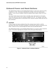
... attached devices. Failure to do so could damage the board and any devices connected to reset the board. Figure 4. Intel Desktop Board DP67BG Product Guide Onboard Power and Reset Buttons The lighted Power button on the Desktop Board (Figure 4, B) can be used to be used to the board. To turn the... computer on or off. CAUTION If the AC power has been switched off and the onboard power button is the case ...
... attached devices. Failure to do so could damage the board and any devices connected to reset the board. Figure 4. Intel Desktop Board DP67BG Product Guide Onboard Power and Reset Buttons The lighted Power button on the Desktop Board (Figure 4, B) can be used to be used to the board. To turn the... computer on or off. CAUTION If the AC power has been switched off and the onboard power button is the case ...

Product Guide
Page 26
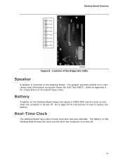
...when the processor initialization activity starts. Just before BIOS transfers control to the operating system, this LED will remain on . 26 Intel Desktop Board DP67BG Product Guide Diagnostic LEDs The Desktop Board provides eight LEDs that allow you to monitor the board's progress through the BIOS... Power-on , all the LEDs are off. Table 5. This LED will flash when the option ROM activity starts. At initial power on Self-Test (see Figure...
...when the processor initialization activity starts. Just before BIOS transfers control to the operating system, this LED will remain on . 26 Intel Desktop Board DP67BG Product Guide Diagnostic LEDs The Desktop Board provides eight LEDs that allow you to monitor the board's progress through the BIOS... Power-on , all the LEDs are off. Table 5. This LED will flash when the option ROM activity starts. At initial power on Self-Test (see Figure...
Product Guide
Page 27
...'s beep codes. Desktop Board Features Figure 6. Location of -day clock and 100-year calendar. The speaker provides audible error code (beep code) information during the Power-On Self-Test (POST).
...'s beep codes. Desktop Board Features Figure 6. Location of -day clock and 100-year calendar. The speaker provides audible error code (beep code) information during the Power-On Self-Test (POST).

Product Guide
Page 29
... an antistatic wrist strap and attaching it to a metal part of the procedures described in this chapter. Disconnect the computer from its power source and from any telecommunications links, networks, or modems before you open the computer or perform any of the computer chassis. 29 ...8226; Connect the Serial ATA cables • Connect to the internal headers • Connect to the audio system • Connect chassis fan and power supply cables • Set the BIOS configuration jumper • Clear passwords • Replace the battery • Install the WiFi/BlueTooth Module Before You...
... an antistatic wrist strap and attaching it to a metal part of the procedures described in this chapter. Disconnect the computer from its power source and from any telecommunications links, networks, or modems before you open the computer or perform any of the computer chassis. 29 ...8226; Connect the Serial ATA cables • Connect to the internal headers • Connect to the audio system • Connect chassis fan and power supply cables • Set the BIOS configuration jumper • Clear passwords • Replace the battery • Install the WiFi/BlueTooth Module Before You...
Product Guide
Page 30
... each of noncompliance with regional laws and regulations. Prevent Power Supply Overload Do not overload the power supply output. If the instructions for associated modules, contact the supplier to find out how you to refer computer servicing to Appendix B. 30 Intel Desktop Board DP67BG Product Guide Installation Precautions When you install and test the...
... each of noncompliance with regional laws and regulations. Prevent Power Supply Overload Do not overload the power supply output. If the instructions for associated modules, contact the supplier to find out how you to refer computer servicing to Appendix B. 30 Intel Desktop Board DP67BG Product Guide Installation Precautions When you install and test the...


