
Product Guide
Page 7
... 23. Installing Linked PCI Express Graphics Cards 46 26. Contents A Error Messages and Indicators BIOS Error Codes 71 BIOS Error Messages 72 Port 80h POST Codes 73 B Regulatory Compliance Safety Standards 77 Place Battery Marking 77 European Union Declaration of Conformity Statement 78 ...Memory Configuration with Three DIMMs 40 21. Unlatch the Socket Lever 33 11. Connecting the Serial ATA Cables 47 27. Intel Desktop Board DP55WG Components 12 2. Location of Hazardous Substances (RoHS 83 EU RoHS 83 China RoHS 84 EMC Regulations 86 Ensure Electromagnetic Compatibility ...
... 23. Installing Linked PCI Express Graphics Cards 46 26. Contents A Error Messages and Indicators BIOS Error Codes 71 BIOS Error Messages 72 Port 80h POST Codes 73 B Regulatory Compliance Safety Standards 77 Place Battery Marking 77 European Union Declaration of Conformity Statement 78 ...Memory Configuration with Three DIMMs 40 21. Unlatch the Socket Lever 33 11. Connecting the Serial ATA Cables 47 27. Intel Desktop Board DP55WG Components 12 2. Location of Hazardous Substances (RoHS 83 EU RoHS 83 China RoHS 84 EMC Regulations 86 Ensure Electromagnetic Compatibility ...

Product Guide
Page 8
...Back Panel Audio Connectors 53 29. Location of the POST Code LED Display 73 34. LAN Connector LEDs 17 4. USB 2.0 Header Signal Names 51 11. China RoHS Environmentally Friendly Use Period Mark 84 21. Intel Desktop Board DP55WG China RoHS Material Self Declaration Table 85 Tables 1....LED Header Signal Names 51 10. Port 80h POST Codes 74 18. Connecting Power Supply Cables 55 31. Front Panel CIR Receiver (Input) Header Signal Names 50 7. BIOS Beep Codes 71 15. Removing the Battery 63 33. Intel Desktop Board DP55WG Components 13 3. Front Panel Header Signal Names ...
...Back Panel Audio Connectors 53 29. Location of the POST Code LED Display 73 34. LAN Connector LEDs 17 4. USB 2.0 Header Signal Names 51 11. China RoHS Environmentally Friendly Use Period Mark 84 21. Intel Desktop Board DP55WG China RoHS Material Self Declaration Table 85 Tables 1....LED Header Signal Names 51 10. Port 80h POST Codes 74 18. Connecting Power Supply Cables 55 31. Front Panel CIR Receiver (Input) Header Signal Names 50 7. BIOS Beep Codes 71 15. Removing the Battery 63 33. Intel Desktop Board DP55WG Components 13 3. Front Panel Header Signal Names ...
Product Guide
Page 13
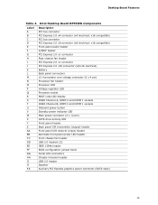
Desktop Board Features Table 2. Intel Desktop Board DP55WG Components Label A B C D E F G H I J K L M N O P Q R S T U V W X Y Z AA BB CC DD EE FF GG HH II JJ KK Description PCI bus connector PCI Express 2.0 x4 connector (x4 electrical...header PCI Express 2.0 x1 connector PCI Express 2.0 x16 connector (x8/x16 electrical) Battery Back panel connectors 12 V processor core voltage connector (2 x 4 pin) Processor fan header Processor LED Voltage regulator LED Processor socket POST code LED display DDR3 Channel A, DIMM 0 and DIMM 1 sockets DDR3 Channel B, DIMM 0 and DIMM 1 sockets Onboard power...
Desktop Board Features Table 2. Intel Desktop Board DP55WG Components Label A B C D E F G H I J K L M N O P Q R S T U V W X Y Z AA BB CC DD EE FF GG HH II JJ KK Description PCI bus connector PCI Express 2.0 x4 connector (x4 electrical...header PCI Express 2.0 x1 connector PCI Express 2.0 x16 connector (x8/x16 electrical) Battery Back panel connectors 12 V processor core voltage connector (2 x 4 pin) Processor fan header Processor LED Voltage regulator LED Processor socket POST code LED display DDR3 Channel A, DIMM 0 and DIMM 1 sockets DDR3 Channel B, DIMM 0 and DIMM 1 sockets Onboard power...

Product Guide
Page 28
... code (beep code) information during the Power-On Self-Test (POST). Real-Time Clock The Desktop Board has a time-of the board's beep codes. Refer to Appendix A for instructions on the Desktop Board. The battery on the Desktop Board keeps the values in CMOS RAM and the clock current when the computer is turned off . 28 Intel Desktop Board DP55WG...
... code (beep code) information during the Power-On Self-Test (POST). Real-Time Clock The Desktop Board has a time-of the board's beep codes. Refer to Appendix A for instructions on the Desktop Board. The battery on the Desktop Board keeps the values in CMOS RAM and the clock current when the computer is turned off . 28 Intel Desktop Board DP55WG...

Product Guide
Page 71
... an error message on for 0.5 seconds, then off . A Error Messages and Indicators Intel Desktop Board DP55WG reports POST errors in progress Off when the update begins, then on the monitor • By displaying diagnostic progress codes (POST codes) BIOS Error Codes Whenever a recoverable error occurs during POST, the BIOS causes the board's speaker to beep and the front panel...
... an error message on for 0.5 seconds, then off . A Error Messages and Indicators Intel Desktop Board DP55WG reports POST errors in progress Off when the update begins, then on the monitor • By displaying diagnostic progress codes (POST codes) BIOS Error Codes Whenever a recoverable error occurs during POST, the BIOS causes the board's speaker to beep and the front panel...

Product Guide
Page 73
Location of the POST Code LED Display 73 Figure 33. This code is left at port 80h and displayed on the Desktop Board's seven-segment LED display shown in Figure 33. If the POST fails, execution stops and the last POST code generated is useful for determining the point where an error occurred during the POST. Error Messages and Indicators Port 80h POST Codes During the POST, the BIOS generates diagnostic progress codes (POST codes) to I/O port 80h.
Location of the POST Code LED Display 73 Figure 33. This code is left at port 80h and displayed on the Desktop Board's seven-segment LED display shown in Figure 33. If the POST fails, execution stops and the last POST code generated is useful for determining the point where an error occurred during the POST. Error Messages and Indicators Port 80h POST Codes During the POST, the BIOS generates diagnostic progress codes (POST codes) to I/O port 80h.

Product Guide
Page 74
Table 17. Intel Desktop Board DP55WG Product Guide Table 17 lists the Port 80h POST codes in hexadecimal notation. Port 80h POST Codes POST Code Description 00 01-05 10, 20, 30, 40, 50 ACPI S States Entering S0 state, standard Entering S1-S5 state Resuming from S1-S5 state 08 ... BIST SPI prefetching and caching Load BSP/APS microcode Platform program base addresses Wake up all APS Initialize NEM Pass entry point of the PEI core 11 12 13 14 15 16 17, 18 19, 1A 1B, 1C PEI Phase Before MRC Set bootmode, GPIO init Early chipset register programming Basic...
Table 17. Intel Desktop Board DP55WG Product Guide Table 17 lists the Port 80h POST codes in hexadecimal notation. Port 80h POST Codes POST Code Description 00 01-05 10, 20, 30, 40, 50 ACPI S States Entering S0 state, standard Entering S1-S5 state Resuming from S1-S5 state 08 ... BIST SPI prefetching and caching Load BSP/APS microcode Platform program base addresses Wake up all APS Initialize NEM Pass entry point of the PEI core 11 12 13 14 15 16 17, 18 19, 1A 1B, 1C PEI Phase Before MRC Set bootmode, GPIO init Early chipset register programming Basic...

Product Guide
Page 75
Error Messages and Indicators POST Code 41-43 44-46 47-4C 4D-4F 50-52 58, 59 5A, 5B 5F 60-6F E4 E7 E8 E9 EB 90-95 98-... DXE phase Waiting for user input Checking password Entering BIOS setup Calling legacy option ROMs Keyboard/Mouse (PS/2 or USB) Keyboard initialization Mouse initialization Fixed Media Detecting and initializing fixed media Runtime Phase/EFI Operating System Boot EFI boot service ExitBootServices EFI runtime service SetVirtualAddressMap 75
Error Messages and Indicators POST Code 41-43 44-46 47-4C 4D-4F 50-52 58, 59 5A, 5B 5F 60-6F E4 E7 E8 E9 EB 90-95 98-... DXE phase Waiting for user input Checking password Entering BIOS setup Calling legacy option ROMs Keyboard/Mouse (PS/2 or USB) Keyboard initialization Mouse initialization Fixed Media Detecting and initializing fixed media Runtime Phase/EFI Operating System Boot EFI boot service ExitBootServices EFI runtime service SetVirtualAddressMap 75


