
Product Guide
Page 6
Intel Desktop Board DP55WG Product Guide Installing and Removing the Desktop Board 32 Installing and Removing a Processor 33 Installing a Processor 33 Installing the Processor Fan Heat Sink 38 Connecting the Processor Fan Heat ...Connecting the Serial ATA (SATA) Cables 47 Connecting to the Internal Headers 48 S/PDIF Header 49 Front Panel Intel HD Audio Header 49 Consumer IR (CIR) Headers 49 Front Panel Header 50 Alternate Front Panel Power LED Header 51 USB 2.0 Headers 51 IEEE 1394a Header 52 Chassis Intrusion Header 52 Connecting to the Audio System 53 Connecting Chassis Fan and ...
Intel Desktop Board DP55WG Product Guide Installing and Removing the Desktop Board 32 Installing and Removing a Processor 33 Installing a Processor 33 Installing the Processor Fan Heat Sink 38 Connecting the Processor Fan Heat ...Connecting the Serial ATA (SATA) Cables 47 Connecting to the Internal Headers 48 S/PDIF Header 49 Front Panel Intel HD Audio Header 49 Consumer IR (CIR) Headers 49 Front Panel Header 50 Alternate Front Panel Power LED Header 51 USB 2.0 Headers 51 IEEE 1394a Header 52 Chassis Intrusion Header 52 Connecting to the Audio System 53 Connecting Chassis Fan and ...

Product Guide
Page 8
Intel Desktop Board DP55WG China RoHS Material Self Declaration Table 85 Tables 1. Front Panel Header Signal Names 50 9. BIOS Error Messages 72 17. Lead-Free Second Level Interconnect Marks 83 20. EMC Regulations 86 22. Location of the BIOS Configuration Jumper Block 56 32. Location of the Chassis Fan Headers 54 30. Feature Summary 9 2. Front Panel Intel HD Audio...
Intel Desktop Board DP55WG China RoHS Material Self Declaration Table 85 Tables 1. Front Panel Header Signal Names 50 9. BIOS Error Messages 72 17. Lead-Free Second Level Interconnect Marks 83 20. EMC Regulations 86 22. Location of the BIOS Configuration Jumper Block 56 32. Location of the Chassis Fan Headers 54 30. Feature Summary 9 2. Front Panel Intel HD Audio...
Product Guide
Page 9
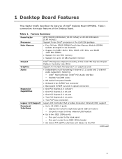
... This chapter briefly describes the features of the Desktop Board. Table 1. Table 1 summarizes the major features of Intel® Desktop Board DP55WG. Feature Summary Form Factor Processor Main Memory ATX (304.80 millimeters [12.00 inches] x 243.84 millimeters [9.60 inches]) Support for an Intel® processor in the LGA1156 package • Four 240-pin DDR3 SDRAM...
... This chapter briefly describes the features of the Desktop Board. Table 1. Table 1 summarizes the major features of Intel® Desktop Board DP55WG. Feature Summary Form Factor Processor Main Memory ATX (304.80 millimeters [12.00 inches] x 243.84 millimeters [9.60 inches]) Support for an Intel® processor in the LGA1156 package • Four 240-pin DDR3 SDRAM...
Product Guide
Page 13
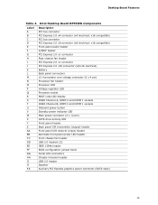
... pin) SATA drive activity LED Front panel header Back panel CIR transmitter (output) header Front panel CIR receiver (input) header Alternate front panel power LED header Front chassis fan header USB 2.0 headers (2) IEEE 1394a header BIOS configuration jumper block Serial ATA connectors Chassis intrusion header USB 2.0 header Speaker Auxiliary PCI Express graphics power connector (SATA-style) 13 Intel Desktop Board DP55WG Components Label A B C D E F G H I J K L M N O P Q R S T U V W X Y Z AA BB CC...
... pin) SATA drive activity LED Front panel header Back panel CIR transmitter (output) header Front panel CIR receiver (input) header Alternate front panel power LED header Front chassis fan header USB 2.0 headers (2) IEEE 1394a header BIOS configuration jumper block Serial ATA connectors Chassis intrusion header USB 2.0 header Speaker Auxiliary PCI Express graphics power connector (SATA-style) 13 Intel Desktop Board DP55WG Components Label A B C D E F G H I J K L M N O P Q R S T U V W X Y Z AA BB CC...

Product Guide
Page 16
Intel Desktop Board DP55WG Product Guide Intel® P55 Express Chipset The Intel P55 Express Chipset consists of the following components: • Intel® P55 PCH • Realtek ALC889 codec The subsystem has the following headers and connectors: • Back panel audio connectors, including S/PDIF in and out optical ports • High Definition Audio front panel header that provides mic in Table 3. 16 These...
Intel Desktop Board DP55WG Product Guide Intel® P55 Express Chipset The Intel P55 Express Chipset consists of the following components: • Intel® P55 PCH • Realtek ALC889 codec The subsystem has the following headers and connectors: • Back panel audio connectors, including S/PDIF in and out optical ports • High Definition Audio front panel header that provides mic in Table 3. 16 These...

Product Guide
Page 17
... includes a SATA drive activity indicator (a blue LED) shown in the BIOS reverts all USB 2.0 ports to three onboard headers). Desktop Board Features Figure 2. Disabling Hi-Speed USB in Figure 3. 17 USB 1.1 devices will function normally at USB 1.1 speeds. USB 2.0 support ...data rate 100 Mb/s data rate 1000 Mb/s data rate USB 2.0 Support The Desktop Board provides 14 USB 2.0 ports (eight ports routed to back panel connectors and six ports routed to USB 1.1 operation. Serial ATA Support Intel Desktop Board DP55WG supports six onboard 3.0 Gb/s Serial ATA (SATA) channels via the PCH.
... includes a SATA drive activity indicator (a blue LED) shown in the BIOS reverts all USB 2.0 ports to three onboard headers). Desktop Board Features Figure 2. Disabling Hi-Speed USB in Figure 3. 17 USB 1.1 devices will function normally at USB 1.1 speeds. USB 2.0 support ...data rate 100 Mb/s data rate 1000 Mb/s data rate USB 2.0 Support The Desktop Board provides 14 USB 2.0 ports (eight ports routed to back panel connectors and six ports routed to USB 1.1 operation. Serial ATA Support Intel Desktop Board DP55WG supports six onboard 3.0 Gb/s Serial ATA (SATA) channels via the PCH.

Product Guide
Page 22
... current when using this feature can adjust the fan speed or switch the fan on or off . Intel Desktop Board DP55WG Product Guide Fan Headers The function/operation of the fans is as needed. • All fan headers have a +12 V DC connection. Failure to support the standard Instantly Available (ACPI S3 sleep state) configuration. LAN...If the computer has a dual-colored power LED on when the computer is in the ACPI S0 state. • The fans are on the front panel, the sleep state is indicated by a wake-up of the computer through a network. Power supplies used with this...
... current when using this feature can adjust the fan speed or switch the fan on or off . Intel Desktop Board DP55WG Product Guide Fan Headers The function/operation of the fans is as needed. • All fan headers have a +12 V DC connection. Failure to support the standard Instantly Available (ACPI S3 sleep state) configuration. LAN...If the computer has a dual-colored power LED on when the computer is in the ACPI S0 state. • The fans are on the front panel, the sleep state is indicated by a wake-up of the computer through a network. Power supplies used with this...
Product Guide
Page 29
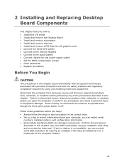
...workstation using and modifying electronic equipment. If such a station is not available, you can continue to operate even though the front panel power button is off. Failure to disconnect power, telecommunications links, networks, or modems before you begin: • Always follow the...I/O shield • Install and remove the Desktop Board • Install and remove a processor • Install and remove memory • Install and remove a PCI Express x16 graphics card • Connect the Serial ATA cables • Connect to the internal headers • Connect to the audio system &#...
...workstation using and modifying electronic equipment. If such a station is not available, you can continue to operate even though the front panel power button is off. Failure to disconnect power, telecommunications links, networks, or modems before you begin: • Always follow the...I/O shield • Install and remove the Desktop Board • Install and remove a processor • Install and remove memory • Install and remove a PCI Express x16 graphics card • Connect the Serial ATA cables • Connect to the internal headers • Connect to the audio system &#...

Product Guide
Page 49
The receiver header consists of the front panel Intel HD Audio header. NOTE The Consumer IR option must be enabled in order to control external electronic hardware. S/PDIF Header Signal Names Pin Description 1 Ground 2 S/PDIF Out 3 Key (no pin) 10 SENSE2_RETURN Consumer IR (CIR) Headers The Desktop Board has two CIR headers: the input or receiver header (Figure 27, C) and...
The receiver header consists of the front panel Intel HD Audio header. NOTE The Consumer IR option must be enabled in order to control external electronic hardware. S/PDIF Header Signal Names Pin Description 1 Ground 2 S/PDIF Out 3 Key (no pin) 10 SENSE2_RETURN Consumer IR (CIR) Headers The Desktop Board has two CIR headers: the input or receiver header (Figure 27, C) and...

Product Guide
Page 50
... individual wires from your chassis front panel to the front panel header, be sure to observe the connection polarity. Front Panel CIR Receiver (Input) Header Signal Names Pin Signal Name 1 Ground 3 No Connection 5 +5 V Standby 7 Key (no pin) 6 Jack Detect 2 Front Panel Header Figure 27, E shows the location of the front panel header. Intel Desktop Board DP55WG Product Guide Table 6 shows the pin...
... individual wires from your chassis front panel to the front panel header, be sure to observe the connection polarity. Front Panel CIR Receiver (Input) Header Signal Names Pin Signal Name 1 Ground 3 No Connection 5 +5 V Standby 7 Key (no pin) 6 Jack Detect 2 Front Panel Header Figure 27, E shows the location of the front panel header. Intel Desktop Board DP55WG Product Guide Table 6 shows the pin...

Product Guide
Page 51
... LED 2 No pin 3 Front panel yellow LED In/Out Out Out USB 2.0 Headers Figure 27, G shows the location of the alternate front panel power LED header. Installing and Replacing Desktop Board Components Alternate Front Panel Power LED Header Figure 27, F shows the location of the USB 2.0 headers. Pins 1 and 3 of the front panel header. Each USB header can be assigned as...
... LED 2 No pin 3 Front panel yellow LED In/Out Out Out USB 2.0 Headers Figure 27, G shows the location of the alternate front panel power LED header. Installing and Replacing Desktop Board Components Alternate Front Panel Power LED Header Figure 27, F shows the location of the USB 2.0 headers. Pins 1 and 3 of the front panel header. Each USB header can be assigned as...


