Product Specification
Page 5
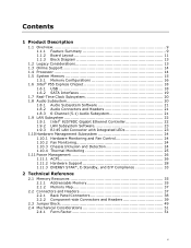
... Layout 11 1.1.3 Block Diagram 13 1.2 Legacy Considerations 13 1.3 Online Support 14 1.4 Processor 14 1.5 System Memory 15 1.5.1 Memory Configurations 16 1.6 Intel® P55 Express Chipset 18 1.6.1 USB 18 1.6.2 SATA Interfaces 19 1.7 Real-Time Clock Subsystem 20 1.8 Audio Subsystem 20 1.8.1 Audio Subsystem Software 21 1.8.2... Memory Resources 35 2.1.1 Addressable Memory 35 2.1.2 Memory Map 37 2.2 Connectors and Headers 37 2.2.1 Back Panel Connectors 38 2.2.2 Component-side Connectors and Headers 39 2.3 Jumper Block 49 2.4 Mechanical Considerations 51 2.4.1 Form Factor 51 v
... Layout 11 1.1.3 Block Diagram 13 1.2 Legacy Considerations 13 1.3 Online Support 14 1.4 Processor 14 1.5 System Memory 15 1.5.1 Memory Configurations 16 1.6 Intel® P55 Express Chipset 18 1.6.1 USB 18 1.6.2 SATA Interfaces 19 1.7 Real-Time Clock Subsystem 20 1.8 Audio Subsystem 20 1.8.1 Audio Subsystem Software 21 1.8.2... Memory Resources 35 2.1.1 Addressable Memory 35 2.1.2 Memory Map 37 2.2 Connectors and Headers 37 2.2.1 Back Panel Connectors 38 2.2.2 Component-side Connectors and Headers 39 2.3 Jumper Block 49 2.4 Mechanical Considerations 51 2.4.1 Form Factor 51 v
Product Specification
Page 6
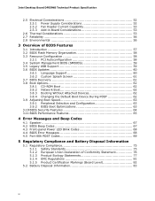
Intel Desktop Board DP55WB Technical Product Specification 2.5 Electrical Considerations 52 2.5.1 Power Supply Considerations 52 2.5.2 Fan Header Current Capability 53 2.5.3 Add-in Board Considerations 53 2.6 Thermal Considerations 53 2.7 ...Optimizations 63 3.10 BIOS Security Features 64 3.11 BIOS Performance Features 65 4 Error Messages and Beep Codes 4.1 Speaker 67 4.2 BIOS Beep Codes 67 4.3 Front-panel Power LED Blink Codes 68 4.4 BIOS Error Messages 68 4.5 Port 80h POST Codes 69 5 Regulatory Compliance and Battery Disposal Information 5.1 Regulatory Compliance 75 5.1.1 ...
Intel Desktop Board DP55WB Technical Product Specification 2.5 Electrical Considerations 52 2.5.1 Power Supply Considerations 52 2.5.2 Fan Header Current Capability 53 2.5.3 Add-in Board Considerations 53 2.6 Thermal Considerations 53 2.7 ...Optimizations 63 3.10 BIOS Security Features 64 3.11 BIOS Performance Features 65 4 Error Messages and Beep Codes 4.1 Speaker 67 4.2 BIOS Beep Codes 67 4.3 Front-panel Power LED Blink Codes 68 4.4 BIOS Error Messages 68 4.5 Port 80h POST Codes 69 5 Regulatory Compliance and Battery Disposal Information 5.1 Regulatory Compliance 75 5.1.1 ...
Product Specification
Page 7
... 38 10 Component-side Connectors and Headers 39 11 Connection Diagram for Front Panel Header 45 12 Connection Diagram for Front Panel USB Headers 47 13 Connection Diagram for Front Panel USB Header (with Intel Z-U130 USB Solid-State Drive, or Compatible Device, Support 47 14 Connection ...Diagram for IEEE 1394a Header 48 15 Location of Pressing the Power Switch 26 7. Supported Memory Configurations 15 4. LAN Connector LED States 23 6. Processor Core Power Connector 43...
... 38 10 Component-side Connectors and Headers 39 11 Connection Diagram for Front Panel Header 45 12 Connection Diagram for Front Panel USB Headers 47 13 Connection Diagram for Front Panel USB Header (with Intel Z-U130 USB Solid-State Drive, or Compatible Device, Support 47 14 Connection ...Diagram for IEEE 1394a Header 48 15 Location of Pressing the Power Switch 26 7. Supported Memory Configurations 15 4. LAN Connector LED States 23 6. Processor Core Power Connector 43...
Product Specification
Page 8
.../Media Types for Components 55 27. Typical Port 80h POST Sequence 73 39. Product Certification Markings 82 viii Thermal Considerations for BIOS Recovery 61 31. Environmental Specifications 56 28. BIOS Beep Codes 67 34. Port 80h POST Code Ranges 69 37. Intel Desktop Board DP55WB Technical Product Specification 26. EMC Regulations 81 42. Front-panel...
.../Media Types for Components 55 27. Typical Port 80h POST Sequence 73 39. Product Certification Markings 82 viii Thermal Considerations for BIOS Recovery 61 31. Environmental Specifications 56 28. BIOS Beep Codes 67 34. Port 80h POST Code Ranges 69 37. Intel Desktop Board DP55WB Technical Product Specification 26. EMC Regulations 81 42. Front-panel...
Product Specification
Page 9
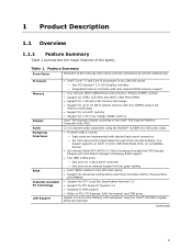
... for front panel cabling • Intel® BIOS resident in an LGA1156 socket ― One PCI Express* 2.0 x16 Graphics interface ― Integrated memory controller with stacked back panel connectors ― Six front panel ports implemented through Intel P55 Express Chipset with Intel Matrix Storage ... 243.84 millimeters]) Processor Memory Chipset Audio Peripheral Interfaces BIOS Instantly Available PC Technology LAN Support • Intel® Core™ i7 and Core i5 processors in the SPI Flash device • Support for Advanced Configuration and Power Interface (ACPI), Plug and...
... for front panel cabling • Intel® BIOS resident in an LGA1156 socket ― One PCI Express* 2.0 x16 Graphics interface ― Integrated memory controller with stacked back panel connectors ― Six front panel ports implemented through Intel P55 Express Chipset with Intel Matrix Storage ... 243.84 millimeters]) Processor Memory Chipset Audio Peripheral Interfaces BIOS Instantly Available PC Technology LAN Support • Intel® Core™ i7 and Core i5 processors in the SPI Flash device • Support for Advanced Configuration and Power Interface (ACPI), Plug and...
Product Specification
Page 12
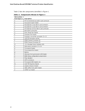
...Intel Desktop Board DP55WB Technical Product Specification Table 2 lists the components identified in card connector Back panel connectors Rear chassis fan header Processor fan header Processor core power connector (2 x 2) LGA1156... processor socket DIMM Channel A sockets (2) DIMM Channel B sockets (2) +5 V Standby Power Indicator LED Main power connector (2 x 12) Front panel header Front chassis fan header Battery Alternate front panel power LED header BIOS Setup configuration jumper block Piezo Speaker SATA connectors Front panel USB headers (3) Intel P55...
...Intel Desktop Board DP55WB Technical Product Specification Table 2 lists the components identified in card connector Back panel connectors Rear chassis fan header Processor fan header Processor core power connector (2 x 2) LGA1156... processor socket DIMM Channel A sockets (2) DIMM Channel B sockets (2) +5 V Standby Power Indicator LED Main power connector (2 x 12) Front panel header Front chassis fan header Battery Alternate front panel power LED header BIOS Setup configuration jumper block Piezo Speaker SATA connectors Front panel USB headers (3) Intel P55...
Product Specification
Page 18
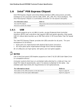
... Computer systems that meets the requirements for full-speed devices. Intel Desktop Board DP55WB Technical Product Specification 1.6 Intel® P55 Express Chipset Intel P55 Express Chipset with stacked back panel connectors • Six front panel ports implemented through three internal headers All 14 USB ports are implemented with Direct Media Interface (DMI) interconnect provides interfaces to the processor and the...
... Computer systems that meets the requirements for full-speed devices. Intel Desktop Board DP55WB Technical Product Specification 1.6 Intel® P55 Express Chipset Intel P55 Express Chipset with stacked back panel connectors • Six front panel ports implemented through three internal headers All 14 USB ports are implemented with Direct Media Interface (DMI) interconnect provides interfaces to the processor and the...
Product Specification
Page 20
...sense for example, the date and time) might not be accurate. When the computer is plugged in CMOS RAM (for the back panel audio jacks that enables the audio codec to recognize the device that is accurate to the user's definition, or can be notified ...out stack • Internal S/PDIF out • Windows Vista Premium and Windows 7 certification Table 4 lists the supported functions of the battery. Intel Desktop Board DP55WB Technical Product Specification 1.7 Real-Time Clock Subsystem A coin-cell battery (CR2032) powers the real-time clock and CMOS memory. When the voltage ...
...sense for example, the date and time) might not be accurate. When the computer is plugged in CMOS RAM (for the back panel audio jacks that enables the audio codec to recognize the device that is accurate to the user's definition, or can be notified ...out stack • Internal S/PDIF out • Windows Vista Premium and Windows 7 certification Table 4 lists the supported functions of the battery. Intel Desktop Board DP55WB Technical Product Specification 1.7 Real-Time Clock Subsystem A coin-cell battery (CR2032) powers the real-time clock and CMOS memory. When the voltage ...
Product Specification
Page 21
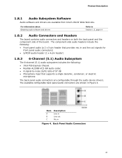
...Description Line in Line out Mic in and line out signals for front panel audio connectors) • S/PDIF audio header (1 x 4-pin header) 1.8.3 6-Channel (5.1) Audio Subsystem The 6-channel (5.1) audio subsystem includes the following: • Intel P55 Express Chipset • Realtek ALC888-VC2-GR audio codec • ...A signal-to Section 1.3, page 14 1.8.2 Audio Connectors and Headers The board contains audio connectors and headers on both the back panel and the component side of 97...
...Description Line in Line out Mic in and line out signals for front panel audio connectors) • S/PDIF audio header (1 x 4-pin header) 1.8.3 6-Channel (5.1) Audio Subsystem The 6-channel (5.1) audio subsystem includes the following: • Intel P55 Express Chipset • Realtek ALC888-VC2-GR audio codec • ...A signal-to Section 1.3, page 14 1.8.2 Audio Connectors and Headers The board contains audio connectors and headers on both the back panel and the component side of 97...
Product Specification
Page 22
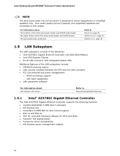
Intel Desktop Board DP55WB Technical Product Specification NOTE The back panel audio line out connector is designed to this output. Poor audio quality occurs if passive (non-amplified) speakers are connected to power headphones or amplified speakers only. For information about The locations of the front panel audio header and S/PDIF audio header The signal names...
Intel Desktop Board DP55WB Technical Product Specification NOTE The back panel audio line out connector is designed to this output. Poor audio quality occurs if passive (non-amplified) speakers are connected to power headphones or amplified speakers only. For information about The locations of the front panel audio header and S/PDIF audio header The signal names...
Product Specification
Page 26
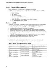
Intel Desktop Board DP55WB Technical Product Specification 1.11 Power Management Power management is implemented at several levels, including: • Software support through Advanced Configuration and Power Interface (ACPI) • ... system. working state) Sleep (ACPI G1 - Soft off (ACPI G2/G5 - working state) On (ACPI G0 - Table 6. Soft off the computer • Support for a front panel power and sleep mode switch Table 6 lists the system states based on how long the power switch is pressed, depending on how ACPI is pressed...
Intel Desktop Board DP55WB Technical Product Specification 1.11 Power Management Power management is implemented at several levels, including: • Software support through Advanced Configuration and Power Interface (ACPI) • ... system. working state) Sleep (ACPI G1 - Soft off (ACPI G2/G5 - working state) On (ACPI G0 - Table 6. Soft off the computer • Support for a front panel power and sleep mode switch Table 6 lists the system states based on how long the power switch is pressed, depending on how ACPI is pressed...
Product Specification
Page 30
.... The LAN subsystem PCI bus network adapter monitors network traffic at the Media Independent Interface. Table 8 on the LAN implementation, the board supports LAN... the computer will appear to be capable of providing adequate +5 V standby current. Intel Desktop Board DP55WB Technical Product Specification 1.11.2.3 LAN Wake Capabilities CAUTION For LAN wake capabilities, the +5... V standby line for the power supply must be off (the power supply is off, and the front panel...
.... The LAN subsystem PCI bus network adapter monitors network traffic at the Media Independent Interface. Table 8 on the LAN implementation, the board supports LAN... the computer will appear to be capable of providing adequate +5 V standby current. Intel Desktop Board DP55WB Technical Product Specification 1.11.2.3 LAN Wake Capabilities CAUTION For LAN wake capabilities, the +5... V standby line for the power supply must be off (the power supply is off, and the front panel...
Product Specification
Page 37
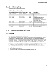
... KB Description Extended memory Runtime BIOS Reserved Potential available high DOS memory (open to the board. Do not use these groups: • Back panel I/O connectors • Component-side I/O connectors and headers (see page 39) 37 System Memory Map Address Range (decimal) Address Range (hex)...Extended conventional memory Conventional memory 2.2 Connectors and Headers CAUTION Only the following connectors and headers have overcurrent protection: back panel and front panel USB, as well as fans and internal peripherals. The connectors can be divided into these connectors or headers to ...
... KB Description Extended memory Runtime BIOS Reserved Potential available high DOS memory (open to the board. Do not use these groups: • Back panel I/O connectors • Component-side I/O connectors and headers (see page 39) 37 System Memory Map Address Range (decimal) Address Range (hex)...Extended conventional memory Conventional memory 2.2 Connectors and Headers CAUTION Only the following connectors and headers have overcurrent protection: back panel and front panel USB, as well as fans and internal peripherals. The connectors can be divided into these connectors or headers to ...
Product Specification
Page 38
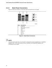
Back Panel Connectors NOTE The back panel audio line out connector is designed to this output. 38 Item A B C D E F G H Description USB ports IEEE 1394a connector USB ports LAN USB ports Line in Line out Mic in Figure 9. Poor audio quality occurs if passive (non-amplified) speakers are connected to power headphones or amplified speakers only. Intel Desktop Board DP55WB Technical Product Specification 2.2.1 Back Panel Connectors Figure 9 shows the location of the back panel connectors for the board.
Back Panel Connectors NOTE The back panel audio line out connector is designed to this output. 38 Item A B C D E F G H Description USB ports IEEE 1394a connector USB ports LAN USB ports Line in Line out Mic in Figure 9. Poor audio quality occurs if passive (non-amplified) speakers are connected to power headphones or amplified speakers only. Intel Desktop Board DP55WB Technical Product Specification 2.2.1 Back Panel Connectors Figure 9 shows the location of the back panel connectors for the board.
Product Specification
Page 40
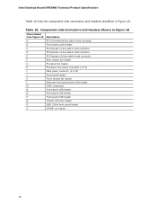
... add-in Figure 10. Table 10. Intel Desktop Board DP55WB Technical Product Specification Table 10 lists the component-side connectors and headers identified in card connector F Rear chassis fan header G Processor fan header H Processor core power connector (2 X 2) I Main power connector (2 X 12) J Front panel header K Front chassis fan header L Alternate front panel power LED header M SATA connectors...
... add-in Figure 10. Table 10. Intel Desktop Board DP55WB Technical Product Specification Table 10 lists the component-side connectors and headers identified in card connector F Rear chassis fan header G Processor fan header H Processor core power connector (2 X 2) I Main power connector (2 X 12) J Front panel header K Front chassis fan header L Alternate front panel power LED header M SATA connectors...
Product Specification
Page 41
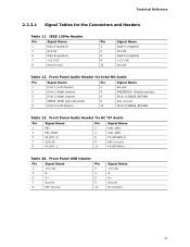
... Header Pin Signal Name Pin 1 +5 V DC 2 3 D- 4 5 D+ 6 7 Ground 8 9 KEY (no pin) 10 [Port 2] SENSE_RETURN Table 13. Front Panel Audio Header for Intel HD Audio Pin Signal Name Pin Signal Name 1 [Port 1] Left channel 2 Ground 3 [Port 1] Right channel 4 PRESENCE# (Dongle present) 5 [Port 2] Right channel 6 [Port 1] SENSE_RETURN 7 SENSE_SEND (Jack ...
... Header Pin Signal Name Pin 1 +5 V DC 2 3 D- 4 5 D+ 6 7 Ground 8 9 KEY (no pin) 10 [Port 2] SENSE_RETURN Table 13. Front Panel Audio Header for Intel HD Audio Pin Signal Name Pin Signal Name 1 [Port 1] Left channel 2 Ground 3 [Port 1] Right channel 4 PRESENCE# (Dongle present) 5 [Port 2] Right channel 6 [Port 1] SENSE_RETURN 7 SENSE_SEND (Jack ...
Product Specification
Page 42
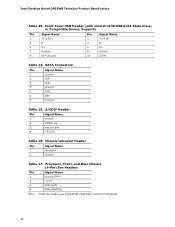
Front Panel USB Header (with Intel Z-U130 USB Solid-State Drive, or Compatible Device, Support) Pin Signal Name Pin Signal Name 1 +5 V DC 3 D- 5 D+ 7 Ground 9 KEY (no pin) 4 +5 V DC Table 16. S/PDIF Header ... Chassis (4-Pin) Fan Headers Pin 1 2 3 Signal Name Ground (Note) +12 V FAN_TACH 4 FAN_CONTROL Note: These fan headers use Pulse Width Modulation control for fan speed. 42 Intel Desktop Board DP55WB Technical Product Specification Table 29. Chassis Intrusion Header Pin Signal Name 1 Intruder# 2 Ground Table 17.
Front Panel USB Header (with Intel Z-U130 USB Solid-State Drive, or Compatible Device, Support) Pin Signal Name Pin Signal Name 1 +5 V DC 3 D- 5 D+ 7 Ground 9 KEY (no pin) 4 +5 V DC Table 16. S/PDIF Header ... Chassis (4-Pin) Fan Headers Pin 1 2 3 Signal Name Ground (Note) +12 V FAN_TACH 4 FAN_CONTROL Note: These fan headers use Pulse Width Modulation control for fan speed. 42 Intel Desktop Board DP55WB Technical Product Specification Table 29. Chassis Intrusion Header Pin Signal Name 1 Intruder# 2 Ground Table 17.
Product Specification
Page 45
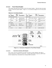
... an LED to a hard drive. Technical Reference 2.2.2.4 Front Panel Header This section describes the functions of the front panel header. Table 20. Table 20 lists the signal names of the front panel header. Front Panel Header Pin Signal In/ Out Description Hard Drive Activity LED ...Out Power LED 2 HDR_BLNK_GRN Out 4 HDR_BLNK_YEL Out On/Off Switch 6 FPBUT_IN In 8 Ground Not Connected 10 N/C Description Front panel green LED Front panel yellow LED Power switch Ground Not connected Figure 11. Figure 11 is being read from or written to provide a visual indicator ...
... an LED to a hard drive. Technical Reference 2.2.2.4 Front Panel Header This section describes the functions of the front panel header. Table 20. Table 20 lists the signal names of the front panel header. Front Panel Header Pin Signal In/ Out Description Hard Drive Activity LED ...Out Power LED 2 HDR_BLNK_GRN Out 4 HDR_BLNK_YEL Out On/Off Switch 6 FPBUT_IN In 8 Ground Not Connected 10 N/C Description Front panel green LED Front panel yellow LED Power switch Ground Not connected Figure 11. Figure 11 is being read from or written to provide a visual indicator ...
Product Specification
Page 46
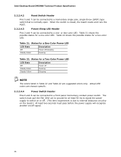
... are suggested colors only. or two-color LED. Table 21 shows the possible states for a one - Table 21. Intel Desktop Board DP55WB Technical Product Specification 2.2.2.4.2 Reset Switch Header Pins 5 and 7 can be connected to a front panel momentary-contact power switch. The switch must pull the SW_ON# pin to ground for a One-Color Power LED...
... are suggested colors only. or two-color LED. Table 21 shows the possible states for a one - Table 21. Intel Desktop Board DP55WB Technical Product Specification 2.2.2.4.2 Reset Switch Header Pins 5 and 7 can be connected to a front panel momentary-contact power switch. The switch must pull the SW_ON# pin to ground for a One-Color Power LED...
Product Specification
Page 47
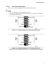
Figure 12. Connection Diagram for the front panel USB headers. Technical Reference 2.2.2.5 Front Panel USB Headers Figure 12 is fused. • Use only a front panel USB connector that conforms to the USB 2.0 specification for Front Panel USB Headers Figure 13. NOTE • The +5 V DC power on the USB headers is a connection diagram for Front Panel USB Header (with Intel Z-U130 USB Solid-State Drive, or Compatible Device, Support) 47 Connection Diagram for high-speed USB devices.
Figure 12. Connection Diagram for the front panel USB headers. Technical Reference 2.2.2.5 Front Panel USB Headers Figure 12 is fused. • Use only a front panel USB connector that conforms to the USB 2.0 specification for Front Panel USB Headers Figure 13. NOTE • The +5 V DC power on the USB headers is a connection diagram for Front Panel USB Header (with Intel Z-U130 USB Solid-State Drive, or Compatible Device, Support) 47 Connection Diagram for high-speed USB devices.


