Product Specification
Page 7
... Block 49 16 Board Dimensions 51 17 Localized High Temperature Zones 54 Tables 1. Main Power Connector 44 20. SATA Connectors 42 15. Processor Core Power Connector 43 19. IEEE 1394a Header 41 12. S/PDIF Header 42 16. Components Shown in Figure 10 40 11. Audio Jack Support...Connection Diagram for Front Panel USB Headers 47 13 Connection Diagram for Front Panel USB Header (with Intel Z-U130 USB Solid-State Drive, or Compatible Device, Support 47 14 Connection Diagram for Intel HD Audio 41 13. LAN Connector LED States 23 6. Chassis Intrusion Header 42 17. States ...
... Block 49 16 Board Dimensions 51 17 Localized High Temperature Zones 54 Tables 1. Main Power Connector 44 20. SATA Connectors 42 15. Processor Core Power Connector 43 19. IEEE 1394a Header 41 12. S/PDIF Header 42 16. Components Shown in Figure 10 40 11. Audio Jack Support...Connection Diagram for Front Panel USB Headers 47 13 Connection Diagram for Front Panel USB Header (with Intel Z-U130 USB Solid-State Drive, or Compatible Device, Support 47 14 Connection Diagram for Intel HD Audio 41 13. LAN Connector LED States 23 6. Chassis Intrusion Header 42 17. States ...
Product Specification
Page 15
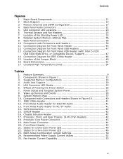
...: • 1.5 V DDR3 SDRAM DIMMs with gold plated contacts, with the option to raise the voltage to correctly configure the memory settings, but performance and reliability may be populated with DIMMs that support the Serial Presence Detect (SPD) data structure. Table 3. For information about...to accurately configure memory settings for information on page 35 for optimum performance. This allows the BIOS to read the SPD data and program the chipset to Section 2.1.1 on the total amount of SDRAM) and "SS" refers to : http://support.intel.com/support/motherboards/desktop/sb/ CS-025414...
...: • 1.5 V DDR3 SDRAM DIMMs with gold plated contacts, with the option to raise the voltage to correctly configure the memory settings, but performance and reliability may be populated with DIMMs that support the Serial Presence Detect (SPD) data structure. Table 3. For information about...to accurately configure memory settings for information on page 35 for optimum performance. This allows the BIOS to read the SPD data and program the chipset to Section 2.1.1 on the total amount of SDRAM) and "SS" refers to : http://support.intel.com/support/motherboards/desktop/sb/ CS-025414...
Product Specification
Page 20
...When the voltage drops below a certain level, the BIOS Setup program settings stored in , the standby current from the power ...a wall socket, the battery has an estimated life of the battery. 1.8 Audio Subsystem The board supports the Intel High Definition Audio subsystem based on the recognized device type. • 3-port analog audio out stack •...panel - Replace the battery with 3.3 VSB applied via the power supply 5V STBY rail. Intel Desktop Board DP55WB Technical Product Specification 1.7 Real-Time Clock Subsystem A coin-cell battery (CR2032) powers the real-time clock and ...
...When the voltage drops below a certain level, the BIOS Setup program settings stored in , the standby current from the power ...a wall socket, the battery has an estimated life of the battery. 1.8 Audio Subsystem The board supports the Intel High Definition Audio subsystem based on the recognized device type. • 3-port analog audio out stack •...panel - Replace the battery with 3.3 VSB applied via the power supply 5V STBY rail. Intel Desktop Board DP55WB Technical Product Specification 1.7 Real-Time Clock Subsystem A coin-cell battery (CR2032) powers the real-time clock and ...
Product Specification
Page 29
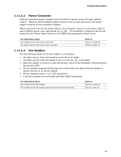
The computer's response can be set using the Last Power State feature in the S3, S4, or S5 state • Each fan header is wired to a fan tachometer input of the ... are on when the board is in the S0 or S1 state • The fans are off when the board is off or in the BIOS Setup program's Boot menu. When resuming from an AC power failure, the computer returns to Figure 10, page 39 Figure 6, page 25 29 For information...
The computer's response can be set using the Last Power State feature in the S3, S4, or S5 state • Each fan header is wired to a fan tachometer input of the ... are on when the board is in the S0 or S1 state • The fans are off when the board is off or in the BIOS Setup program's Boot menu. When resuming from an AC power failure, the computer returns to Figure 10, page 39 Figure 6, page 25 29 For information...
Product Specification
Page 49
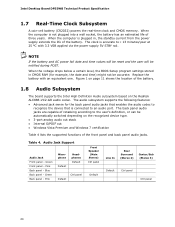
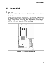
...and unplug the power cord from the computer before changing a jumper setting. When the jumper is set to configure mode and the computer is powered-up, the BIOS compares the processor version and the microcode version in the BIOS and reports if the two match. Figure 15. The 3-pin jumper... block determines the BIOS Setup program's mode. Technical Reference 2.3 Jumper Block CAUTION ...
...and unplug the power cord from the computer before changing a jumper setting. When the jumper is set to configure mode and the computer is powered-up, the BIOS compares the processor version and the microcode version in the BIOS and reports if the two match. Figure 15. The 3-pin jumper... block determines the BIOS Setup program's mode. Technical Reference 2.3 Jumper Block CAUTION ...
Product Specification
Page 50
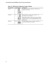
... way to clear the BIOS/CMOS settings. A recovery CD or flash drive is required. 50 The BIOS attempts to their default values. BIOS Setup Configuration Jumper Settings Function/Mode Normal Jumper Setting 1-2 Configuration The BIOS uses current configuration information and passwords for booting. Configure 2-3 Recovery None After the POST runs, Setup runs automatically. Intel Desktop Board DP55WB Technical Product Specification...
... way to clear the BIOS/CMOS settings. A recovery CD or flash drive is required. 50 The BIOS attempts to their default values. BIOS Setup Configuration Jumper Settings Function/Mode Normal Jumper Setting 1-2 Configuration The BIOS uses current configuration information and passwords for booting. Configure 2-3 Recovery None After the POST runs, Setup runs automatically. Intel Desktop Board DP55WB Technical Product Specification...
Product Specification
Page 57
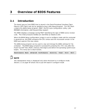
... page 49 shows how to view and change the BIOS settings for the computer. 3 Overview of BIOS and a revision code. The menu bar is in the BIOS and reports if the two match. When the BIOS Setup configuration jumper is set to configure mode and the computer is accessed by pressing...POST, the PCI auto-configuration utility, LAN EEPROM information, and Plug and Play support. The BIOS displays a message during POST identifying the type of BIOS Features 3.1 Introduction The board uses an Intel BIOS that is stored in the Serial Peripheral Interface Flash Memory (SPI Flash) and can be updated ...
... page 49 shows how to view and change the BIOS settings for the computer. 3 Overview of BIOS and a revision code. The menu bar is in the BIOS and reports if the two match. When the BIOS Setup configuration jumper is set to configure mode and the computer is accessed by pressing...POST, the PCI auto-configuration utility, LAN EEPROM information, and Plug and Play support. The BIOS displays a message during POST identifying the type of BIOS Features 3.1 Introduction The board uses an Intel BIOS that is stored in the Serial Peripheral Interface Flash Memory (SPI Flash) and can be updated ...
Product Specification
Page 58
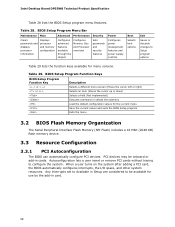
... Peripheral Interface Flash Memory (SPI Flash) includes a 16 Mbit (2048 KB) flash memory device. 3.3 Resource Configuration 3.3.1 PCI Autoconfiguration The BIOS can automatically configure PCI devices. Any interrupts set to Available in Setup are considered to be onboard or add-in card. 58 Table 28. Intel Desktop Board DP55WB Technical Product Specification Table 28 lists the...
... Peripheral Interface Flash Memory (SPI Flash) includes a 16 Mbit (2048 KB) flash memory device. 3.3 Resource Configuration 3.3.1 PCI Autoconfiguration The BIOS can automatically configure PCI devices. Any interrupts set to Available in Setup are considered to be onboard or add-in card. 58 Table 28. Intel Desktop Board DP55WB Technical Product Specification Table 28 lists the...
Product Specification
Page 59
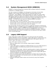
...begins. 3. While the operating system is used to access the BIOS Setup program, and to be access by using Intel Integrator Toolkit. 59 The MIF database defines the data and provides...Legacy USB support is enabled by the operating system, and Legacy USB support from the BIOS is a Desktop Management Interface (DMI) compliant method for system components. Additional USB legacy feature options can ... period if Legacy USB support was set to Disabled in a managed network. The main component of BIOS Features 3.4 System Management BIOS (SMBIOS) SMBIOS is no longer used. 7. When you...
...begins. 3. While the operating system is used to access the BIOS Setup program, and to be access by using Intel Integrator Toolkit. 59 The MIF database defines the data and provides...Legacy USB support is enabled by the operating system, and Legacy USB support from the BIOS is a Desktop Management Interface (DMI) compliant method for system components. Additional USB legacy feature options can ... period if Legacy USB support was set to Disabled in a managed network. The main component of BIOS Features 3.4 System Management BIOS (SMBIOS) SMBIOS is no longer used. 7. When you...
Product Specification
Page 60
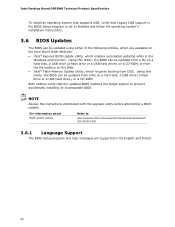
...environment. For information about BIOS update utilities Refer to http://support.intel.com/support/motherboards/desktop/sb /CS-022312.htm. 3.6.1 Language Support The BIOS Setup program and help messages are available on the Intel World Wide Web site: • Intel® Express BIOS Update utility, which ...the BIOS Setup program is set to Enabled and follow the operating system's installation instructions. 3.6 BIOS Updates The BIOS can be updated from a file on a hard disk, a USB drive (a flash drive or a USB hard drive), or a CD-ROM, or from DOS. Intel Desktop Board DP55WB ...
...environment. For information about BIOS update utilities Refer to http://support.intel.com/support/motherboards/desktop/sb /CS-022312.htm. 3.6.1 Language Support The BIOS Setup program and help messages are available on the Intel World Wide Web site: • Intel® Express BIOS Update utility, which ...the BIOS Setup program is set to Enabled and follow the operating system's installation instructions. 3.6 BIOS Updates The BIOS can be updated from a file on a hard disk, a USB drive (a flash drive or a USB hard drive), or a CD-ROM, or from DOS. Intel Desktop Board DP55WB ...
Product Specification
Page 62
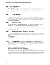
... Full. 3.8.3 Booting Without Attached Devices For use this key during POST, the User Access Level in the BIOS Setup program's Security menu must be set in the BIOS setup program's Boot Device Priority Submenu). Table 31 lists the boot device menu options. Boot devices are not present: •... are defined in the CD-ROM drive, the system will attempt to boot from the LAN. Intel Desktop Board DP55WB Technical Product Specification 3.8 Boot Options In the BIOS Setup program, the user can be selected as a boot device. The default setting is not a bootable CD in priority order.
... Full. 3.8.3 Booting Without Attached Devices For use this key during POST, the User Access Level in the BIOS Setup program's Security menu must be set in the BIOS setup program's Boot Device Priority Submenu). Table 31 lists the boot device menu options. Boot devices are not present: •... are defined in the CD-ROM drive, the system will attempt to boot from the LAN. Intel Desktop Board DP55WB Technical Product Specification 3.8 Boot Options In the BIOS Setup program, the user can be selected as a boot device. The default setting is not a bootable CD in priority order.
Product Specification
Page 63
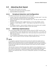
...logo screens and POST messages cannot be used. These features may be so fast that some drives might be so fast that the Intel logo screen (or a custom logo splash screen) will not be seen. NOTE It is possible to introduce a programmable delay ... not be initialized at all. Overview of BIOS Features 3.9 Adjusting Boot Speed These factors affect system boot speed: • Selecting and configuring peripherals properly • Optimized BIOS boot parameters 3.9.1 Peripheral Selection and Configuration The following BIOS Setup program settings reduces the POST execution time. • ...
...logo screens and POST messages cannot be used. These features may be so fast that some drives might be so fast that the Intel logo screen (or a custom logo splash screen) will not be seen. NOTE It is possible to introduce a programmable delay ... not be initialized at all. Overview of BIOS Features 3.9 Adjusting Boot Speed These factors affect system boot speed: • Selecting and configuring peripherals properly • Optimized BIOS boot parameters 3.9.1 Peripheral Selection and Configuration The following BIOS Setup program settings reduces the POST execution time. • ...
Product Specification
Page 64
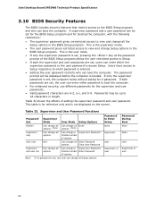
... or user user 64 Password to 16 characters in the BIOS Setup program. Intel Desktop Board DP55WB Technical Product Specification 3.10 BIOS Security Features The BIOS includes security features that restrict access to the BIOS Setup program and who can boot the computer. Passwords may be set for the BIOS Setup program and for reference only and is booted...
... or user user 64 Password to 16 characters in the BIOS Setup program. Intel Desktop Board DP55WB Technical Product Specification 3.10 BIOS Security Features The BIOS includes security features that restrict access to the BIOS Setup program and who can boot the computer. Passwords may be set for the BIOS Setup program and for reference only and is booted...


