Product Specification
Page 5
Contents 1 Product Description 1.1 Overview 9 1.1.1 Feature Summary 9 1.1.2 Board Layout 11 1.1.3 Block Diagram 13 1.2 Legacy Considerations 13 1.3 Online Support 14 1.4 Processor 14 1.5 System Memory 15 1.5.1 Memory Configurations 16 1.6 Intel® P55 Express Chipset 18 1.6.1 USB 18 1.6.2 SATA Interfaces 19 1.7 Real-Time Clock Subsystem 20 1.8 Audio Subsystem 20 1.8.1 Audio Subsystem Software 21 1.8.2 Audio Connectors and Headers 21 1.8.3 6-...
Contents 1 Product Description 1.1 Overview 9 1.1.1 Feature Summary 9 1.1.2 Board Layout 11 1.1.3 Block Diagram 13 1.2 Legacy Considerations 13 1.3 Online Support 14 1.4 Processor 14 1.5 System Memory 15 1.5.1 Memory Configurations 16 1.6 Intel® P55 Express Chipset 18 1.6.1 USB 18 1.6.2 SATA Interfaces 19 1.7 Real-Time Clock Subsystem 20 1.8 Audio Subsystem 20 1.8.1 Audio Subsystem Software 21 1.8.2 Audio Connectors and Headers 21 1.8.3 6-...
Product Specification
Page 6
Intel Desktop Board DP55WB Technical Product Specification 2.5 Electrical Considerations 52 2.5.1 Power Supply Considerations 52 2.5.2 Fan Header Current Capability 53 2.5.3 Add-in Board Considerations 53 2.6 Thermal Considerations 53 2.7 Reliability 56 2.8 Environmental 56 3 Overview of BIOS Features 3.1 Introduction 57 3.2 BIOS Flash Memory Organization 58 3.3 Resource Configuration... Default Boot Device During POST 62 3.9 Adjusting Boot Speed 63 3.9.1 Peripheral Selection and Configuration 63 3.9.2 BIOS Boot Optimizations 63 3.10 BIOS Security Features 64 3.11 BIOS Performance ...
Intel Desktop Board DP55WB Technical Product Specification 2.5 Electrical Considerations 52 2.5.1 Power Supply Considerations 52 2.5.2 Fan Header Current Capability 53 2.5.3 Add-in Board Considerations 53 2.6 Thermal Considerations 53 2.7 Reliability 56 2.8 Environmental 56 3 Overview of BIOS Features 3.1 Introduction 57 3.2 BIOS Flash Memory Organization 58 3.3 Resource Configuration... Default Boot Device During POST 62 3.9 Adjusting Boot Speed 63 3.9.1 Peripheral Selection and Configuration 63 3.9.2 BIOS Boot Optimizations 63 3.10 BIOS Security Features 64 3.11 BIOS Performance ...
Product Specification
Page 7
...Front Panel Audio Header for AC '97 Audio 41 14. Front Panel Audio Header for Intel HD Audio 41 13. Chassis Intrusion Header 42 17. Main Power Connector 44 20. Recommended...Figure 1 12 3. S/PDIF Header 42 16. Processor Core Power Connector 43 19. States for a Two-Color Power LED 46 23. BIOS Setup Configuration Jumper Settings 50 24. Processor, Front, and Rear ...in Figure 10 40 11. IEEE 1394a Header 41 12. Fan Header Current Capability 53 vii Supported Memory Configurations 15 4. Power States and Targeted System Power 27 8. SATA Connectors 42 15. States for a One...
...Front Panel Audio Header for AC '97 Audio 41 14. Front Panel Audio Header for Intel HD Audio 41 13. Chassis Intrusion Header 42 17. Main Power Connector 44 20. Recommended...Figure 1 12 3. S/PDIF Header 42 16. Processor Core Power Connector 43 19. States for a Two-Color Power LED 46 23. BIOS Setup Configuration Jumper Settings 50 24. Processor, Front, and Rear ...in Figure 10 40 11. IEEE 1394a Header 41 12. Fan Header Current Capability 53 vii Supported Memory Configurations 15 4. Power States and Targeted System Power 27 8. SATA Connectors 42 15. States for a One...
Product Specification
Page 9
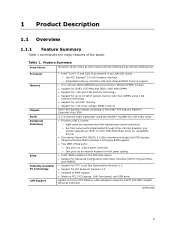
...Memory Chipset Audio Peripheral Interfaces BIOS Instantly Available PC Technology LAN Support • Intel® Core™ i7 and Core i5 processors in the SPI Flash device • Support for Advanced Configuration... connectors ― Six front panel ports implemented through Intel P55 Express Chipset with Intel Matrix Storage Technology RAID support • Two IEEE...Intel® BIOS resident in an LGA1156 socket ― One PCI Express* 2.0 x16 Graphics interface ― Integrated memory controller with dual channel DDR3 memory support • Four 240-pin DDR3 SDRAM Dual Inline Memory...
...Memory Chipset Audio Peripheral Interfaces BIOS Instantly Available PC Technology LAN Support • Intel® Core™ i7 and Core i5 processors in the SPI Flash device • Support for Advanced Configuration... connectors ― Six front panel ports implemented through Intel P55 Express Chipset with Intel Matrix Storage Technology RAID support • Two IEEE...Intel® BIOS resident in an LGA1156 socket ― One PCI Express* 2.0 x16 Graphics interface ― Integrated memory controller with dual channel DDR3 memory support • Four 240-pin DDR3 SDRAM Dual Inline Memory...
Product Specification
Page 14
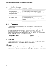
... support the Intel Core i7 and Core i5 processors in an LGA1156 socket Other processors may be supported in the future. Intel Desktop Board DP55WB Technical Product Specification 1.3 Online Support To find information about ... Intel Desktop Board DP55WB Desktop Board Support Available configurations for this World Wide Web site: http://www.intel.com/products/motherboard/DP55WB/index.htm http://support.intel.com/support/motherboards/desktop http://www.intel.com/products/motherboard/DP55WB/index...
... support the Intel Core i7 and Core i5 processors in an LGA1156 socket Other processors may be supported in the future. Intel Desktop Board DP55WB Technical Product Specification 1.3 Online Support To find information about ... Intel Desktop Board DP55WB Desktop Board Support Available configurations for this World Wide Web site: http://www.intel.com/products/motherboard/DP55WB/index.htm http://support.intel.com/support/motherboards/desktop http://www.intel.com/products/motherboard/DP55WB/index...
Product Specification
Page 15
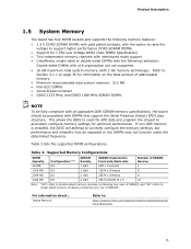
... chipset to : http://support.intel.com/support/motherboards/desktop/sb/ CS-025414.htm 15 Table 3. Refer to correctly configure the memory settings, but performance and reliability may not function under the determined frequency. If non-SPD memory is installed, the BIOS will attempt to Section 2.1.1 on the total amount of SDRAM). Supported Memory Configurations DIMM Capacity 512MB 1024...
... chipset to : http://support.intel.com/support/motherboards/desktop/sb/ CS-025414.htm 15 Table 3. Refer to correctly configure the memory settings, but performance and reliability may not function under the determined frequency. If non-SPD memory is installed, the BIOS will attempt to Section 2.1.1 on the total amount of SDRAM). Supported Memory Configurations DIMM Capacity 512MB 1024...
Product Specification
Page 16
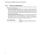
... when the installed memory capacities of memory organization: • Dual channel (Interleaved) mode. Intel Desktop Board DP55WB Technical Product Specification 1.5.1 Memory Configurations The Intel Core i7 and Core i5 processors in the LGA1156 socket support the following types of both DIMM channels are used between channels, the slowest memory timing will be ... information about... Technology and device width can vary from one channel to : http://www.intel.com/support/motherboards/desktop/sb/cs011965.htm 16 This mode offers the highest throughput for real world applications.
... when the installed memory capacities of memory organization: • Dual channel (Interleaved) mode. Intel Desktop Board DP55WB Technical Product Specification 1.5.1 Memory Configurations The Intel Core i7 and Core i5 processors in the LGA1156 socket support the following types of both DIMM channels are used between channels, the slowest memory timing will be ... information about... Technology and device width can vary from one channel to : http://www.intel.com/support/motherboards/desktop/sb/cs011965.htm 16 This mode offers the highest throughput for real world applications.
Product Specification
Page 17
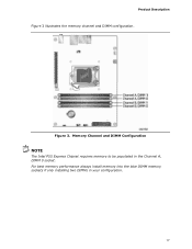
Figure 3. Product Description Figure 3 illustrates the memory channel and DIMM configuration. Memory Channel and DIMM Configuration NOTE The Intel P55 Express Chipset requires memory to be populated in your configuration. 17 For best memory performance always install memory into the blue DIMM memory sockets if only installing two DIMMs in the Channel A, DIMM 0 socket.
Figure 3. Product Description Figure 3 illustrates the memory channel and DIMM configuration. Memory Channel and DIMM Configuration NOTE The Intel P55 Express Chipset requires memory to be populated in your configuration. 17 For best memory performance always install memory into the blue DIMM memory sockets if only installing two DIMMs in the Channel A, DIMM 0 socket.
Product Specification
Page 35
...) • Local APIC (19 MB) • Direct Media Interface (40 MB) • Front side bus interrupts (17 MB) • PCI Express configuration space (256 MB) • PCH base address registers PCI Express ports (up to 256 MB) • Memory-mapped I/O that has 16 GB of system memory installed, it is allocated for other system...
...) • Local APIC (19 MB) • Direct Media Interface (40 MB) • Front side bus interrupts (17 MB) • PCI Express configuration space (256 MB) • PCH base address registers PCI Express ports (up to 256 MB) • Memory-mapped I/O that has 16 GB of system memory installed, it is allocated for other system...
Product Specification
Page 57
...Intel BIOS that is stored in the BIOS and reports if the two match. The menu bar is accessed by pressing the key after the Power-On Self-Test (POST) memory test begins and before the operating system boot begins. Section 2.3 on page 49 shows how to put the board in configure... compares the CPU version and the microcode version in the Serial Peripheral Interface Flash Memory (SPI Flash) and can be updated using a disk-based program. 3 Overview of BIOS and a revision code. When the BIOS Setup configuration jumper is set to view and change the BIOS settings for the computer. The...
...Intel BIOS that is stored in the BIOS and reports if the two match. The menu bar is accessed by pressing the key after the Power-On Self-Test (POST) memory test begins and before the operating system boot begins. Section 2.3 on page 49 shows how to put the board in configure... compares the CPU version and the microcode version in the Serial Peripheral Interface Flash Memory (SPI Flash) and can be updated using a disk-based program. 3 Overview of BIOS and a revision code. When the BIOS Setup configuration jumper is set to view and change the BIOS settings for the computer. The...
Product Specification
Page 58
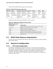
Intel Desktop Board DP55WB Technical Product Specification Table 28 lists the BIOS Setup program menu features. BIOS Setup Program Function Keys BIOS Setup Program Function Key ... Bar Maintenance Main Advanced Performance Security Clears passwords and displays processor information Displays processor and memory configuration Configures advanced features available through the chipset Configures Memory, Bus and Processor overrides Sets passwords and security features Power Configures power management features and power supply controls Boot Selects boot options Exit Saves or discards ...
Intel Desktop Board DP55WB Technical Product Specification Table 28 lists the BIOS Setup program menu features. BIOS Setup Program Function Keys BIOS Setup Program Function Key ... Bar Maintenance Main Advanced Performance Security Clears passwords and displays processor information Displays processor and memory configuration Configures advanced features available through the chipset Configures Memory, Bus and Processor overrides Sets passwords and security features Power Configures power management features and power supply controls Boot Selects boot options Exit Saves or discards ...
Product Specification
Page 59
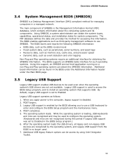
...operating system can be used even when the operating system's USB drivers are recognized by using Intel Integrator Toolkit. 59 Legacy USB support is used . 7. POST begins. 3. While the...-system data, such as peripherals, serial numbers, and asset tags • Resource data, such as memory size, cache size, and processor speed • Dynamic data, such as follows: 1. POST completes.... keyboard to enter and configure the BIOS Setup program and the maintenance menu. 4. Legacy USB support is a Desktop Management Interface (DMI) compliant method for system components.
...operating system can be used even when the operating system's USB drivers are recognized by using Intel Integrator Toolkit. 59 Legacy USB support is used . 7. POST begins. 3. While the...-system data, such as peripherals, serial numbers, and asset tags • Resource data, such as memory size, cache size, and processor speed • Dynamic data, such as follows: 1. POST completes.... keyboard to enter and configure the BIOS Setup program and the maintenance menu. 4. Legacy USB support is a Desktop Management Interface (DMI) compliant method for system components.
Product Specification
Page 70
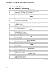
Intel Desktop Board DP55WB Technical Product Specification Table 37. Port 80h POST Codes POST Code Description of POST Operation Host Processor 10 Power-on initialization of the host processor (Boot Strap Processor) 11 Host processor cache initialization (including APs) 12 Starting Application processor initialization 13 SMM initialization Chipset 21 Initializing a chipset component Memory 22 Reading...
Intel Desktop Board DP55WB Technical Product Specification Table 37. Port 80h POST Codes POST Code Description of POST Operation Host Processor 10 Power-on initialization of the host processor (Boot Strap Processor) 11 Host processor cache initialization (including APs) 12 Starting Application processor initialization 13 SMM initialization Chipset 21 Initializing a chipset component Memory 22 Reading...

Product Specification
Page 71
... etc.) B3 Enabling/configuring a fixed media Removable Media B8 Resetting removable media B9 Disabling removable media BA Detecting presence of a removable media (CD-ROM detection, etc.) BC Enabling/configuring a removable media BDS Dy Trying boot selection y (y=0 to 15) PEI Core E0 Started dispatching PEIMs (emitted on first report of EFI_SW_PC_INIT_BEGIN EFI_SW_PEI_PC_HANDOFF_TO_NEXT) E2 E1, E3 Permanent memory found Reserved for PEI...
... etc.) B3 Enabling/configuring a fixed media Removable Media B8 Resetting removable media B9 Disabling removable media BA Detecting presence of a removable media (CD-ROM detection, etc.) BC Enabling/configuring a removable media BDS Dy Trying boot selection y (y=0 to 15) PEI Core E0 Started dispatching PEIMs (emitted on first report of EFI_SW_PC_INIT_BEGIN EFI_SW_PEI_PC_HANDOFF_TO_NEXT) E2 E1, E3 Permanent memory found Reserved for PEI...
Product Specification
Page 73
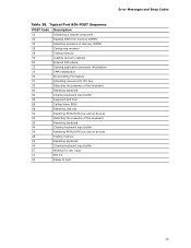
Typical Port 80h POST Sequence POST Code Description 21 Initializing a chipset component 22 Reading SPD from memory DIMMs 23 Detecting presence of memory DIMMs 25 Configuring memory 28 Testing memory 34 Loading recovery capsule E4 Entered DXE phase 12 Starting application processor initialization 13 SMM initialization ... the keyboard 90 Resetting keyboard 94 Clearing keyboard input buffer 5A Resetting PATA/SATA bus and all devices 28 Testing memory 90 Resetting keyboard 94 Clearing keyboard input buffer E7 Waiting for user input 01 INT 19 00 Ready to boot ...
Typical Port 80h POST Sequence POST Code Description 21 Initializing a chipset component 22 Reading SPD from memory DIMMs 23 Detecting presence of memory DIMMs 25 Configuring memory 28 Testing memory 34 Loading recovery capsule E4 Entered DXE phase 12 Starting application processor initialization 13 SMM initialization ... the keyboard 90 Resetting keyboard 94 Clearing keyboard input buffer 5A Resetting PATA/SATA bus and all devices 28 Testing memory 90 Resetting keyboard 94 Clearing keyboard input buffer E7 Waiting for user input 01 INT 19 00 Ready to boot ...


