
Technical Product Specification
Page 7
... Summary 11 1.1.2 Board Layout 13 1.1.3 Block Diagram 15 1.2 Online Support 16 1.3 Processor 16 1.3.1 Graphics Subsystem 17 1.4 System Memory 19 1.4.1 Memory Configurations 20 1.5 Intel® H77 Express Chipset 22 1.5.1 Direct Media Interface (DMI 22 1.5.2 Display Interfaces 22 1.5.3 USB 25 1.5.4 SATA Interfaces 25 1.6 Real-Time Clock Subsystem 27 1.7...Hardware Support 36 2 Technical Reference 2.1 Memory Resources 41 2.1.1 Addressable Memory 41 2.1.2 Memory Map 43 2.2 Connectors and Headers 43 2.2.1 Back Panel Connectors 44 2.2.2 Component-side Connectors and Headers 45 vii
... Summary 11 1.1.2 Board Layout 13 1.1.3 Block Diagram 15 1.2 Online Support 16 1.3 Processor 16 1.3.1 Graphics Subsystem 17 1.4 System Memory 19 1.4.1 Memory Configurations 20 1.5 Intel® H77 Express Chipset 22 1.5.1 Direct Media Interface (DMI 22 1.5.2 Display Interfaces 22 1.5.3 USB 25 1.5.4 SATA Interfaces 25 1.6 Real-Time Clock Subsystem 27 1.7...Hardware Support 36 2 Technical Reference 2.1 Memory Resources 41 2.1.1 Addressable Memory 41 2.1.2 Memory Map 43 2.2 Connectors and Headers 43 2.2.1 Back Panel Connectors 44 2.2.2 Component-side Connectors and Headers 45 vii
Technical Product Specification
Page 8
Intel Desktop Board DH77EB Technical Product Specification 2.3 Jumper Block 57 2.4 Mechanical Considerations 59 2.4.1 Form Factor 59 2.5 Electrical Considerations 60 2.5.1 Power Supply Considerations 60 2.5.2 Power Supervisor 60 2.5.3 Fan Header ...Boot Optimizations 71 3.10 BIOS Security Features 72 3.11 BIOS Performance Features 73 4 Error Messages and Beep Codes 4.1 Speaker 75 4.2 BIOS Beep Codes 75 4.3 Front-panel Power LED Blink Codes 76 4.4 BIOS Error Messages 76 4.5 Port 80h Power On Self Test (POST) Codes 77 5 Regulatory Compliance and Battery Disposal Information 5.1 ...
Intel Desktop Board DH77EB Technical Product Specification 2.3 Jumper Block 57 2.4 Mechanical Considerations 59 2.4.1 Form Factor 59 2.5 Electrical Considerations 60 2.5.1 Power Supply Considerations 60 2.5.2 Power Supervisor 60 2.5.3 Fan Header ...Boot Optimizations 71 3.10 BIOS Security Features 72 3.11 BIOS Performance Features 73 4 Error Messages and Beep Codes 4.1 Speaker 75 4.2 BIOS Beep Codes 75 4.3 Front-panel Power LED Blink Codes 76 4.4 BIOS Error Messages 76 4.5 Port 80h Power On Self Test (POST) Codes 77 5 Regulatory Compliance and Battery Disposal Information 5.1 ...
Technical Product Specification
Page 9
Memory Channel and DIMM Configuration 21 4. Thermal Sensors and Fan Headers 33 7. Back Panel Connectors 44 10. Connection Diagram for Intel HD Audio 47 16. Board Dimensions 59 15. Localized High Temperature Zones 62 16. DVI Port Status Conditions 23 5. HDMI Port Status ...45 11. Location of Pressing the Power Switch 34 11. Intel Desktop Board DH77EB China RoHS Material Self Declaration Table 88 Tables 1. Audio Jack Support 28 9. Effects of the Jumper Block 57 14. Front Panel USB 3.0 Connector 48 19. Back Panel Audio Connectors 29 5. Detailed System Memory Address Map 42 9....
Memory Channel and DIMM Configuration 21 4. Thermal Sensors and Fan Headers 33 7. Back Panel Connectors 44 10. Connection Diagram for Intel HD Audio 47 16. Board Dimensions 59 15. Localized High Temperature Zones 62 16. DVI Port Status Conditions 23 5. HDMI Port Status ...45 11. Location of Pressing the Power Switch 34 11. Intel Desktop Board DH77EB China RoHS Material Self Declaration Table 88 Tables 1. Audio Jack Support 28 9. Effects of the Jumper Block 57 14. Front Panel USB 3.0 Connector 48 19. Back Panel Audio Connectors 29 5. Detailed System Memory Address Map 42 9....
Technical Product Specification
Page 10
... Setup Configuration Jumper Settings 58 36. Fan Header Current Capability 61 37. BIOS Beep Codes 75 46. EMC Regulations 89 53. Front Panel CIR Receiver (Input) Header 49 25. PCI Express Full-/Half-Mini Card Connector 51 27. Tcontrol Values for BIOS Recovery 69 43....a One-Color Power LED 55 33. Boot Device Menu Options 70 44. Safety Standards 83 52. Intel Desktop Board DH77EB Technical Product Specification 21. Chassis Intrusion Header 49 22. Back Panel CIR Emitter (Output) Header 49 24. Environmental Specifications 64 40. BIOS Error Messages 76 48. LPC ...
... Setup Configuration Jumper Settings 58 36. Fan Header Current Capability 61 37. BIOS Beep Codes 75 46. EMC Regulations 89 53. Front Panel CIR Receiver (Input) Header 49 25. PCI Express Full-/Half-Mini Card Connector 51 27. Tcontrol Values for BIOS Recovery 69 43....a One-Color Power LED 55 33. Boot Device Menu Options 70 44. Safety Standards 83 52. Intel Desktop Board DH77EB Technical Product Specification 21. Chassis Intrusion Header 49 22. Back Panel CIR Emitter (Output) Header 49 24. Environmental Specifications 64 40. BIOS Error Messages 76 48. LPC ...
Technical Product Specification
Page 12
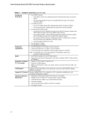
Intel Desktop Board DH77EB Technical Product Specification Table 1. Feature Summary (continued) Peripheral Interfaces Expansion Capabilities BIOS • Four USB 3.0 ports: ― Two USB 3.0 ports are implemented with stacked back panel connectors (blue) ― Two front panel USB 3.0 ports are implemented through one internal ...to RAM support • Wake on PCI Express, LAN, front panel, serial, Consumer Infrared (CIR), and USB ports LAN Support Gigabit (10/100/1000 Mb/s) LAN subsystem using the Intel® 82579V Gigabit Ethernet Controller Legacy I/O Control Nuvoton W83677HG-i I/O ...
Intel Desktop Board DH77EB Technical Product Specification Table 1. Feature Summary (continued) Peripheral Interfaces Expansion Capabilities BIOS • Four USB 3.0 ports: ― Two USB 3.0 ports are implemented with stacked back panel connectors (blue) ― Two front panel USB 3.0 ports are implemented through one internal ...to RAM support • Wake on PCI Express, LAN, front panel, serial, Consumer Infrared (CIR), and USB ports LAN Support Gigabit (10/100/1000 Mb/s) LAN subsystem using the Intel® 82579V Gigabit Ethernet Controller Legacy I/O Control Nuvoton W83677HG-i I/O ...
Technical Product Specification
Page 14
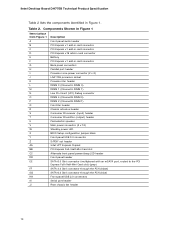
... add-in card connector D PCI Express x16 add-in card connector E Battery F PCI Express x1 add-in Figure 1. Intel Desktop Board DH77EB Technical Product Specification Table 2 lists the components identified in card connector G Back panel connectors H Parallel port header I Processor core power connector (2 x 2) J LGA1155 processor socket K Processor fan header L DIMM 3 (Channel A DIMM 0) M DIMM...
... add-in card connector D PCI Express x16 add-in card connector E Battery F PCI Express x1 add-in Figure 1. Intel Desktop Board DH77EB Technical Product Specification Table 2 lists the components identified in card connector G Back panel connectors H Parallel port header I Processor core power connector (2 x 2) J LGA1155 processor socket K Processor fan header L DIMM 3 (Channel A DIMM 0) M DIMM...
Technical Product Specification
Page 22
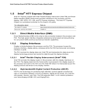
... high definition content against unauthorized copy or unreceptive between a source (computer, digital set top boxes, etc.) and the sink (panels, monitor, and TVs). The processor houses the memory interface, display planes, and pipes while the PCH has transcoder and display interface...Intel® FDI) Intel FDI connects the display engine in the display engine of the processor and sent to -chip connection between the processor and the PCH. The PCH supports HDCP 1.4 for the board's I/O paths. Intel Desktop Board DH77EB Technical Product Specification 1.5 Intel® H77 Express Chipset Intel...
... high definition content against unauthorized copy or unreceptive between a source (computer, digital set top boxes, etc.) and the sink (panels, monitor, and TVs). The processor houses the memory interface, display planes, and pipes while the PCH has transcoder and display interface...Intel® FDI) Intel FDI connects the display engine in the display engine of the processor and sent to -chip connection between the processor and the PCH. The PCH supports HDCP 1.4 for the board's I/O paths. Intel Desktop Board DH77EB Technical Product Specification 1.5 Intel® H77 Express Chipset Intel...
Technical Product Specification
Page 25
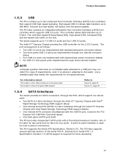
...high-speed, full-speed, and low-speed capable. All ports are implemented with stacked back panel connectors (black) • Six USB 2.0 front panel ports implemented through the Intel H77 Express Chipset with Intel Rapid Storage Technology RAID support (black) • One internal SATA connector (multiplexed with the ...mSATA port, routed to the PCI Express Full-/Half-Mini Card slot) (gray) • One back panel eSATA port (red) The PCH provides independent SATA ports with Intel® Rapid Storage Technology RAID support (blue) • Two internal Serial ATA (SATA) 3.0 Gb/s interfaces...
...high-speed, full-speed, and low-speed capable. All ports are implemented with stacked back panel connectors (black) • Six USB 2.0 front panel ports implemented through the Intel H77 Express Chipset with Intel Rapid Storage Technology RAID support (black) • One internal SATA connector (multiplexed with the ...mSATA port, routed to the PCI Express Full-/Half-Mini Card slot) (gray) • One back panel eSATA port (red) The PCH provides independent SATA ports with Intel® Rapid Storage Technology RAID support (blue) • Two internal Serial ATA (SATA) 3.0 Gb/s interfaces...
Technical Product Specification
Page 28
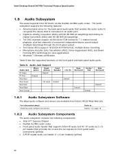
... Default Rear Blue Rear Green Ctrl panel Rear Pink Rear Black Rear Orange Front Speaker Default Line In Default Rear Center/ Surround Sub Default Default Side Surround Default 1.8.1 Audio Subsystem Software The latest audio software and drivers are available from Intel's World Wide Web site. Intel Desktop Board DH77EB Technical Product Specification 1.8 Audio Subsystem...
... Default Rear Blue Rear Green Ctrl panel Rear Pink Rear Black Rear Orange Front Speaker Default Line In Default Rear Center/ Surround Sub Default Default Side Surround Default 1.8.1 Audio Subsystem Software The latest audio software and drivers are available from Intel's World Wide Web site. Intel Desktop Board DH77EB Technical Product Specification 1.8 Audio Subsystem...
Technical Product Specification
Page 29
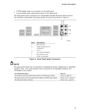
...• S/PDIF digital audio out connector on the back panel • 5-port analog audio input/output stack on the back panel The back panel audio connectors are connected to this output. Back Panel Audio Connectors NOTE The back panel audio line out connector is designed to Figure 10, page ... page 47 Section 2.2.1, page 44 29 For information about The locations of the front panel audio header and S/PDIF audio header The signal names of the front panel audio header and S/PDIF audio header The back panel audio connectors Refer to power headphones or amplified speakers only. Item A B C D ...
...• S/PDIF digital audio out connector on the back panel • 5-port analog audio input/output stack on the back panel The back panel audio connectors are connected to this output. Back Panel Audio Connectors NOTE The back panel audio line out connector is designed to Figure 10, page ... page 47 Section 2.2.1, page 44 29 For information about The locations of the front panel audio header and S/PDIF audio header The signal names of the front panel audio header and S/PDIF audio header The back panel audio connectors Refer to power headphones or amplified speakers only. Item A B C D ...
Technical Product Specification
Page 34
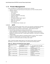
Soft off (ACPI G2/G5 - working state) Soft-off (ACPI G2/G5 - working state) On (ACPI G0 - Intel Desktop Board DH77EB Technical Product Specification 1.11 Power Management Power management is pressed for Less than four seconds Less than four seconds More than six seconds Less than ...individual devices, add-in boards (some add-in boards may require an ACPI-aware driver), video displays, and hard disk drives • Methods for a front panel power and sleep mode switch Table 10 lists the system states based on how long the power switch is pressed, depending on how ACPI is...
Soft off (ACPI G2/G5 - working state) Soft-off (ACPI G2/G5 - working state) On (ACPI G0 - Intel Desktop Board DH77EB Technical Product Specification 1.11 Power Management Power management is pressed for Less than four seconds Less than four seconds More than six seconds Less than ...individual devices, add-in boards (some add-in boards may require an ACPI-aware driver), video displays, and hard disk drives • Methods for a front panel power and sleep mode switch Table 10 lists the system states based on how long the power switch is pressed, depending on how ACPI is...
Technical Product Specification
Page 38
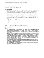
... standby current when implementing LAN wake capabilities can damage the power supply. Failure to be off (the power supply is off, and the front panel LED is amber if dual colored, or off if single colored.) When signaled by a wake-up the computer. Table 12 on the LAN ...implementation, the board supports LAN wake capabilities with ACPI in power management and can wake the computer from the S3 state. Intel Desktop Board DH77EB Technical Product Specification 1.11.2.3 LAN Wake Capabilities CAUTION For LAN wake capabilities, the +5 V standby line for the power supply must be ...
... standby current when implementing LAN wake capabilities can damage the power supply. Failure to be off (the power supply is off, and the front panel LED is amber if dual colored, or off if single colored.) When signaled by a wake-up the computer. Table 12 on the LAN ...implementation, the board supports LAN wake capabilities with ACPI in power management and can wake the computer from the S3 state. Intel Desktop Board DH77EB Technical Product Specification 1.11.2.3 LAN Wake Capabilities CAUTION For LAN wake capabilities, the +5 V standby line for the power supply must be ...
Technical Product Specification
Page 43
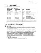
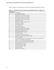
.... The other internal connectors and headers are not overcurrent protected and should connect only to the computer's chassis. Do not use these groups: • Back panel I/O connectors • Component-side connectors and headers (see page 45) 43 A fault in the load presented by memory manager software) Extended conventional memory Conventional memory...
.... The other internal connectors and headers are not overcurrent protected and should connect only to the computer's chassis. Do not use these groups: • Back panel I/O connectors • Component-side connectors and headers (see page 45) 43 A fault in the load presented by memory manager software) Extended conventional memory Conventional memory...
Technical Product Specification
Page 44
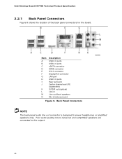
... and LFE (subwoofer) S/PDIF out (optical) Line in Line out/front speakers Mic-in/side surround Figure 9. Intel Desktop Board DH77EB Technical Product Specification 2.2.1 Back Panel Connectors Figure 9 shows the location of the back panel connectors for the board. Back Panel Connectors NOTE The back panel audio line out connector is designed to this output. 44
... and LFE (subwoofer) S/PDIF out (optical) Line in Line out/front speakers Mic-in/side surround Figure 9. Intel Desktop Board DH77EB Technical Product Specification 2.2.1 Back Panel Connectors Figure 9 shows the location of the back panel connectors for the board. Back Panel Connectors NOTE The back panel audio line out connector is designed to this output. 44
Technical Product Specification
Page 46
... 10 Item/callout f rom Figure 10 Description A Front panel audio header B PCI Express x1 add-in card connector C PCI Express x1 add-in card connector D PCI Express x16 add-in card connector E PCI Express x1 add-in Figure 10. Table 14. Intel Desktop Board DH77EB Technical Product Specification Table 14 lists the component...
... 10 Item/callout f rom Figure 10 Description A Front panel audio header B PCI Express x1 add-in card connector C PCI Express x1 add-in card connector D PCI Express x16 add-in card connector E PCI Express x1 add-in Figure 10. Table 14. Intel Desktop Board DH77EB Technical Product Specification Table 14 lists the component...
Technical Product Specification
Page 47
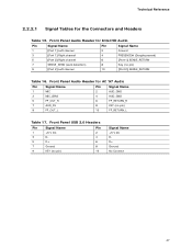
... Header for the Connectors and Headers Table 15. Front Panel USB 2.0 Headers Pin Signal Name Pin 1 +5 V DC 2 3 D- 4 5 D+ 6 7 Ground 8 9 KEY (no pin) 9 [Port 2] Left channel 10 [Port 2] SENSE_RETURN Table ...Signal Name Pin Signal Name 1 MIC 3 MIC_BIAS 5 FP_OUT_R 7 AUD_5V 2 AUD_GND 4 AUD_GND 6 FP_RETURN_R 8 KEY (no pin) 9 FP_OUT_L 10 FP_RETURN_L Table 17. Front Panel Audio Header for Intel HD Audio Pin Signal Name Pin Signal Name 1 [Port 1] Left channel 2 Ground 3 [Port 1] Right channel 4 PRESENCE# (Dongle present) 5 [Port 2] Right ...
... Header for the Connectors and Headers Table 15. Front Panel USB 2.0 Headers Pin Signal Name Pin 1 +5 V DC 2 3 D- 4 5 D+ 6 7 Ground 8 9 KEY (no pin) 9 [Port 2] Left channel 10 [Port 2] SENSE_RETURN Table ...Signal Name Pin Signal Name 1 MIC 3 MIC_BIAS 5 FP_OUT_R 7 AUD_5V 2 AUD_GND 4 AUD_GND 6 FP_RETURN_R 8 KEY (no pin) 9 FP_OUT_L 10 FP_RETURN_L Table 17. Front Panel Audio Header for Intel HD Audio Pin Signal Name Pin Signal Name 1 [Port 1] Left channel 2 Ground 3 [Port 1] Right channel 4 PRESENCE# (Dongle present) 5 [Port 2] Right ...
Technical Product Specification
Page 48
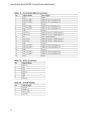
Front Panel USB 3.0 Connector Pin Signal Name 1 Vbus 2 IntA_P1_SSRX− Description Power USB3 ICC Port1 SuperSpeed Rx− 3 IntA_P1_SSRX+ USB3 ICC Port1 SuperSpeed Rx+ 4 GND 5 IntA_P1_SSTX− 6 ... Pin Signal Name 1 Ground 2 S/PDIF out 3 Key (no pin) 4 +5 V DC 48 SATA Connectors Pin Signal Name 1 Ground 2 TXP 3 TXN 4 Ground 5 RXN 6 RXP 7 Ground Table 20. Intel Desktop Board DH77EB Technical Product Specification Table 18.
Front Panel USB 3.0 Connector Pin Signal Name 1 Vbus 2 IntA_P1_SSRX− Description Power USB3 ICC Port1 SuperSpeed Rx− 3 IntA_P1_SSRX+ USB3 ICC Port1 SuperSpeed Rx+ 4 GND 5 IntA_P1_SSTX− 6 ... Pin Signal Name 1 Ground 2 S/PDIF out 3 Key (no pin) 4 +5 V DC 48 SATA Connectors Pin Signal Name 1 Ground 2 TXP 3 TXN 4 Ground 5 RXN 6 RXP 7 Ground Table 20. Intel Desktop Board DH77EB Technical Product Specification Table 18.
Technical Product Specification
Page 49
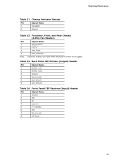
Technical Reference Table 21. Back Panel CIR Emitter (Output) Header Pin Signal Name 1 Emitter out 1 2 Emitter out 2 3 Ground 4 Key (no pin) 8 CIR Input 49 Chassis Intrusion Header Pin Signal Name 1 Intruder# 2 ... Chassis (4-Pin) Fan Headers Pin Signal Name 1 Ground (Note) 2 +12 V 3 FAN_TACH 4 FAN_CONTROL Note: These fan headers use Pulse Width Modulation control for fan speed. Front Panel CIR Receiver (Input) Header Pin Signal Name 1 Ground 2 LED 3 NC 4 Learn-in 5 5 V standby 6 VCC 7 Key (no pin) 5 Jack detect 1 6 Jack detect 2 Table 24...
Technical Reference Table 21. Back Panel CIR Emitter (Output) Header Pin Signal Name 1 Emitter out 1 2 Emitter out 2 3 Ground 4 Key (no pin) 8 CIR Input 49 Chassis Intrusion Header Pin Signal Name 1 Intruder# 2 ... Chassis (4-Pin) Fan Headers Pin Signal Name 1 Ground (Note) 2 +12 V 3 FAN_TACH 4 FAN_CONTROL Note: These fan headers use Pulse Width Modulation control for fan speed. Front Panel CIR Receiver (Input) Header Pin Signal Name 1 Ground 2 LED 3 NC 4 Learn-in 5 5 V standby 6 VCC 7 Key (no pin) 5 Jack detect 1 6 Jack detect 2 Table 24...
Technical Product Specification
Page 54
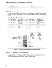
...# [In] Reset switch 8 GROUND 9 +5V_DC Power 10 Key Description [Out] Front panel LED (main color) [Out] Front panel LED (alt color) [In] Power switch Ground No pin Figure 11. Front Panel Header Pin Signal Name Description Pin Signal Name 1 HDD_POWER_LED Pull-up resistor (750 2 POWER_LED_MAIN... of the front panel header. Proper LED function requires a SATA hard drive or optical drive connected to Section 2.5.1 on page 60 2.2.2.4 Front Panel Header This section describes the functions of the front panel header. Intel Desktop Board DH77EB Technical Product Specification ...
...# [In] Reset switch 8 GROUND 9 +5V_DC Power 10 Key Description [Out] Front panel LED (main color) [Out] Front panel LED (alt color) [In] Power switch Ground No pin Figure 11. Front Panel Header Pin Signal Name Description Pin Signal Name 1 HDD_POWER_LED Pull-up resistor (750 2 POWER_LED_MAIN... of the front panel header. Proper LED function requires a SATA hard drive or optical drive connected to Section 2.5.1 on page 60 2.2.2.4 Front Panel Header This section describes the functions of the front panel header. Intel Desktop Board DH77EB Technical Product Specification ...
Technical Product Specification
Page 55
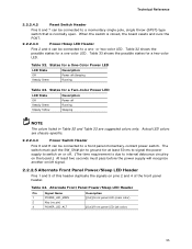
... in Table 32 and Table 33 are chassis-specific. 2.2.2.4.4 Power Switch Header Pins 6 and 8 can be connected to a front panel momentary-contact power switch. or two-color LED. Table 33 shows the possible states for a Two-Color Power LED LED State Description... Off Power off signal. 2.2.2.5 Alternate Front Panel Power/Sleep LED Header Pins 1 and 3 of the front panel header. Alternate Front Panel Power/Sleep LED Header Pin Signal Name 1 POWER_LED_MAIN 2 Key (no pin) 3 POWER_LED_ALT Description [Out...
... in Table 32 and Table 33 are chassis-specific. 2.2.2.4.4 Power Switch Header Pins 6 and 8 can be connected to a front panel momentary-contact power switch. or two-color LED. Table 33 shows the possible states for a Two-Color Power LED LED State Description... Off Power off signal. 2.2.2.5 Alternate Front Panel Power/Sleep LED Header Pins 1 and 3 of the front panel header. Alternate Front Panel Power/Sleep LED Header Pin Signal Name 1 POWER_LED_MAIN 2 Key (no pin) 3 POWER_LED_ALT Description [Out...


