
Technical Product Specification
Page 8
Intel Desktop Board DH77EB Technical Product Specification 2.3 Jumper Block 57 2.4 Mechanical Considerations 59 2.4.1 Form Factor 59 2.5 Electrical Considerations 60 2.5.1 Power Supply Considerations 60 2.5.2 Power Supervisor 60 2.5.3 Fan Header Current Capability 61 2.5.4 Add-in Board Considerations 61 2.6 Thermal Considerations 61 2.7 Reliability 64 2.8 Environmental 64 3 Overview of BIOS Features 3.1 Introduction 65 3.2 BIOS Flash Memory Organization 66 3.3 Resource Configuration...
Intel Desktop Board DH77EB Technical Product Specification 2.3 Jumper Block 57 2.4 Mechanical Considerations 59 2.4.1 Form Factor 59 2.5 Electrical Considerations 60 2.5.1 Power Supply Considerations 60 2.5.2 Power Supervisor 60 2.5.3 Fan Header Current Capability 61 2.5.4 Add-in Board Considerations 61 2.6 Thermal Considerations 61 2.7 Reliability 64 2.8 Environmental 64 3 Overview of BIOS Features 3.1 Introduction 65 3.2 BIOS Flash Memory Organization 66 3.3 Resource Configuration...
Technical Product Specification
Page 10
...Sequence 82 51. Regulatory Compliance Marks 92 x Parallel Port Header 50 26. Alternate Front Panel Power/Sleep LED Header 55 35. BIOS Setup Program Function Keys 66 42. Front-panel Power LED Blink Codes 76 47. Safety Standards 83 52. Back Panel CIR Emitter .... PCI Express Full-/Half-Mini Card Connector 51 27. Main Power Connector 53 31. BIOS Setup Configuration Jumper Settings 58 36. Thermal Considerations for a One-Color Power LED 55 33. Intel Desktop Board DH77EB Technical Product Specification 21. Processor, Front, and Rear Chassis (4-Pin) Fan Headers 49...
...Sequence 82 51. Regulatory Compliance Marks 92 x Parallel Port Header 50 26. Alternate Front Panel Power/Sleep LED Header 55 35. BIOS Setup Program Function Keys 66 42. Front-panel Power LED Blink Codes 76 47. Safety Standards 83 52. Back Panel CIR Emitter .... PCI Express Full-/Half-Mini Card Connector 51 27. Main Power Connector 53 31. BIOS Setup Configuration Jumper Settings 58 36. Thermal Considerations for a One-Color Power LED 55 33. Intel Desktop Board DH77EB Technical Product Specification 21. Processor, Front, and Rear Chassis (4-Pin) Fan Headers 49...
Technical Product Specification
Page 14
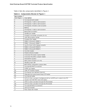
Intel Desktop Board DH77EB Technical Product Specification Table 2 lists the components identified in card connector G Back panel connectors H Parallel port header I Processor core power connector (2 x 2) J LGA1155 ...receiver (input) header T Consumer IR emitter (output) header U Piezoelectric speaker V Main power connector (2 x 12) W Standby power LED X BIOS Setup configuration jumper block Y Front panel USB 3.0 connector Z S/PDIF out header AA Intel H77 Express Chipset BB PCI Express Full-/Half-Mini Card slot CC Alternate front panel power/sleep LED header DD...
Intel Desktop Board DH77EB Technical Product Specification Table 2 lists the components identified in card connector G Back panel connectors H Parallel port header I Processor core power connector (2 x 2) J LGA1155 ...receiver (input) header T Consumer IR emitter (output) header U Piezoelectric speaker V Main power connector (2 x 12) W Standby power LED X BIOS Setup configuration jumper block Y Front panel USB 3.0 connector Z S/PDIF out header AA Intel H77 Express Chipset BB PCI Express Full-/Half-Mini Card slot CC Alternate front panel power/sleep LED header DD...
Technical Product Specification
Page 57
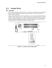
...13 shows the location of the Jumper Block 57 The 3-pin jumper block determines the BIOS Setup program's mode. When the jumper is set to configure mode and the computer is powered-up, the BIOS compares the processor version and the microcode version in the BIOS and reports if the two ...match. Table 35 describes the jumper settings for the three modes: normal, configure, and recovery. Location of the jumper block. Figure 13. Technical Reference 2.3 Jumper Block CAUTION Do not move the jumper with the power on. Always ...
...13 shows the location of the Jumper Block 57 The 3-pin jumper block determines the BIOS Setup program's mode. When the jumper is set to configure mode and the computer is powered-up, the BIOS compares the processor version and the microcode version in the BIOS and reports if the two ...match. Table 35 describes the jumper settings for the three modes: normal, configure, and recovery. Location of the jumper block. Figure 13. Technical Reference 2.3 Jumper Block CAUTION Do not move the jumper with the power on. Always ...
Technical Product Specification
Page 58
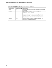
...) while in Configure mode to restore the BIOS/CMOS settings to their default values. The maintenance menu is required. 58 Intel Desktop Board DH77EB Technical Product Specification Table 35. A recovery CD or flash drive is displayed. BIOS Setup Configuration Jumper Settings Function/Mode Normal Configure Jumper Setting 1-2 2-3 Configuration The BIOS uses current configuration information and passwords for...
...) while in Configure mode to restore the BIOS/CMOS settings to their default values. The maintenance menu is required. 58 Intel Desktop Board DH77EB Technical Product Specification Table 35. A recovery CD or flash drive is displayed. BIOS Setup Configuration Jumper Settings Function/Mode Normal Configure Jumper Setting 1-2 2-3 Configuration The BIOS uses current configuration information and passwords for...
Technical Product Specification
Page 65
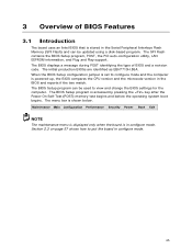
...Power Boot Exit NOTE The maintenance menu is displayed only when the board is shown below. The BIOS displays a message during POST identifying the type of BIOS Features 3.1 Introduction The board uses an Intel BIOS that is accessed by pressing the key after the Power-On Self-Test (POST) memory test ...begins and before the operating system boot begins. The BIOS Setup program can be used to view and change the BIOS settings for the computer. The menu bar is in configure mode. 65 When the BIOS Setup configuration jumper is set to put the board in configure mode.
...Power Boot Exit NOTE The maintenance menu is displayed only when the board is shown below. The BIOS displays a message during POST identifying the type of BIOS Features 3.1 Introduction The board uses an Intel BIOS that is accessed by pressing the key after the Power-On Self-Test (POST) memory test ...begins and before the operating system boot begins. The BIOS Setup program can be used to view and change the BIOS settings for the computer. The menu bar is in configure mode. 65 When the BIOS Setup configuration jumper is set to put the board in configure mode.

