

Technical Product Specification
Page 8
Intel Desktop Board DH77DF Technical Product Specification 2.3 Jumper Block 59 2.4 Mechanical Considerations 61 2.4.1 Form Factor 61 2.5 Electrical Considerations 62 2.5.1 Power Supply Considerations 62 2.5.2 Power Supervisor 63 2.5.3 Fan Header Current Capability 63 2.5.4 Add-in Board Considerations 63 2.6 Thermal Considerations 64 2.7 Reliability 67 2.8 Environmental 67 3 Overview of BIOS Features 3.1 Introduction 69 3.2 BIOS Flash Memory Organization 70 3.3 Resource...
Intel Desktop Board DH77DF Technical Product Specification 2.3 Jumper Block 59 2.4 Mechanical Considerations 61 2.4.1 Form Factor 61 2.5 Electrical Considerations 62 2.5.1 Power Supply Considerations 62 2.5.2 Power Supervisor 63 2.5.3 Fan Header Current Capability 63 2.5.4 Add-in Board Considerations 63 2.6 Thermal Considerations 64 2.7 Reliability 67 2.8 Environmental 67 3 Overview of BIOS Features 3.1 Introduction 69 3.2 BIOS Flash Memory Organization 70 3.3 Resource...
Technical Product Specification
Page 10
... 52 24. States for BIOS Recovery 73 46. Recommended Power Supply Current Values (High Power 62 38. Fan Header Current Capability 63 40. BIOS Setup Program Menu Bar 70 44. Acceptable Drives/Media Types for a Two-Color Power LED 57 35. BIOS Error Messages 80 51. Typical...Compliance Marks 96 x S/PDIF Header 51 23. Front Panel Header 56 33. Recommended Power Supply Current Values (Low Power 62 39. Intel Desktop Board DH77DF Technical Product Specification 19. Front Panel USB 2.0 Headers 50 20. SATA Connectors 51 22. Processor and System (4-Pin) Fan Headers 52...
... 52 24. States for BIOS Recovery 73 46. Recommended Power Supply Current Values (High Power 62 38. Fan Header Current Capability 63 40. BIOS Setup Program Menu Bar 70 44. Acceptable Drives/Media Types for a Two-Color Power LED 57 35. BIOS Error Messages 80 51. Typical...Compliance Marks 96 x S/PDIF Header 51 23. Front Panel Header 56 33. Recommended Power Supply Current Values (Low Power 62 39. Intel Desktop Board DH77DF Technical Product Specification 19. Front Panel USB 2.0 Headers 50 20. SATA Connectors 51 22. Processor and System (4-Pin) Fan Headers 52...

Technical Product Specification
Page 59
The 3-pin jumper block determines the BIOS Setup program's mode. Figure 15. Table 36 describes the jumper settings for the three modes: normal, configure, and recovery. Location of the jumper block. Technical Reference 2.3 Jumper Block CAUTION Do not move the jumper with the power on. Always turn off...setting. Otherwise, the board could be damaged. When the jumper is set to configure mode and the computer is powered-up, the BIOS compares the processor version and the microcode version in the BIOS and reports if the two match. Figure 15 shows the location of the Jumper Block 59
The 3-pin jumper block determines the BIOS Setup program's mode. Figure 15. Table 36 describes the jumper settings for the three modes: normal, configure, and recovery. Location of the jumper block. Technical Reference 2.3 Jumper Block CAUTION Do not move the jumper with the power on. Always turn off...setting. Otherwise, the board could be damaged. When the jumper is set to configure mode and the computer is powered-up, the BIOS compares the processor version and the microcode version in the BIOS and reports if the two match. Figure 15 shows the location of the Jumper Block 59

Technical Product Specification
Page 60
... in Configure mode to restore the BIOS/CMOS settings to recover the BIOS configuration. Note that this Configure mode is displayed. After the POST runs, Setup runs automatically. The maintenance menu is the only way to clear the BIOS/CMOS settings. Intel Desktop Board DH77DF Technical Product Specification Table 36. A recovery CD or flash drive is...
... in Configure mode to restore the BIOS/CMOS settings to recover the BIOS configuration. Note that this Configure mode is displayed. After the POST runs, Setup runs automatically. The maintenance menu is the only way to clear the BIOS/CMOS settings. Intel Desktop Board DH77DF Technical Product Specification Table 36. A recovery CD or flash drive is...

Technical Product Specification
Page 73
... Intel can be used to be used for BIOS recovery. For information about BIOS recovery Refer to http://developer.intel.com/design/motherbd/software/itk/ http://developer.intel.com/design/motherbd/software.htm 3.7 BIOS Recovery It is unlikely that anything will share space with the Intel branded logo. The BIOS recovery .../support/motherboards/desktop/sb/ cs-023360.htm 73 Table 45. Acceptable Drives/Media Types for BIOS Recovery Media Type Can be made bootable. The Intel Integrator's Toolkit that can be damaged. This splash screen can and cannot be used for example) ...
... Intel can be used to be used for BIOS recovery. For information about BIOS recovery Refer to http://developer.intel.com/design/motherbd/software/itk/ http://developer.intel.com/design/motherbd/software.htm 3.7 BIOS Recovery It is unlikely that anything will share space with the Intel branded logo. The BIOS recovery .../support/motherboards/desktop/sb/ cs-023360.htm 73 Table 45. Acceptable Drives/Media Types for BIOS Recovery Media Type Can be made bootable. The Intel Integrator's Toolkit that can be damaged. This splash screen can and cannot be used for example) ...
Technical Product Specification
Page 79
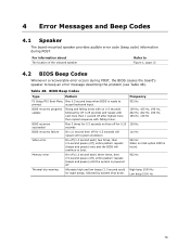
.... 932 Hz When no VGA option ROM is ready to prompt accept keyboard input 932 Hz BIOS recovery progress update Rising and falling tones with on then off for 0.25 139 Hz seconds BIOS recovery failure On 1.0 second then off for 0.5 seconds will continue to beep an error message describing...off 0.25 seconds and repeat with falling tones. 139 Hz, 165 Hz, 196 Hz, 262 Hz, 262 Hz, 196 Hz, 165 Hz, 139 Hz BIOS recovery succeeded Play 3 times for 0.5 seconds on 0.5 seconds followed by system shut down. 4 Error Messages and Beep Codes 4.1 Speaker The board-mounted speaker provides...
.... 932 Hz When no VGA option ROM is ready to prompt accept keyboard input 932 Hz BIOS recovery progress update Rising and falling tones with on then off for 0.25 139 Hz seconds BIOS recovery failure On 1.0 second then off for 0.5 seconds will continue to beep an error message describing...off 0.25 seconds and repeat with falling tones. 139 Hz, 165 Hz, 196 Hz, 262 Hz, 262 Hz, 196 Hz, 165 Hz, 139 Hz BIOS recovery succeeded Play 3 times for 0.5 seconds on 0.5 seconds followed by system shut down. 4 Error Messages and Beep Codes 4.1 Speaker The board-mounted speaker provides...

Technical Product Specification
Page 81
...0xFF For future use Boot Devices: Includes fixed media and removable media. Error Messages and Beep Codes 4.5 Port 80h POST Codes During the POST, the BIOS generates diagnostic progress codes (POST codes) to S5. Port 80h POST Code Ranges Range Subsystem 0x00 - 0x05 0x10, 0x20, 0x30, 0x40, 0x50 ...Figure 1. Table 51. Security (SEC) phase PEI phase pre MRC execution 0x21 - 0x29 0x2A - 0x2F 0x31 - 0x35 MRC Memory detection PEI phase post MRC execution Recovery 0x36 - 0x3F 0x41 - 0x4F 0x50 - 0x5F 0x60 - 0x6F 0x70 - 0x7F 0x80 - 0x8F 0x90 - 0x9F 0xA0 - 0xAF 0xB0 - 0xBF 0xC0 - 0xCF Platform...
...0xFF For future use Boot Devices: Includes fixed media and removable media. Error Messages and Beep Codes 4.5 Port 80h POST Codes During the POST, the BIOS generates diagnostic progress codes (POST codes) to S5. Port 80h POST Code Ranges Range Subsystem 0x00 - 0x05 0x10, 0x20, 0x30, 0x40, 0x50 ...Figure 1. Table 51. Security (SEC) phase PEI phase pre MRC execution 0x21 - 0x29 0x2A - 0x2F 0x31 - 0x35 MRC Memory detection PEI phase post MRC execution Recovery 0x36 - 0x3F 0x41 - 0x4F 0x50 - 0x5F 0x60 - 0x6F 0x70 - 0x7F 0x80 - 0x8F 0x90 - 0x9F 0xA0 - 0xAF 0xB0 - 0xBF 0xC0 - 0xCF Platform...

Technical Product Specification
Page 86
...SPD from memory DIMMs 23 Detecting presence of memory DIMMs 25 Configuring memory 28 Testing memory 34 Loading recovery capsule E4 Entered DXE phase 12 Starting application processor initialization 13 SMM initialization 50 Enumerating PCI buses ... the keyboard 90 Resetting keyboard 94 Clearing keyboard input buffer 95 Keyboard Self Test EB Calling Video BIOS 58 Resetting USB bus 5A Resetting PATA/SATA bus and all devices 92 Detecting the presence of...user input 01 INT 19 00 Ready to boot 86 Intel Desktop Board DH77DF Technical Product Specification Table 53.
...SPD from memory DIMMs 23 Detecting presence of memory DIMMs 25 Configuring memory 28 Testing memory 34 Loading recovery capsule E4 Entered DXE phase 12 Starting application processor initialization 13 SMM initialization 50 Enumerating PCI buses ... the keyboard 90 Resetting keyboard 94 Clearing keyboard input buffer 95 Keyboard Self Test EB Calling Video BIOS 58 Resetting USB bus 5A Resetting PATA/SATA bus and all devices 92 Detecting the presence of...user input 01 INT 19 00 Ready to boot 86 Intel Desktop Board DH77DF Technical Product Specification Table 53.


