
Smart Response Technology User Guide
Page 1
... SATA controller be set to RAID • Intel Rapid Storage Technology software 10.5 version release or later • Single Hard Disk Drive (HDD) or multiple HDD's in a single RAID volume • Solid State Drive (SSD) with a Solid State Drive (SSD) used as cache memory between the hard disk drive and system memory. System Requirements: For a system to support Intel Smart Response Technology it must have the following: • Intel® Z68/Z77/H77/Q77 Express Chipset-based desktop board • Intel® Core™ Processor...
... SATA controller be set to RAID • Intel Rapid Storage Technology software 10.5 version release or later • Single Hard Disk Drive (HDD) or multiple HDD's in a single RAID volume • Solid State Drive (SSD) with a Solid State Drive (SSD) used as cache memory between the hard disk drive and system memory. System Requirements: For a system to support Intel Smart Response Technology it must have the following: • Intel® Z68/Z77/H77/Q77 Express Chipset-based desktop board • Intel® Core™ Processor...

Technical Product Specification
Page 8
...3.5 Legacy USB Support 71 3.6 BIOS Updates 72 3.6.1 Language Support 72 3.6.2 Custom Splash Screen 73 3.7 BIOS Recovery 73 3.8 Boot Options 74 3.8.1 Optical Drive Boot 74 3.8.2 Network Boot 74 3.8.3 Booting Without Attached Devices 74 3.8.4 Changing the Default Boot Device During POST 74 3.9 Adjusting Boot Speed 75 3.9.1 Peripheral Selection and Configuration 75 3.9.2 BIOS Boot Optimizations 75 3.10 BIOS Security Features 76 3.11 BIOS Performance Features 77 4 Error Messages and Beep Codes 4.1 Speaker 79 4.2 BIOS Beep Codes 79 4.3 Front-panel Power LED Blink Codes 80 4.4 BIOS...
...3.5 Legacy USB Support 71 3.6 BIOS Updates 72 3.6.1 Language Support 72 3.6.2 Custom Splash Screen 73 3.7 BIOS Recovery 73 3.8 Boot Options 74 3.8.1 Optical Drive Boot 74 3.8.2 Network Boot 74 3.8.3 Booting Without Attached Devices 74 3.8.4 Changing the Default Boot Device During POST 74 3.9 Adjusting Boot Speed 75 3.9.1 Peripheral Selection and Configuration 75 3.9.2 BIOS Boot Optimizations 75 3.10 BIOS Security Features 76 3.11 BIOS Performance Features 77 4 Error Messages and Beep Codes 4.1 Speaker 79 4.2 BIOS Beep Codes 79 4.3 Front-panel Power LED Blink Codes 80 4.4 BIOS...

Technical Product Specification
Page 9
...* 5.0, e-Standby, and ErP Compliance 95 5.1.7 Regulatory Compliance Marks (Board Level 96 5.2 Battery Disposal Information 97 Figures 1. Connection Diagram for Front Panel USB 2.0 Headers 58 15. LAN Connector LED Locations 33 7. Major Board Components (Bottom 49 13. Major Board Components 13 2. Back Panel Audio Connectors 31 6. Component-side Connectors and Headers 47 12. Intel Desktop Board DH77DF China RoHS Material Self Declaration Table 92 Tables 1. Components Shown in Figure 11 48 16. Supported Memory Configurations 20 5.
...* 5.0, e-Standby, and ErP Compliance 95 5.1.7 Regulatory Compliance Marks (Board Level 96 5.2 Battery Disposal Information 97 Figures 1. Connection Diagram for Front Panel USB 2.0 Headers 58 15. LAN Connector LED Locations 33 7. Major Board Components (Bottom 49 13. Major Board Components 13 2. Back Panel Audio Connectors 31 6. Component-side Connectors and Headers 47 12. Intel Desktop Board DH77DF China RoHS Material Self Declaration Table 92 Tables 1. Components Shown in Figure 11 48 16. Supported Memory Configurations 20 5.
Technical Product Specification
Page 10
.... S/PDIF Header 51 23. PCI Express Full-/Half-Mini Card Connector 53 28. Acceptable Drives/Media Types for a One-Color Power LED 57 34. Port 80h POST Codes 82 53. Front Panel USB 3.0 Connector 51 21. Back Panel CIR Emitter (Output) Header 52 26. Processor Core Power Connector 55 31. BIOS Error Messages 80 51. SATA Connectors 51 22. Tcontrol Values for Components 66 42. Chassis Intrusion Header 52 24. HTPC Header 54 30. BIOS Setup Configuration Jumper Settings 60 37. Fan Header Current Capability...
.... S/PDIF Header 51 23. PCI Express Full-/Half-Mini Card Connector 53 28. Acceptable Drives/Media Types for a One-Color Power LED 57 34. Port 80h POST Codes 82 53. Front Panel USB 3.0 Connector 51 21. Back Panel CIR Emitter (Output) Header 52 26. Processor Core Power Connector 55 31. BIOS Error Messages 80 51. SATA Connectors 51 22. Tcontrol Values for Components 66 42. Chassis Intrusion Header 52 24. HTPC Header 54 30. BIOS Setup Configuration Jumper Settings 60 37. Fan Header Current Capability...

Technical Product Specification
Page 12
... internal SATA 3.0 Gb/s interfaces through the Intel H77 Express Chipset with Intel Rapid Storage Technology RAID support (black) ― One internal mSATA port (PCI Express Full-/Half-Mini Card slot) ― One back panel eSATA port (red) • One PCI Express 3.0 x16 add-in card connector • One PCI Express Full-/Half-Mini Card slot with support for mSATA Note: PCI Express 3.0 is only supported by 3rd generation Intel Core processor family processors • Intel® BIOS resident in the SPI Flash device • Support for Advanced Configuration and Power Interface (ACPI), Plug...
... internal SATA 3.0 Gb/s interfaces through the Intel H77 Express Chipset with Intel Rapid Storage Technology RAID support (black) ― One internal mSATA port (PCI Express Full-/Half-Mini Card slot) ― One back panel eSATA port (red) • One PCI Express 3.0 x16 add-in card connector • One PCI Express Full-/Half-Mini Card slot with support for mSATA Note: PCI Express 3.0 is only supported by 3rd generation Intel Core processor family processors • Intel® BIOS resident in the SPI Flash device • Support for Advanced Configuration and Power Interface (ACPI), Plug...

Technical Product Specification
Page 20
... 4. lists the supported DIMM configurations. If non-SPD memory is installed, the BIOS will attempt to correctly configure the memory settings, but performance and reliability may not function under the determined frequency. Tested Memory Refer to accurately configure memory settings for optimum performance. Intel Desktop Board DH77DF Technical Product Specification 1.4 System Memory The board has two DIMM sockets and supports the following memory features: • 1.5 V DDR3 SDRAM DIMMs with gold plated contacts, with the option...
... 4. lists the supported DIMM configurations. If non-SPD memory is installed, the BIOS will attempt to correctly configure the memory settings, but performance and reliability may not function under the determined frequency. Tested Memory Refer to accurately configure memory settings for optimum performance. Intel Desktop Board DH77DF Technical Product Specification 1.4 System Memory The board has two DIMM sockets and supports the following memory features: • 1.5 V DDR3 SDRAM DIMMs with gold plated contacts, with the option...
Technical Product Specification
Page 25
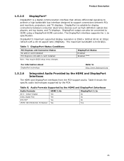
... for display connections between PCs and monitors, projectors, and TV displays. DisplayPort Status Conditions PCI Express x16 Connector Status No add-in card installed PCI Express x16 add-in card installed Note: May require BIOS setup menu changes. Table 8 shows the specific audio technologies supported by the HDMI and DisplayPort Interfaces Audio Formats HDMI 1.4a DisplayPort 1.1a AC-3 - DisplayPort output can also be converted to http://www.displayport.org 1.5.2.6 Integrated Audio Provided by the HDMI and...
... for display connections between PCs and monitors, projectors, and TV displays. DisplayPort Status Conditions PCI Express x16 Connector Status No add-in card installed PCI Express x16 add-in card installed Note: May require BIOS setup menu changes. Table 8 shows the specific audio technologies supported by the HDMI and DisplayPort Interfaces Audio Formats HDMI 1.4a DisplayPort 1.1a AC-3 - DisplayPort output can also be converted to http://www.displayport.org 1.5.2.6 Integrated Audio Provided by the HDMI and...

Technical Product Specification
Page 27
... the Intel H77 Express Chipset with Intel® Rapid Storage Technology RAID support (blue) • Two internal Serial ATA (SATA) 3.0 Gb/s interfaces through the Intel H77 Express Chipset with Intel Rapid Storage Technology RAID support (black) • One internal mSATA port (PCI Express Full-/Half-Mini Card slot) • One back panel eSATA port (red) The PCH provides independent SATA ports with low-voltage power connectors. The PCH also supports several optional sections of 6.0 Gb/s for two ports and 3.0 Gb/s for five ports. In legacy mode, standard IDE I/O and...
... the Intel H77 Express Chipset with Intel® Rapid Storage Technology RAID support (blue) • Two internal Serial ATA (SATA) 3.0 Gb/s interfaces through the Intel H77 Express Chipset with Intel Rapid Storage Technology RAID support (black) • One internal mSATA port (PCI Express Full-/Half-Mini Card slot) • One back panel eSATA port (red) The PCH provides independent SATA ports with low-voltage power connectors. The PCH also supports several optional sections of 6.0 Gb/s for two ports and 3.0 Gb/s for five ports. In legacy mode, standard IDE I/O and...
Technical Product Specification
Page 28
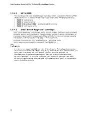
... to install separate RAID drivers using the F6 switch in the BIOS. Intel Desktop Board DH77DF Technical Product Specification 1.5.4.1 SATA RAID The board supports Intel Rapid Storage Technology which provides the following RAID (Redundant Array of having HDDs for maximum storage capacity with improved power savings. data striping and mirroring • RAID 5 - Also, during installation. It allows configuration of a computer system with the advantage of Independent Drives) levels via the Intel H77 Express Chipset: • RAID 0 - data mirroring • RAID 0+1 (or RAID...
... to install separate RAID drivers using the F6 switch in the BIOS. Intel Desktop Board DH77DF Technical Product Specification 1.5.4.1 SATA RAID The board supports Intel Rapid Storage Technology which provides the following RAID (Redundant Array of having HDDs for maximum storage capacity with improved power savings. data striping and mirroring • RAID 5 - Also, during installation. It allows configuration of a computer system with the advantage of Independent Drives) levels via the Intel H77 Express Chipset: • RAID 0 - data mirroring • RAID 0+1 (or RAID...
Technical Product Specification
Page 29
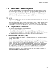
... to connect to Intel Desktop Boards for example, the date and time) might not be notified during the POST. When the voltage drops below a certain level, the BIOS Setup program settings stored in order to speak the infrared communication language of three years. The clock is simply a high pass input which the PC can use to emulate "learned" infrared commands in CMOS RAM (for...
... to connect to Intel Desktop Boards for example, the date and time) might not be notified during the POST. When the voltage drops below a certain level, the BIOS Setup program settings stored in order to speak the infrared communication language of three years. The clock is simply a high pass input which the PC can use to emulate "learned" infrared commands in CMOS RAM (for...
Technical Product Specification
Page 32
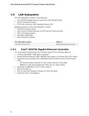
Intel Desktop Board DH77DF Technical Product Specification 1.9 LAN Subsystem The LAN subsystem consists of the following: • Intel 82579V Gigabit Ethernet Controller (10/100/1000 Mb/s) • Intel H77 Express Chipset • RJ-45 LAN connector with integrated status LEDs Additional features of the LAN subsystem include: • CSMA/CD protocol engine • LAN connect interface between the PCH and the LAN controller • ACPI technology support • LAN wake capabilities • LAN subsystem software For information about...
Intel Desktop Board DH77DF Technical Product Specification 1.9 LAN Subsystem The LAN subsystem consists of the following: • Intel 82579V Gigabit Ethernet Controller (10/100/1000 Mb/s) • Intel H77 Express Chipset • RJ-45 LAN connector with integrated status LEDs Additional features of the LAN subsystem include: • CSMA/CD protocol engine • LAN connect interface between the PCH and the LAN controller • ACPI technology support • LAN wake capabilities • LAN subsystem software For information about...

Technical Product Specification
Page 36
...; Power connector ⎯ Fan headers ⎯ LAN wake capabilities ⎯ Instantly Available PC technology ⎯ Wake from USB ⎯ PCI Express WAKE# signal support ⎯ Wake from Consumer IR ⎯ Wake from S5 ⎯ +5 V Standby Power Indicator LED 1.11.1 ACPI ACPI gives the operating system direct control over the power management and Plug and Play functions of ACPI with an ACPI-aware operating system. working state) Soft-off (ACPI G2/G5 - working state) On (ACPI G0 - Intel Desktop Board DH77DF Technical Product Specification...
...; Power connector ⎯ Fan headers ⎯ LAN wake capabilities ⎯ Instantly Available PC technology ⎯ Wake from USB ⎯ PCI Express WAKE# signal support ⎯ Wake from Consumer IR ⎯ Wake from S5 ⎯ +5 V Standby Power Indicator LED 1.11.1 ACPI ACPI gives the operating system direct control over the power management and Plug and Play functions of ACPI with an ACPI-aware operating system. working state) Soft-off (ACPI G2/G5 - working state) On (ACPI G0 - Intel Desktop Board DH77DF Technical Product Specification...

Technical Product Specification
Page 58
Intel Desktop Board DH77DF Technical Product Specification 2.2.3.6 Front Panel USB 2.0 Headers Figure 14 is fused. • Use only a front panel USB connector that conforms to the USB 2.0 specification for high-speed USB devices. Figure 14. Connection Diagram for the front panel USB 2.0 headers. NOTE • The +5 V DC power on the USB headers is a connection diagram for Front Panel USB 2.0 Headers 58
Intel Desktop Board DH77DF Technical Product Specification 2.2.3.6 Front Panel USB 2.0 Headers Figure 14 is fused. • Use only a front panel USB connector that conforms to the USB 2.0 specification for high-speed USB devices. Figure 14. Connection Diagram for the front panel USB 2.0 headers. NOTE • The +5 V DC power on the USB headers is a connection diagram for Front Panel USB 2.0 Headers 58
Technical Product Specification
Page 69
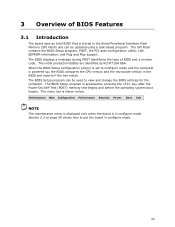
... is accessed by pressing the key after the Power-On Self-Test (POST) memory test begins and before the operating system boot begins. The menu bar is in configure mode. Maintenance Main Configuration Performance Security Power Boot Exit NOTE The maintenance menu is displayed only when the board is shown below. 3 Overview of BIOS and a revision code. The SPI Flash contains the BIOS Setup program, POST, the PCI auto-configuration utility, LAN EEPROM information, and Plug and Play support.
... is accessed by pressing the key after the Power-On Self-Test (POST) memory test begins and before the operating system boot begins. The menu bar is in configure mode. Maintenance Main Configuration Performance Security Power Boot Exit NOTE The maintenance menu is displayed only when the board is shown below. 3 Overview of BIOS and a revision code. The SPI Flash contains the BIOS Setup program, POST, the PCI auto-configuration utility, LAN EEPROM information, and Plug and Play support.

Technical Product Specification
Page 70
PCI Express devices may be available for menu screens. Any interrupts set to Available in Setup are considered to be onboard or add-in card. 70 tion Performance Clears passwords and displays processor information Displays processor and memory configuration Configures advanced features available through the chipset Configures Memory, Bus and Processor overrides Security Sets passwords and security features Power Configures power management features and power supply controls Boot Selects boot options Exit Saves or discards changes to configure the system. BIOS Setup Program ...
PCI Express devices may be available for menu screens. Any interrupts set to Available in Setup are considered to be onboard or add-in card. 70 tion Performance Clears passwords and displays processor information Displays processor and memory configuration Configures advanced features available through the chipset Configures Memory, Bus and Processor overrides Security Sets passwords and security features Power Configures power management features and power supply controls Boot Selects boot options Exit Saves or discards changes to configure the system. BIOS Setup Program ...

Technical Product Specification
Page 71
... memory size, cache size, and processor speed • Dynamic data, such as follows: 1. When you to use SMBIOS. Additional USB legacy feature options can be used to access the BIOS Setup program, and to enter and configure the BIOS Setup program and the maintenance menu. 4. POST begins. 3. After the operating system loads the USB drivers, all legacy and non-legacy USB devices are not yet available. The operating system loads. Legacy USB support operates as event detection and error logging Non-Plug...
... memory size, cache size, and processor speed • Dynamic data, such as follows: 1. When you to use SMBIOS. Additional USB legacy feature options can be used to access the BIOS Setup program, and to enter and configure the BIOS Setup program and the maintenance menu. 4. POST begins. 3. After the operating system loads the USB drivers, all legacy and non-legacy USB devices are not yet available. The operating system loads. Legacy USB support operates as event detection and error logging Non-Plug...

Technical Product Specification
Page 74
...El Torito bootable CD-ROM format specification. Intel Desktop Board DH77DF Technical Product Specification 3.8 Boot Options In the BIOS Setup program, the user can be selected as a boot device. Table 46 lists the boot device menu options. Boot devices are not present: • Video adapter • Keyboard • Mouse 3.8.4 Changing the Default Boot Device During POST Pressing the key during POST automatically forces booting from a hard drive, optical drive, removable drive, or the network. Under the Boot menu in compliance to boot from the onboard LAN or a network add-in...
...El Torito bootable CD-ROM format specification. Intel Desktop Board DH77DF Technical Product Specification 3.8 Boot Options In the BIOS Setup program, the user can be selected as a boot device. Table 46 lists the boot device menu options. Boot devices are not present: • Video adapter • Keyboard • Mouse 3.8.4 Changing the Default Boot Device During POST Pressing the key during POST automatically forces booting from a hard drive, optical drive, removable drive, or the network. Under the Boot menu in compliance to boot from the onboard LAN or a network add-in...
Technical Product Specification
Page 76
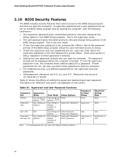
..., use different passwords for a password. Users have access to Setup respective to Enter Setup None Password During Boot None Supervisor None User User Supervisor or Supervisor or user user 76 This is booted. Intel Desktop Board DH77DF Technical Product Specification 3.10 BIOS Security Features The BIOS includes security features that restrict access to view and change all Setup options. Supervisor and User Password Functions Password Supervisor Set Mode User Mode Setup Options Neither Supervisor only User only Can change all options (Note) Can change all options...
..., use different passwords for a password. Users have access to Setup respective to Enter Setup None Password During Boot None Supervisor None User User Supervisor or Supervisor or user user 76 This is booted. Intel Desktop Board DH77DF Technical Product Specification 3.10 BIOS Security Features The BIOS includes security features that restrict access to view and change all Setup options. Supervisor and User Password Functions Password Supervisor Set Mode User Mode Setup Options Neither Supervisor only User only Can change all options (Note) Can change all options...

Technical Product Specification
Page 80
... CMOS checksum is complete. If no VGA option ROM is powered off . Replace the battery soon. Run Setup to boot. 80 Memory Size Decreased Memory size has decreased since the last boot. No Boot Device Available System did not find a device to reset values. Video error On-off (1.0 second each ) three times, then 2.5-second pause (off), entire pattern repeats (blinks and pause) until the BIOS update is incorrect. Intel Desktop Board DH77DF Technical Product Specification 4.3 Front-panel Power LED Blink Codes...
... CMOS checksum is complete. If no VGA option ROM is powered off . Replace the battery soon. Run Setup to boot. 80 Memory Size Decreased Memory size has decreased since the last boot. No Boot Device Available System did not find a device to reset values. Video error On-off (1.0 second each ) three times, then 2.5-second pause (off), entire pattern repeats (blinks and pause) until the BIOS update is incorrect. Intel Desktop Board DH77DF Technical Product Specification 4.3 Front-panel Power LED Blink Codes...

Technical Product Specification
Page 81
... driver CPU Initialization (PEI, DXE, SMM) I /O port 80h. Start with the Low Pin Count (LPC) Debug connector. Not that can decode the port and display the contents on a medium such as a seven-segment display. Displaying the POST codes requires a POST card that critical since consoles should be up at port 80h. S1, 0x20 - For future use Boot Devices: Includes fixed media and removable media. Error Messages and Beep Codes 4.5 Port 80h POST Codes During the POST...
... driver CPU Initialization (PEI, DXE, SMM) I /O port 80h. Start with the Low Pin Count (LPC) Debug connector. Not that can decode the port and display the contents on a medium such as a seven-segment display. Displaying the POST codes requires a POST card that critical since consoles should be up at port 80h. S1, 0x20 - For future use Boot Devices: Includes fixed media and removable media. Error Messages and Beep Codes 4.5 Port 80h POST Codes During the POST...


