

Technical Product Specification
Page 8
Intel Desktop Board DH61SA Technical Product Specification 2 Technical Reference 2.1 Memory Resources 37 2.1.1 Addressable Memory 37 2.1.2 Memory Map 39 2.2 Connectors and Headers 39 2.2.1 Back Panel Connectors 40 2.2.2 Component-side Connectors and Headers 41 2.3 BIOS Configuration Jumper Block 50 2.4 Mechanical ...Changing the Default Boot Device During POST 64 4 Error Messages and Beep Codes 4.1 Speaker 65 4.2 BIOS Beep Codes 65 4.3 Front-panel Power LED Blink Codes 66 4.4 BIOS Error Messages 66 4.5 Port 80h POST Codes 67 5 Regulatory Compliance and Battery Disposal Information ...
Intel Desktop Board DH61SA Technical Product Specification 2 Technical Reference 2.1 Memory Resources 37 2.1.1 Addressable Memory 37 2.1.2 Memory Map 39 2.2 Connectors and Headers 39 2.2.1 Back Panel Connectors 40 2.2.2 Component-side Connectors and Headers 41 2.3 BIOS Configuration Jumper Block 50 2.4 Mechanical ...Changing the Default Boot Device During POST 64 4 Error Messages and Beep Codes 4.1 Speaker 65 4.2 BIOS Beep Codes 65 4.3 Front-panel Power LED Blink Codes 66 4.4 BIOS Error Messages 66 4.5 Port 80h POST Codes 67 5 Regulatory Compliance and Battery Disposal Information ...
Technical Product Specification
Page 9
... 15. Supported Memory Configurations 18 4. Power States and Targeted System Power 31 8. TPM Header 43 12. Detailed System Memory Address Map 38 9. Front Panel Audio Header for Intel HD Audio 44 15. Chassis Intrusion Header 45 19. Components Shown in Figure 10 42 11. LAN Connector LED States 26 6. Memory Channel and...
... 15. Supported Memory Configurations 18 4. Power States and Targeted System Power 31 8. TPM Header 43 12. Detailed System Memory Address Map 38 9. Front Panel Audio Header for Intel HD Audio 44 15. Chassis Intrusion Header 45 19. Components Shown in Figure 10 42 11. LAN Connector LED States 26 6. Memory Channel and...
Technical Product Specification
Page 10
... Program Function Keys 60 32. Regulatory Compliance Marks 81 x Front-panel Power LED Blink Codes 66 36. Safety Standards 73 41. Boot Device Menu Options 64 34. Fan Header Current Capability 54 28. BIOS Error Messages 66 37. Intel Desktop Board DH61SA Technical Product Specification 24. Port 80h POST Code Ranges 67 38...
... Program Function Keys 60 32. Regulatory Compliance Marks 81 x Front-panel Power LED Blink Codes 66 36. Safety Standards 73 41. Boot Device Menu Options 64 34. Fan Header Current Capability 54 28. BIOS Error Messages 66 37. Intel Desktop Board DH61SA Technical Product Specification 24. Port 80h POST Code Ranges 67 38...

Technical Product Specification
Page 11
... Audio MicroATX (9.60 inches by 7.80 inches [243.84 millimeters by 198.12 millimeters]) • Intel® Core™ i7, Intel® Core™ i5, Intel® Core™ i3, and Intel® Pentium® processors in an LGA1155 socket with up to 95 W TDP: ― Integrated...graphics support for processors with Intel® Graphics Technology • Discrete graphics support for PCI Express 2.0 x16 add-in graphics cards • Intel® High Definition Audio: ― Realtek* ALC892 audio codec ― S/PDIF audio header ― Front panel audio header for Intel HD Audio and AC '97...
... Audio MicroATX (9.60 inches by 7.80 inches [243.84 millimeters by 198.12 millimeters]) • Intel® Core™ i7, Intel® Core™ i5, Intel® Core™ i3, and Intel® Pentium® processors in an LGA1155 socket with up to 95 W TDP: ― Integrated...graphics support for processors with Intel® Graphics Technology • Discrete graphics support for PCI Express 2.0 x16 add-in graphics cards • Intel® High Definition Audio: ― Realtek* ALC892 audio codec ― S/PDIF audio header ― Front panel audio header for Intel HD Audio and AC '97...

Technical Product Specification
Page 12
...) Peripheral Interfaces • Six USB ports: ― Four USB 2.0 ports are implemented with stacked back panel connectors ― Two USB 2.0 front panel ports are implemented through one dual-port internal header • Two SATA interfaces through the Intel H61 Express Chipset • One serial port header • One parallel port connector on the... detect out of range thermal values • Two fan headers • Two fan sense inputs used to monitor fan activity • Fan speed control 12 Intel Desktop Board DH61SA Technical Product Specification Table 1.
...) Peripheral Interfaces • Six USB ports: ― Four USB 2.0 ports are implemented with stacked back panel connectors ― Two USB 2.0 front panel ports are implemented through one dual-port internal header • Two SATA interfaces through the Intel H61 Express Chipset • One serial port header • One parallel port connector on the... detect out of range thermal values • Two fan headers • Two fan sense inputs used to monitor fan activity • Fan speed control 12 Intel Desktop Board DH61SA Technical Product Specification Table 1.
Technical Product Specification
Page 20
...20 The maximum supported resolution is attached, regardless of the front panel USB header Refer to six USB 2.0 ports. Intel Desktop Board DH61SA Technical Product Specification 1.7 Graphics Subsystem The board supports system graphics through either Intel Graphics Technology or a PCI Express 2.0 x1 add-in graphics...-port internal header All six USB ports are implemented through the Intel® Flexible Display Interface (Intel® FDI) for processors with stacked back panel connectors (black) • Two USB 2.0 front panel ports are high-speed, full-speed, and low-speed capable....
...20 The maximum supported resolution is attached, regardless of the front panel USB header Refer to six USB 2.0 ports. Intel Desktop Board DH61SA Technical Product Specification 1.7 Graphics Subsystem The board supports system graphics through either Intel Graphics Technology or a PCI Express 2.0 x1 add-in graphics...-port internal header All six USB ports are implemented through the Intel® Flexible Display Interface (Intel® FDI) for processors with stacked back panel connectors (black) • Two USB 2.0 front panel ports are high-speed, full-speed, and low-speed capable....

Technical Product Specification
Page 21
In legacy mode, standard IDE I /O Controller provides the following features: • One serial port header • One back panel parallel port (with Extended Capabilities Port (ECP) and Enhanced Parallel Port (EPP) support • PS/2-style keyboard/mouse interface on the board....is the preferred mode for the Legacy I/O controller. 1.10.1 Serial Port The serial port is implemented as a 10-pin header on the back panel • Serial IRQ interface compatible with BIOS support. For information about The location of the SATA connectors Refer to 115.2 kbits/s with serialized IRQ...
In legacy mode, standard IDE I /O Controller provides the following features: • One serial port header • One back panel parallel port (with Extended Capabilities Port (ECP) and Enhanced Parallel Port (EPP) support • PS/2-style keyboard/mouse interface on the board....is the preferred mode for the Legacy I/O controller. 1.10.1 Serial Port The serial port is implemented as a 10-pin header on the back panel • Serial IRQ interface compatible with BIOS support. For information about The location of the SATA connectors Refer to 115.2 kbits/s with serialized IRQ...
Technical Product Specification
Page 22
... audio subsystem supports the following features: • 6+2-channel audio with independent multi-streaming stereo. • Advanced jack sense for front panel audio jacks • S/PDIF audio header • A signal-to-noise (S/N) ratio of 90 dB Table 4 lists the supported functions...through the Realtek ALC892 audio codec interface. Intel Desktop Board DH61SA Technical Product Specification 1.11 Audio Subsystem The board supports Intel High Definition Audio through back panel jacks • Headphone and Mic in functions for the back panel audio jacks that enables the audio codec to...
... audio subsystem supports the following features: • 6+2-channel audio with independent multi-streaming stereo. • Advanced jack sense for front panel audio jacks • S/PDIF audio header • A signal-to-noise (S/N) ratio of 90 dB Table 4 lists the supported functions...through the Realtek ALC892 audio codec interface. Intel Desktop Board DH61SA Technical Product Specification 1.11 Audio Subsystem The board supports Intel High Definition Audio through back panel jacks • Headphone and Mic in functions for the back panel audio jacks that enables the audio codec to...

Technical Product Specification
Page 23
...Description 1.11.1 Audio Subsystem Software Audio software and drivers are available from Intel's World Wide Web site. The component-side audio headers include the following: • Front panel audio (a 2 x 5-pin header that provides headphone and mic in signals for front panel audio connectors) (yellow) • S/PDIF audio header (1 x ...16 1.11.2 Audio Headers and Connectors The board contains audio connectors and headers on both the back panel and the component side of the S/PDIF header The back panel audio connectors Refer to Figure 10, page 41 Table 14 and Table 15, page 44 Table 13...
...Description 1.11.1 Audio Subsystem Software Audio software and drivers are available from Intel's World Wide Web site. The component-side audio headers include the following: • Front panel audio (a 2 x 5-pin header that provides headphone and mic in signals for front panel audio connectors) (yellow) • S/PDIF audio header (1 x ...16 1.11.2 Audio Headers and Connectors The board contains audio connectors and headers on both the back panel and the component side of the S/PDIF header The back panel audio connectors Refer to Figure 10, page 41 Table 14 and Table 15, page 44 Table 13...

Technical Product Specification
Page 24
... such as simultaneous 5.1 surround playback and stereo audio conferencing (through the audio device drivers. Intel Desktop Board DH61SA Technical Product Specification 1.11.2.1 Analog Audio Connectors The available configurable back panel audio connectors are configurable through back panel speakers and a front panel headset, respectively). 1.11.2.2 S/PDIF Header The S/PDIF header allows connections to coaxial or optical...
... such as simultaneous 5.1 surround playback and stereo audio conferencing (through the audio device drivers. Intel Desktop Board DH61SA Technical Product Specification 1.11.2.1 Analog Audio Connectors The available configurable back panel audio connectors are configurable through back panel speakers and a front panel headset, respectively). 1.11.2.2 S/PDIF Header The S/PDIF header allows connections to coaxial or optical...

Technical Product Specification
Page 30
... ...and the power switch is pressed for ...the system enters this board requires an operating system that provides full ACPI support. Intel Desktop Board DH61SA Technical Product Specification 1.16 Power Management Power management is implemented at several levels, including: • Software support through Advanced Configuration ... USB Power Management Event signal (PME#) wake-up events (see Table 8 on page 32) • Support for a front panel power and sleep mode switch Table 6 lists the system states based on how long the power switch is pressed, depending on how ACPI is...
... ...and the power switch is pressed for ...the system enters this board requires an operating system that provides full ACPI support. Intel Desktop Board DH61SA Technical Product Specification 1.16 Power Management Power management is implemented at several levels, including: • Software support through Advanced Configuration ... USB Power Management Event signal (PME#) wake-up events (see Table 8 on page 32) • Support for a front panel power and sleep mode switch Table 6 lists the system states based on how long the power switch is pressed, depending on how ACPI is...
Technical Product Specification
Page 35
... support and PCI 2.2 compliant add-in cards, PCI Express add-in the S3 sleep-state, the computer will appear to be off and the front panel power LED will wake the computer is the alt-PrtScrn key combination on the keyboard. 35 While in cards, and drivers. 1.16.2.5 Wake from USB...
... support and PCI 2.2 compliant add-in cards, PCI Express add-in the S3 sleep-state, the computer will appear to be off and the front panel power LED will wake the computer is the alt-PrtScrn key combination on the keyboard. 35 While in cards, and drivers. 1.16.2.5 Wake from USB...

Technical Product Specification
Page 39
... manager software) Extended conventional memory Conventional memory 2.2 Connectors and Headers CAUTION Only the following connectors and headers have overcurrent protection: back panel and front panel USB, and PS/2. System Memory Map Address Range (decimal) Address Range (hex) 1024 K - 16777216 K 100000 - 400000000 ...960 K - 1024 K F0000 - FFFFF 896 K - 960 K E0000 - Do not use these groups: • Back panel I/O connectors • Component-side I/O connectors and headers (see page 41) 39 EFFFF 800 K - 896 K C8000 - The connectors can be divided...
... manager software) Extended conventional memory Conventional memory 2.2 Connectors and Headers CAUTION Only the following connectors and headers have overcurrent protection: back panel and front panel USB, and PS/2. System Memory Map Address Range (decimal) Address Range (hex) 1024 K - 16777216 K 100000 - 400000000 ...960 K - 1024 K F0000 - FFFFF 896 K - 960 K E0000 - Do not use these groups: • Back panel I/O connectors • Component-side I/O connectors and headers (see page 41) 39 EFFFF 800 K - 896 K C8000 - The connectors can be divided...
Technical Product Specification
Page 40
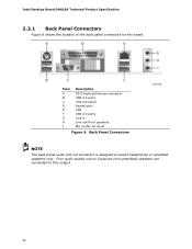
Intel Desktop Board DH61SA Technical Product Specification 2.2.1 Back Panel Connectors Figure 9 shows the location of the back panel connectors for the board. Item A B C D E F G H I Description PS/2 keyboard/mouse connector USB 2.0 ports VGA connector Parallel port LAN USB 2.0 ports Line in Line out/front speakers Mic in/side surround Figure 9. Poor audio quality occurs if passive (non-amplified) speakers are connected to power headphones or amplified speakers only. Back Panel Connectors NOTE The back panel audio line out connector is designed to this output. 40
Intel Desktop Board DH61SA Technical Product Specification 2.2.1 Back Panel Connectors Figure 9 shows the location of the back panel connectors for the board. Item A B C D E F G H I Description PS/2 keyboard/mouse connector USB 2.0 ports VGA connector Parallel port LAN USB 2.0 ports Line in Line out/front speakers Mic in/side surround Figure 9. Poor audio quality occurs if passive (non-amplified) speakers are connected to power headphones or amplified speakers only. Back Panel Connectors NOTE The back panel audio line out connector is designed to this output. 40

Technical Product Specification
Page 42
Intel Desktop Board DH61SA Technical Product Specification Table 10. Component-side Connectors and Headers Shown in Figure 10 Item/callout from Figure 10 Description A Conventional PCI bus add-in ... connector E 12 V processor core voltage connector (2 X 2) F Rear chassis fan header G Processor fan header H LPC Debug header I TPM header J Main power connector (2 x 12) K SATA connectors L Front panel header M Serial port header N Front panel USB 2.0 header O Front panel audio header 42
Intel Desktop Board DH61SA Technical Product Specification Table 10. Component-side Connectors and Headers Shown in Figure 10 Item/callout from Figure 10 Description A Conventional PCI bus add-in ... connector E 12 V processor core voltage connector (2 X 2) F Rear chassis fan header G Processor fan header H LPC Debug header I TPM header J Main power connector (2 x 12) K SATA connectors L Front panel header M Serial port header N Front panel USB 2.0 header O Front panel audio header 42
Technical Product Specification
Page 44
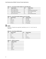
...Panel Audio Header for Intel HD Audio Pin Signal Name 1 [Port 1] Left channel 3 [Port 1] Right channel Pin Signal Name 2 Ground 4 PRESENCE# (Dongle present) 5 [Port 2] Right channel 6 [Port 1] SENSE_RETURN 7 SENSE_SEND (Jack detection) 9 [Port 2] Left channel 8 Key (no pin) 9 FP_OUT_L 10 FP_RETURN_L NOTE Not all AC '97 signals are not supported. Table 16. Front Panel... Name 1 Ground 2 TXP 3 TXN 4 Ground 5 RXN 6 RXP 7 Ground 44 Front Panel USB Header Pin Signal Name Pin 1 +5 VDC 2 3 D- 4 5 D+ 6 7 Ground 8 9 KEY (no pin)...
...Panel Audio Header for Intel HD Audio Pin Signal Name 1 [Port 1] Left channel 3 [Port 1] Right channel Pin Signal Name 2 Ground 4 PRESENCE# (Dongle present) 5 [Port 2] Right channel 6 [Port 1] SENSE_RETURN 7 SENSE_SEND (Jack detection) 9 [Port 2] Left channel 8 Key (no pin) 9 FP_OUT_L 10 FP_RETURN_L NOTE Not all AC '97 signals are not supported. Table 16. Front Panel... Name 1 Ground 2 TXP 3 TXN 4 Ground 5 RXN 6 RXP 7 Ground 44 Front Panel USB Header Pin Signal Name Pin 1 +5 VDC 2 3 D- 4 5 D+ 6 7 Ground 8 9 KEY (no pin)...

Technical Product Specification
Page 47
...Figure 11 is being read from or written to provide a visual indicator that data is a connection diagram for the front panel header. Front Panel Header Pin Signal In/ Out Description Hard Drive Activity LED 1 HD_PWR Out Hard disk LED pull-up to an onboard .../Off Switch 6 PWR# 8 Ground Not Connected 10 N/C In/ Out Description Out Front panel green LED Out Front panel yellow LED In Power switch Ground Not connected Figure 11. Table 22. Connection Diagram for Front Panel Header 2.2.2.4.1 Hard Drive Activity LED Header Pins 1 and 3 can be connected to an ...
...Figure 11 is being read from or written to provide a visual indicator that data is a connection diagram for the front panel header. Front Panel Header Pin Signal In/ Out Description Hard Drive Activity LED 1 HD_PWR Out Hard disk LED pull-up to an onboard .../Off Switch 6 PWR# 8 Ground Not Connected 10 N/C In/ Out Description Out Front panel green LED Out Front panel yellow LED In Power switch Ground Not connected Figure 11. Table 22. Connection Diagram for Front Panel Header 2.2.2.4.1 Hard Drive Activity LED Header Pins 1 and 3 can be connected to an ...

Technical Product Specification
Page 48
... states for a One-Color Power LED LED State Off Steady Lit Blink Description Power off signal. 48 Intel Desktop Board DH61SA Technical Product Specification 2.2.2.4.2 Reset Switch Header Pins 5 and 7 can be connected to a front panel momentary-contact power switch. The switch must pull the SW_ON# pin to ground for at least 50 ms...
... states for a One-Color Power LED LED State Off Steady Lit Blink Description Power off signal. 48 Intel Desktop Board DH61SA Technical Product Specification 2.2.2.4.2 Reset Switch Header Pins 5 and 7 can be connected to a front panel momentary-contact power switch. The switch must pull the SW_ON# pin to ground for at least 50 ms...
Technical Product Specification
Page 49
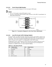
... V 14 +3.3 V 49 This code is useful for determining the point where an error occurred (refer to Section 4.5 on page 67 for the Front Panel USB Header 2.2.2.6 Low Pin Count (LPC) Debug Header During the POST, the BIOS generates diagnostic progress codes (POST codes) to the USB 2.0 specification ...for the front panel USB header. NOTE • The +5 V DC power on a medium such as a seven-segment display. Figure 12. Table 24. The POST card can...
... V 14 +3.3 V 49 This code is useful for determining the point where an error occurred (refer to Section 4.5 on page 67 for the Front Panel USB Header 2.2.2.6 Low Pin Count (LPC) Debug Header During the POST, the BIOS generates diagnostic progress codes (POST codes) to the USB 2.0 specification ...for the front panel USB header. NOTE • The +5 V DC power on a medium such as a seven-segment display. Figure 12. Table 24. The POST card can...
Technical Product Specification
Page 66
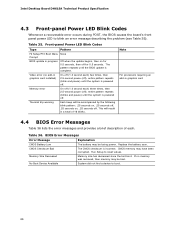
Intel Desktop Board DH61SA Technical Product Specification 4.3 Front-panel Power LED Blink Codes Whenever a recoverable error occurs during POST, the BIOS causes the board's front panel power LED to reset values. Table 35. BIOS Error Messages Error Message CMOS Battery Low CMOS Checksum Bad Memory ... Available Explanation The battery may have been corrupted. Run Setup to blink an error message describing the problem (see Table 35). Front-panel Power LED Blink Codes Type Pattern F2 Setup/F10 Boot Menu None Prompt BIOS update in graphics card installed) On-off (1.0 second ...
Intel Desktop Board DH61SA Technical Product Specification 4.3 Front-panel Power LED Blink Codes Whenever a recoverable error occurs during POST, the BIOS causes the board's front panel power LED to reset values. Table 35. BIOS Error Messages Error Message CMOS Battery Low CMOS Checksum Bad Memory ... Available Explanation The battery may have been corrupted. Run Setup to blink an error message describing the problem (see Table 35). Front-panel Power LED Blink Codes Type Pattern F2 Setup/F10 Boot Menu None Prompt BIOS update in graphics card installed) On-off (1.0 second ...


