

Technical Product Specification
Page 3
... USB current specifics were removed from the TPS • Updated Table 26 on page 55 to change the pinout of the board. 2. additional information has been added to the External Power Supply section. • Sections 1.10 Audio Subsystem and Section 2.2.3.1 Signal Tables for the Connectors and Headers have been updated to Table 31 on page 57 concerning LVDS single-channel output. • Added Section 3.8 Hard Disk Drive Password...
... USB current specifics were removed from the TPS • Updated Table 26 on page 55 to change the pinout of the board. 2. additional information has been added to the External Power Supply section. • Sections 1.10 Audio Subsystem and Section 2.2.3.1 Signal Tables for the Connectors and Headers have been updated to Table 31 on page 57 concerning LVDS single-channel output. • Added Section 3.8 Hard Disk Drive Password...
Technical Product Specification
Page 8
... Fan Header Current Capability 73 2.6.3 PCI Express* Add-in Card Considerations 73 2.7 Thermal Considerations 73 2.8 Reliability 76 2.9 Environmental 76 3 Overview of BIOS Features 3.1 Introduction 77 3.2 BIOS Flash Memory Organization 78 3.3 System Management BIOS (SMBIOS 79 3.4 Legacy USB Support 79 3.5 BIOS Updates 80 3.5.1 Language Support 80 3.5.2 Custom Splash Screen 81 3.6 BIOS Recovery 81 3.7 Boot Options 82 3.7.1 Optical Drive Boot 82 3.7.2 Network Boot 82 3.7.3 Booting Without Attached Devices 82 3.7.4 Changing the Default Boot Device During POST 82 3.8 Hard Disk...
... Fan Header Current Capability 73 2.6.3 PCI Express* Add-in Card Considerations 73 2.7 Thermal Considerations 73 2.8 Reliability 76 2.9 Environmental 76 3 Overview of BIOS Features 3.1 Introduction 77 3.2 BIOS Flash Memory Organization 78 3.3 System Management BIOS (SMBIOS 79 3.4 Legacy USB Support 79 3.5 BIOS Updates 80 3.5.1 Language Support 80 3.5.2 Custom Splash Screen 81 3.6 BIOS Recovery 81 3.7 Boot Options 82 3.7.1 Optical Drive Boot 82 3.7.2 Network Boot 82 3.7.3 Booting Without Attached Devices 82 3.7.4 Changing the Default Boot Device During POST 82 3.8 Hard Disk...
Technical Product Specification
Page 9
... Fan Headers 38 10. Connection Diagram for the Front Panel USB 2.0 Single-Port Header ....... 63 18. Location of Intel Desktop Board DH61AG 70 23. Localized High Temperature Zones 74 ix Detailed System Memory Address Map 46 12. Connectors and Headers (Bottom 51 15. Half-Height Back Panel I /O Shield 66 20. Board Dimensions 69 22. 3D View of the Jumper Block 67 21. Major Board Components (Top 15 2. Memory Channel and SO-DIMM Configuration 22 5. LAN Connector LED Locations 36 9. Connection Diagram...
... Fan Headers 38 10. Connection Diagram for the Front Panel USB 2.0 Single-Port Header ....... 63 18. Location of Intel Desktop Board DH61AG 70 23. Localized High Temperature Zones 74 ix Detailed System Memory Address Map 46 12. Connectors and Headers (Bottom 51 15. Half-Height Back Panel I /O Shield 66 20. Board Dimensions 69 22. 3D View of the Jumper Block 67 21. Major Board Components (Top 15 2. Memory Channel and SO-DIMM Configuration 22 5. LAN Connector LED Locations 36 9. Connection Diagram...
Technical Product Specification
Page 10
... Considerations for Intel HD Audio 52 17. Supported Memory Configurations 20 6. HDMI Port Status Conditions 24 7. Debug Header 64 39. Intel Desktop Board DH61AG Technical Product Specification Tables 1. Components Shown in Figure 13 50 15. Wake-up Devices and Events 41 13. Connectors and Headers Shown in Figure 2 17 5. Front Panel Audio Header for Components 75 43. Internal Stereo Speakers Header 53 21. SATA Connectors 54 25. HTPC Header 56 29. Front Panel Header 61 37. Fan Header Current Capability...
... Considerations for Intel HD Audio 52 17. Supported Memory Configurations 20 6. HDMI Port Status Conditions 24 7. Debug Header 64 39. Intel Desktop Board DH61AG Technical Product Specification Tables 1. Components Shown in Figure 13 50 15. Wake-up Devices and Events 41 13. Connectors and Headers Shown in Figure 2 17 5. Front Panel Audio Header for Components 75 43. Internal Stereo Speakers Header 53 21. SATA Connectors 54 25. HTPC Header 56 29. Front Panel Header 61 37. Fan Header Current Capability...
Technical Product Specification
Page 11
Boot Device Menu Options 82 49. BIOS Error Messages 88 53. Safety Standards 95 57. Supervisor and User Password Functions 85 50. Typical Port 80h POST Sequence 94 56. Port 80h POST Code Ranges 89 54. Regulatory Compliance Marks 103 xi Contents 47. Front-panel Power LED Blink Codes 88 52. EMC Regulations 99 58. Port 80h POST Codes 90 55. BIOS Beep Codes 87 51. AccepDrives/Media Types for BIOS Recovery 81 48.
Boot Device Menu Options 82 49. BIOS Error Messages 88 53. Safety Standards 95 57. Supervisor and User Password Functions 85 50. Typical Port 80h POST Sequence 94 56. Port 80h POST Code Ranges 89 54. Regulatory Compliance Marks 103 xi Contents 47. Front-panel Power LED Blink Codes 88 52. EMC Regulations 99 58. Port 80h POST Codes 90 55. BIOS Beep Codes 87 51. AccepDrives/Media Types for BIOS Recovery 81 48.

Technical Product Specification
Page 14
...; One internal mSATA port (PCI Express Full-Mini Card slot) • One PCI Express 2.0 x4 add-in card connector • One PCI Express Half-Mini Card slot • One PCI Express Full-/Half-Mini Card slot • Intel® BIOS resident in the Serial Peripheral Interface (SPI) Flash device • Support for Advanced Configuration and Power Interface (ACPI), Plug and Play, and System Management BIOS (SMBIOS) Gigabit (10/100/1000 Mbits/s) LAN subsystem using the Intel® 82579V Gigabit Ethernet Controller Legacy I/O Control Hardware Monitor Subsystem...
...; One internal mSATA port (PCI Express Full-Mini Card slot) • One PCI Express 2.0 x4 add-in card connector • One PCI Express Half-Mini Card slot • One PCI Express Full-/Half-Mini Card slot • Intel® BIOS resident in the Serial Peripheral Interface (SPI) Flash device • Support for Advanced Configuration and Power Interface (ACPI), Plug and Play, and System Management BIOS (SMBIOS) Gigabit (10/100/1000 Mbits/s) LAN subsystem using the Intel® 82579V Gigabit Ethernet Controller Legacy I/O Control Hardware Monitor Subsystem...

Technical Product Specification
Page 20
If non-SPD memory is installed, the BIOS will attempt to accurately configure memory settings for optimum performance. This allows the BIOS to read the SPD data and program the chipset to correctly configure the memory settings, but performance and reliability may not function under the determined frequency. Table 5 lists the supported SO-DIMM configurations. Supported Memory Configurations Raw Card Version SO-DIMM Capacity DRAM Device DRAM Technology Organization # of DRAM Devices 1 GB A 2 GB 1 Gb 2 Gb 64...
If non-SPD memory is installed, the BIOS will attempt to accurately configure memory settings for optimum performance. This allows the BIOS to read the SPD data and program the chipset to correctly configure the memory settings, but performance and reliability may not function under the determined frequency. Table 5 lists the supported SO-DIMM configurations. Supported Memory Configurations Raw Card Version SO-DIMM Capacity DRAM Device DRAM Technology Organization # of DRAM Devices 1 GB A 2 GB 1 Gb 2 Gb 64...

Technical Product Specification
Page 24
... is allocated based on a single cable. Table 6. Intel Desktop Board DH61AG Technical Product Specification 1.6.1.2 Video Memory Allocation Intel® Dynamic Video Memory Technology (DVMT) is returned to the operating system for use DVMT, graphics memory is compatible with the HDMI 1.4 specification. When memory is no longer needed by an application, the dynamically allocated portion of add-in card installed in the PCI Express x4 connector, the HDMI port will behave as described in card installed Note: Default behavior per BIOS setup option.
... is allocated based on a single cable. Table 6. Intel Desktop Board DH61AG Technical Product Specification 1.6.1.2 Video Memory Allocation Intel® Dynamic Video Memory Technology (DVMT) is returned to the operating system for use DVMT, graphics memory is compatible with the HDMI 1.4 specification. When memory is no longer needed by an application, the dynamically allocated portion of add-in card installed in the PCI Express x4 connector, the HDMI port will behave as described in card installed Note: Default behavior per BIOS setup option.

Technical Product Specification
Page 30
... update the AHCI drivers to use AHCI mode, AHCI must be enabled in both legacy and native modes. Also, during installation. In legacy mode, standard IDE I/O and IRQ resources are assigned (IRQ 14 and 15). The power cable includes: • Right-angled 15-pin SATA female connector (for motherboard connectivity) • 1 x 4 Molex female connector (for slim optical drive adapter connectivity) • 15-pin SATA female connector (for storage connectivity) • Vertical 15-pin SATA female connector (for storage connectivity) NOTE Board power supplied through the PCH, which support...
... update the AHCI drivers to use AHCI mode, AHCI must be enabled in both legacy and native modes. Also, during installation. In legacy mode, standard IDE I/O and IRQ resources are assigned (IRQ 14 and 15). The power cable includes: • Right-angled 15-pin SATA female connector (for motherboard connectivity) • 1 x 4 Molex female connector (for slim optical drive adapter connectivity) • 15-pin SATA female connector (for storage connectivity) • Vertical 15-pin SATA female connector (for storage connectivity) NOTE Board power supplied through the PCH, which support...

Technical Product Specification
Page 35
... Express Chipset • RJ-45 LAN connector with integrated status LEDs Additional features of the LAN subsystem include: • CSMA/CD protocol engine • Jumbo frame support • LAN connect interface between the PCH and the LAN controller • Power management capabilities ⎯ ACPI technology support ⎯ LAN wake capabilities • LAN subsystem software For information about LAN software and drivers Refer to http://downloadcenter.intel.com 1.11.1 Intel® 82579V Gigabit Ethernet Controller The Intel...
... Express Chipset • RJ-45 LAN connector with integrated status LEDs Additional features of the LAN subsystem include: • CSMA/CD protocol engine • Jumbo frame support • LAN connect interface between the PCH and the LAN controller • Power management capabilities ⎯ ACPI technology support ⎯ LAN wake capabilities • LAN subsystem software For information about LAN software and drivers Refer to http://downloadcenter.intel.com 1.11.1 Intel® 82579V Gigabit Ethernet Controller The Intel...

Technical Product Specification
Page 64
... connectors as a seven-segment display. As an added benefit for system configurations with the Debug header. The POST card can interface with an internal TV tuner in the PCI Express Mini Card form factor, the I /O port 80h. Intel Desktop Board DH61AG Technical Product Specification 2.2.3.6 Debug Header During the POST, the BIOS generates diagnostic progress codes (POST codes) to I /O shield also provides a pre-cut hole for user installation of the MiniITX Addendum to the microATX Motherboard...
... connectors as a seven-segment display. As an added benefit for system configurations with the Debug header. The POST card can interface with an internal TV tuner in the PCI Express Mini Card form factor, the I /O port 80h. Intel Desktop Board DH61AG Technical Product Specification 2.2.3.6 Debug Header During the POST, the BIOS generates diagnostic progress codes (POST codes) to I /O shield also provides a pre-cut hole for user installation of the MiniITX Addendum to the microATX Motherboard...

Technical Product Specification
Page 77
... configure mode. The SPI Flash contains the BIOS Setup program, POST, the PCI auto-configuration utility, LAN EEPROM information, and Plug and Play support. The menu bar is accessed by pressing the key after the Power-On Self-Test (POST) memory test begins and before the operating system boot begins. The BIOS displays a message during POST identifying the type of BIOS Features 3.1 Introduction The board uses an Intel BIOS that is in the Serial Peripheral Interface Flash Memory (SPI Flash) and can be updated using a disk...
... configure mode. The SPI Flash contains the BIOS Setup program, POST, the PCI auto-configuration utility, LAN EEPROM information, and Plug and Play support. The menu bar is accessed by pressing the key after the Power-On Self-Test (POST) memory test begins and before the operating system boot begins. The BIOS displays a message during POST identifying the type of BIOS Features 3.1 Introduction The board uses an Intel BIOS that is in the Serial Peripheral Interface Flash Memory (SPI Flash) and can be updated using a disk...
Technical Product Specification
Page 78
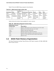
Intel Desktop Board DH61AG Technical Product Specification Table 45 lists the BIOS Setup program menu features. Table 46. tion Performance Clears passwords and displays processor information Displays processor and memory configuration Configures advanced features available through the chipset Configures Memory, Bus and Processor overrides Security Sets passwords and security features Power Configures power management features and power supply controls Boot Selects boot options Exit Saves or discards changes to Setup program options Table 46 lists the function keys available for ...
Intel Desktop Board DH61AG Technical Product Specification Table 45 lists the BIOS Setup program menu features. Table 46. tion Performance Clears passwords and displays processor information Displays processor and memory configuration Configures advanced features available through the chipset Configures Memory, Bus and Processor overrides Security Sets passwords and security features Power Configures power management features and power supply controls Boot Selects boot options Exit Saves or discards changes to Setup program options Table 46 lists the function keys available for ...

Technical Product Specification
Page 83
... write accesses to the hard disk drive until the Master Key or User hard disk drive password is not correctly entered, the system will cause a hard disk to be required to resume system operation. Hard Disk Drive Passwords are set , POST execution will pause with the message: Hard Disk Drive Password Entry Error A manual power cycle will be locked upon each powercycle until the correct password is set in the event that does not support Hard Disk Drive Password Security feature, the drive will...
... write accesses to the hard disk drive until the Master Key or User hard disk drive password is not correctly entered, the system will cause a hard disk to be required to resume system operation. Hard Disk Drive Passwords are set , POST execution will pause with the message: Hard Disk Drive Password Entry Error A manual power cycle will be locked upon each powercycle until the correct password is set in the event that does not support Hard Disk Drive Password Security feature, the drive will...
Technical Product Specification
Page 84
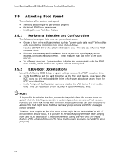
... displays, screen repaints, or mode changes in less than eight seconds that minimizes hard drive startup delays. • Select a CD-ROM drive with the BIOS more quickly. 3.9.2 BIOS Boot Optimizations Use of option ROM boot time. Intel Desktop Board DH61AG Technical Product Specification 3.9 Adjusting Boot Speed These factors affect system boot speed: • Selecting and configuring peripherals properly • Optimized BIOS boot parameters • Enabling the new Fast Boot feature 3.9.1 Peripheral Selection and Configuration The following BIOS Setup program settings reduces the POST...
... displays, screen repaints, or mode changes in less than eight seconds that minimizes hard drive startup delays. • Select a CD-ROM drive with the BIOS more quickly. 3.9.2 BIOS Boot Optimizations Use of option ROM boot time. Intel Desktop Board DH61AG Technical Product Specification 3.9 Adjusting Boot Speed These factors affect system boot speed: • Selecting and configuring peripherals properly • Optimized BIOS boot parameters • Enabling the new Fast Boot feature 3.9.1 Peripheral Selection and Configuration The following BIOS Setup program settings reduces the POST...
Technical Product Specification
Page 89
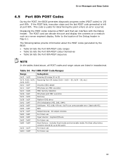
... MRC memory detection PEI phase post MRC execution Recovery Platform DXE driver CPU Initialization (PEI, DXE, SMM) I /O port 80h. For future use For future use 89 Displaying the POST codes requires a POST card that critical since consoles should be up at port 80h. Refer to the location of the Debug header in hexadecimal. Start with the Debug header. Error Messages and Beep Codes 4.5 Port 80h POST Codes During the POST, the BIOS generates diagnostic progress codes (POST codes) to...
... MRC memory detection PEI phase post MRC execution Recovery Platform DXE driver CPU Initialization (PEI, DXE, SMM) I /O port 80h. For future use For future use 89 Displaying the POST codes requires a POST card that critical since consoles should be up at port 80h. Refer to the location of the Debug header in hexadecimal. Start with the Debug header. Error Messages and Beep Codes 4.5 Port 80h POST Codes During the POST, the BIOS generates diagnostic progress codes (POST codes) to...

English Product Guide
Page 3
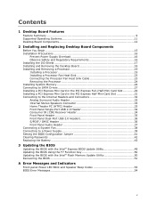
... hardware components 3 Updating the BIOS: instructions on how to update the BIOS A Error Messages and Indicators: information about BIOS error messages and beep codes B Regulatory Compliance: describes the board's adherence to important information. Preface This Product Guide gives information about board layout, component installation, BIOS updates, and regulatory requirements for Intended Applications All Intel Desktop Boards are evaluated as medical, industrial, alarm systems, test equipment, etc. Use Only for Intel® Desktop Board DH61AG. iii
... hardware components 3 Updating the BIOS: instructions on how to update the BIOS A Error Messages and Indicators: information about BIOS error messages and beep codes B Regulatory Compliance: describes the board's adherence to important information. Preface This Product Guide gives information about board layout, component installation, BIOS updates, and regulatory requirements for Intended Applications All Intel Desktop Boards are evaluated as medical, industrial, alarm systems, test equipment, etc. Use Only for Intel® Desktop Board DH61AG. iii
English Product Guide
Page 5
... Panel Header 35 Front Panel Dual-Port USB 2.0 Headers 36 S/PDIF / DMIC Header 36 Front Panel Audio Header 37 Connecting a System Fan 38 Connecting to a Power Supply 39 Setting the BIOS Configuration Jumper 41 Clearing Passwords 42 Replacing the Battery 43 3 Updating the BIOS Updating the BIOS with the Intel® Express BIOS Update Utility 49 Updating the BIOS Using the F7 Function Key 50 Updating the BIOS with the Intel® Flash Memory Update Utility 50 Recovering the BIOS 51 A Error Messages and Indicators Front-panel Power LED Blink and Speaker Beep Codes 53 BIOS Error...
... Panel Header 35 Front Panel Dual-Port USB 2.0 Headers 36 S/PDIF / DMIC Header 36 Front Panel Audio Header 37 Connecting a System Fan 38 Connecting to a Power Supply 39 Setting the BIOS Configuration Jumper 41 Clearing Passwords 42 Replacing the Battery 43 3 Updating the BIOS Updating the BIOS with the Intel® Express BIOS Update Utility 49 Updating the BIOS Using the F7 Function Key 50 Updating the BIOS with the Intel® Flash Memory Update Utility 50 Recovering the BIOS 51 A Error Messages and Indicators Front-panel Power LED Blink and Speaker Beep Codes 53 BIOS Error...

English Product Guide
Page 27
... the power cable to the Desktop Board: 1. Installing and Replacing Desktop Board Components Connecting to SATA Drives Intel Desktop Board DH61AG supports two SATA drives with right-angled connectors and an in "Before You Begin" on page 15. 2. Attach the right-angled 15-pin SATA power connector on the power cable to the SATA drive (Figure 13, B). 4. Observe the precautions in -line power cable that provides: • a right-angled female-gender 15-pin SATA power connector for low-profile board connectivity • a female-gender 1 x 4 Molex-type power connector...
... the power cable to the Desktop Board: 1. Installing and Replacing Desktop Board Components Connecting to SATA Drives Intel Desktop Board DH61AG supports two SATA drives with right-angled connectors and an in "Before You Begin" on page 15. 2. Attach the right-angled 15-pin SATA power connector on the power cable to the SATA drive (Figure 13, B). 4. Observe the precautions in -line power cable that provides: • a right-angled female-gender 15-pin SATA power connector for low-profile board connectivity • a female-gender 1 x 4 Molex-type power connector...

English Product Guide
Page 42
... boot. 7. Intel Desktop Board DH61AG Product Guide The three-pin BIOS jumper block enables board configuration to be done in the event of a failed BIOS update. Replace the cover, plug in the computer and the configuration jumper block is set to normal mode. 1. Select Yes and press the Enter key. Press the F10 key to clear passwords. The BIOS recovers data in the BIOS Setup program. Press the Enter key and Setup displays a pop-up screen requesting that the board is installed in the computer, turn...
... boot. 7. Intel Desktop Board DH61AG Product Guide The three-pin BIOS jumper block enables board configuration to be done in the event of a failed BIOS update. Replace the cover, plug in the computer and the configuration jumper block is set to normal mode. 1. Select Yes and press the Enter key. Press the F10 key to clear passwords. The BIOS recovers data in the BIOS Setup program. Press the Enter key and Setup displays a pop-up screen requesting that the board is installed in the computer, turn...


