
Product Guide
Page 3
... features 2 Installing and Replacing Desktop Board Components: instructions on how to install the Desktop Board and other hardware components 3 Updating the BIOS: instructions on how to update the BIOS A Error Messages and Indicators: information about BIOS error messages and beep codes B Regulatory Compliance: describes the board's adherence to safety standards and EMC regulations and its product certifications Conventions The following conventions are evaluated as Information Technology Equipment (I.T.E.) for use in homes...
... features 2 Installing and Replacing Desktop Board Components: instructions on how to install the Desktop Board and other hardware components 3 Updating the BIOS: instructions on how to update the BIOS A Error Messages and Indicators: information about BIOS error messages and beep codes B Regulatory Compliance: describes the board's adherence to safety standards and EMC regulations and its product certifications Conventions The following conventions are evaluated as Information Technology Equipment (I.T.E.) for use in homes...
Product Guide
Page 5
... Chipset 14 Main Memory...15 Graphics Subsystem 15 Integrated Graphics 15 Analog Display (VGA 15 High-Definition Multimedia Interface* (HDMI 16 Digital Visual Interface (DVI-D 16 PCI Express* x16 Graphics 16 Audio Subsystem 17 LAN Subsystem 17 USB 2.0 Support 18 Serial ATA Support 18 Expandability...19 Legacy I/O ...19 BIOS ...19 Serial ATA Auto Configuration 19 PCI*/PCI Express Auto Configuration 19 Security Passwords 20 Hardware Management 20 Hardware Monitoring and Fan Speed Control 20 Fan Monitoring 20 Chassis Intrusion 21 Power Management 21 Software Support 21 ACPI...
... Chipset 14 Main Memory...15 Graphics Subsystem 15 Integrated Graphics 15 Analog Display (VGA 15 High-Definition Multimedia Interface* (HDMI 16 Digital Visual Interface (DVI-D 16 PCI Express* x16 Graphics 16 Audio Subsystem 17 LAN Subsystem 17 USB 2.0 Support 18 Serial ATA Support 18 Expandability...19 Legacy I/O ...19 BIOS ...19 Serial ATA Auto Configuration 19 PCI*/PCI Express Auto Configuration 19 Security Passwords 20 Hardware Management 20 Hardware Monitoring and Fan Speed Control 20 Fan Monitoring 20 Chassis Intrusion 21 Power Management 21 Software Support 21 ACPI...

Product Guide
Page 6
...a PCI Express x16 Graphics Card 41 Removing a PCI Express x16 Graphics Card 42 Connecting Serial ATA (SATA) Cables 44 Installing an Intel® Z-U130 USB Solid-State Drive (or Compatible Device 45 Connecting to the Internal Headers 46 Front Panel Audio Header 47 Internal Mono Speaker Header 47 S/PDIF Header 48 Parallel Port Header 48 Chassis Intrusion Header 49 Intel® RPAT Header 49 Alternate Front Panel Power LED Header 49 Front Panel Header 50 Front Panel USB 2.0 Headers 50 Serial Header 51 Connecting to the Audio System 52 Connecting Chassis Fan and Power Supply Cables...
...a PCI Express x16 Graphics Card 41 Removing a PCI Express x16 Graphics Card 42 Connecting Serial ATA (SATA) Cables 44 Installing an Intel® Z-U130 USB Solid-State Drive (or Compatible Device 45 Connecting to the Internal Headers 46 Front Panel Audio Header 47 Internal Mono Speaker Header 47 S/PDIF Header 48 Parallel Port Header 48 Chassis Intrusion Header 49 Intel® RPAT Header 49 Alternate Front Panel Power LED Header 49 Front Panel Header 50 Front Panel USB 2.0 Headers 50 Serial Header 51 Connecting to the Audio System 52 Connecting Chassis Fan and Power Supply Cables...
Product Guide
Page 7
... Considerations 71 Lead-free 2LI/Pb-free 2LI Board 74 Restriction of the Chassis Fan Headers 53 26. LAN Connector LEDs 18 3. Intel Desktop Board DH55HC Mounting Screw Hole Locations 30 6. Lift the Load Plate 32 8. Secure the Load Plate in Place 35 13. Use DDR3 DIMMs 39 18. Installing a DIMM 40 19. Removing a PCI Express x16 Graphics Card 43 21. Connecting a Serial ATA Cable 44 22. Installing an Intel Z-U130 USB Solid-State Drive (or Compatible Device 45 23. Location of Hazardous...
... Considerations 71 Lead-free 2LI/Pb-free 2LI Board 74 Restriction of the Chassis Fan Headers 53 26. LAN Connector LEDs 18 3. Intel Desktop Board DH55HC Mounting Screw Hole Locations 30 6. Lift the Load Plate 32 8. Secure the Load Plate in Place 35 13. Use DDR3 DIMMs 39 18. Installing a DIMM 40 19. Removing a PCI Express x16 Graphics Card 43 21. Connecting a Serial ATA Cable 44 22. Installing an Intel Z-U130 USB Solid-State Drive (or Compatible Device 45 23. Location of Hazardous...
Product Guide
Page 8
Front-panel Power LED Blink Codes 68 19. Intel Desktop Board DH55HC Components 13 3. LAN Connector LEDs 18 4. Internal Mono Speaker Header 47 7. USB 2.0 Header Signal Names 50 14. Front Panel USB Header (with Intel Z-U130 USB Solid-State Drive (or Compatible Device) Support) Signal Names 51 15. Front Panel Audio Signal Names for the BIOS Setup Program Modes 56 17. Chassis Intrusion Header Signal Names 49 10. Jumper Settings for Intel HD Audio 47 5. Front Panel Header Signal Names 50 13. BIOS Error Messages 68 20. EMC Regulations 78 24...
Front-panel Power LED Blink Codes 68 19. Intel Desktop Board DH55HC Components 13 3. LAN Connector LEDs 18 4. Internal Mono Speaker Header 47 7. USB 2.0 Header Signal Names 50 14. Front Panel USB Header (with Intel Z-U130 USB Solid-State Drive (or Compatible Device) Support) Signal Names 51 15. Front Panel Audio Signal Names for the BIOS Setup Program Modes 56 17. Chassis Intrusion Header Signal Names 49 10. Jumper Settings for Intel HD Audio 47 5. Front Panel Header Signal Names 50 13. BIOS Error Messages 68 20. EMC Regulations 78 24...
Product Guide
Page 10
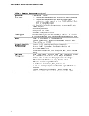
...8226; Three fan headers using PWM control • 4-pin headers for processor, front, and rear fans • 4-wire and 3-wire (linear) fan speed control support for front and rear fans • Support for Platform Environmental Control Interface (PECI) 10 Intel Desktop Board DH55HC Product Guide Table 1. one header supports an Intel Z-U130 USB Solid-State Drive (or compatible device) • Six Serial ATA (SATA) 3.0 Gb/s ports, two ports compatible with eSATA adapters • One serial port header • One parallel port header • One PS/2 back panel connector Intel® 82578DC...
...8226; Three fan headers using PWM control • 4-pin headers for processor, front, and rear fans • 4-wire and 3-wire (linear) fan speed control support for front and rear fans • Support for Platform Environmental Control Interface (PECI) 10 Intel Desktop Board DH55HC Product Guide Table 1. one header supports an Intel Z-U130 USB Solid-State Drive (or compatible device) • Six Serial ATA (SATA) 3.0 Gb/s ports, two ports compatible with eSATA adapters • One serial port header • One parallel port header • One PS/2 back panel connector Intel® 82578DC...
Product Guide
Page 13
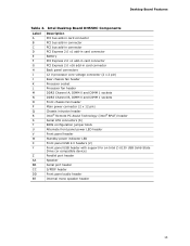
... Channel B, DIMM 0 and DIMM 1 sockets Front chassis fan header Main power connector (2 x 12 pin) Chassis intrusion header Intel® Remote PC Assist Technology (Intel® RPAT) header Serial ATA connectors (6) BIOS configuration jumper block Alternate front panel power LED header Front panel header Standby power indicator LED Front panel USB 2.0 headers (2) Front panel USB header with support for an Intel Z-U130 USB Solid-State Drive (or compatible device) Parallel port header Speaker Serial port header S/PDIF header Front panel audio header Internal mono speaker header 13 Desktop Board...
... Channel B, DIMM 0 and DIMM 1 sockets Front chassis fan header Main power connector (2 x 12 pin) Chassis intrusion header Intel® Remote PC Assist Technology (Intel® RPAT) header Serial ATA connectors (6) BIOS configuration jumper block Alternate front panel power LED header Front panel header Standby power indicator LED Front panel USB 2.0 headers (2) Front panel USB header with support for an Intel Z-U130 USB Solid-State Drive (or compatible device) Parallel port header Speaker Serial port header S/PDIF header Front panel audio header Internal mono speaker header 13 Desktop Board...
Product Guide
Page 17
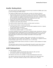
... LEDs are capable of retasking according to an internal, lowpower speaker for front panel audio connectors) • S/PDIF audio header (1 x 4 pin header) • Internal mono speaker header (1 x 2 pin header) Front panel headphone output is capable of driving a target speaker load of 8 Ω at 1 W (rms) or 4 Ω at http://downloadcenter.intel.com/. The subsystem is supported by a separate audio channel pair, allowing multi-streaming audio configurations such as through the HDMI interface. The onboard internal mono speaker header allows connection to the user...
... LEDs are capable of retasking according to an internal, lowpower speaker for front panel audio connectors) • S/PDIF audio header (1 x 4 pin header) • Internal mono speaker header (1 x 2 pin header) Front panel headphone output is capable of driving a target speaker load of 8 Ω at 1 W (rms) or 4 Ω at http://downloadcenter.intel.com/. The subsystem is supported by a separate audio channel pair, allowing multi-streaming audio configurations such as through the HDMI interface. The onboard internal mono speaker header allows connection to the user...
Product Guide
Page 19
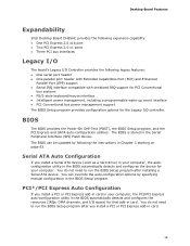
Desktop Board Features Expandability Intel Desktop Board DH55HC provides the following expansion capability: • One PCI Express 2.0 x16 port • Two PCI Express 2.0 x1 ports • Three PCI bus interfaces Legacy I/O The board's Legacy I /O controller. The BIOS is stored in card. 19 BIOS The BIOS provides the Power-On Self-Test (POST), the BIOS Setup program, and the PCI Express and SATA auto-configuration utilities. Serial ATA Auto Configuration If you install a Serial ATA device (such as a hard drive) in your computer, the autoconfiguration utility in the BIOS automatically ...
Desktop Board Features Expandability Intel Desktop Board DH55HC provides the following expansion capability: • One PCI Express 2.0 x16 port • Two PCI Express 2.0 x1 ports • Three PCI bus interfaces Legacy I/O The board's Legacy I /O controller. The BIOS is stored in card. 19 BIOS The BIOS provides the Power-On Self-Test (POST), the BIOS Setup program, and the PCI Express and SATA auto-configuration utilities. Serial ATA Auto Configuration If you install a Serial ATA device (such as a hard drive) in your computer, the autoconfiguration utility in the BIOS automatically ...
Product Guide
Page 21
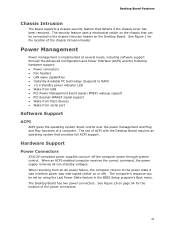
... ACPI-enabled computer receives the correct command, the power supply removes all non-standby voltages. Desktop Board Features Chassis Intrusion The board supports a chassis security feature that detects if the chassis cover has been removed. See Figure 26 on or off the computer power through the Advanced Configuration and Power Interface (ACPI) and the following hardware support: • Power connectors • Fan headers • LAN wake capabilities • Instantly Available PC technology (Suspend to RAM) • +5 V standby power...
... ACPI-enabled computer receives the correct command, the power supply removes all non-standby voltages. Desktop Board Features Chassis Intrusion The board supports a chassis security feature that detects if the chassis cover has been removed. See Figure 26 on or off the computer power through the Advanced Configuration and Power Interface (ACPI) and the following hardware support: • Power connectors • Fan headers • LAN wake capabilities • Instantly Available PC technology (Suspend to RAM) • +5 V standby power...
Product Guide
Page 27
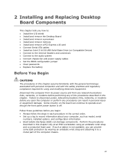
... off. 2 Installing and Replacing Desktop Board Components This chapter tells you how to: • Install the I/O shield • Install and remove the Desktop Board • Install and remove a processor • Install and remove memory • Install and remove a PCI Express x16 card • Connect Serial ATA cables • Install an Intel Z-U130 USB Solid-State Drive (or Compatible Device) • Connect to the internal headers and connectors • Connect to a metal part of the procedures described in this chapter only at an ESD workstation using and...
... off. 2 Installing and Replacing Desktop Board Components This chapter tells you how to: • Install the I/O shield • Install and remove the Desktop Board • Install and remove a processor • Install and remove memory • Install and remove a PCI Express x16 card • Connect Serial ATA cables • Install an Intel Z-U130 USB Solid-State Drive (or Compatible Device) • Connect to the internal headers and connectors • Connect to a metal part of the procedures described in this chapter only at an ESD workstation using and...
Product Guide
Page 56
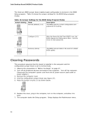
... power source (wall outlet or power adapter). 3. Use this menu to normal mode. 1. The computer starts the Setup program. Table 16. Turn off the computer. Intel Desktop Board DH55HC Product Guide The three-pin BIOS jumper block enables board configuration to the computer. Remove the computer cover. 4. Setup displays the Maintenance menu. 56 Place the jumper on page 27. 2. Replace the cover, plug in the event of a failed BIOS update. Find the configuration jumper block (see Figure 27). 5. Recovery (None) The BIOS...
... power source (wall outlet or power adapter). 3. Use this menu to normal mode. 1. The computer starts the Setup program. Table 16. Turn off the computer. Intel Desktop Board DH55HC Product Guide The three-pin BIOS jumper block enables board configuration to the computer. Remove the computer cover. 4. Setup displays the Maintenance menu. 56 Place the jumper on page 27. 2. Replace the cover, plug in the event of a failed BIOS update. Find the configuration jumper block (see Figure 27). 5. Recovery (None) The BIOS...
Product Guide
Page 63
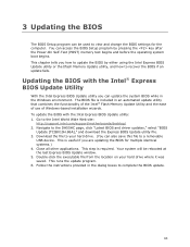
...; Express BIOS Update Utility With the Intel Express BIOS Update utility you how to your hard drive where it was saved. Follow the instructions provided in an automated update utility that combines the functionality of the Intel® Flash Memory Update Utility and the ease of use of Windows-based installation wizards. Navigate to the Intel World Wide Web site: http://support.intel.com/support/motherboards/desktop/ 2. Download the file to update the BIOS by pressing the key after the Power-On Self-Test (POST) memory...
...; Express BIOS Update Utility With the Intel Express BIOS Update utility you how to your hard drive where it was saved. Follow the instructions provided in an automated update utility that combines the functionality of the Intel® Flash Memory Update Utility and the ease of use of Windows-based installation wizards. Navigate to the Intel World Wide Web site: http://support.intel.com/support/motherboards/desktop/ 2. Download the file to update the BIOS by pressing the key after the Power-On Self-Test (POST) memory...
Intel Desktop Board DH55HC Technical Product Specification
Page 7
... Standby Power LED 33 8. Front Panel USB Header (with Intel Z-U130 USB Solid-State Drive, or Compatible Device, Support 48 14. System Memory Map 37 9. Chassis Intrusion Header 43 20. Connection Diagram for Front Panel Header 46 12. Intel Remote PC Assist Technology Header 44 23. LAN Connector LED Locations 24 6. Detailed System Memory Address Map 36 9. Supported Memory Configurations 15 4. Front Panel USB Header 42 17. SATA Connectors 43 19. Processor (4-Pin) Fan Header 43 21. Processor Core Power Connector 44 24. Location of the Jumper Block 49 15. Board...
... Standby Power LED 33 8. Front Panel USB Header (with Intel Z-U130 USB Solid-State Drive, or Compatible Device, Support 48 14. System Memory Map 37 9. Chassis Intrusion Header 43 20. Connection Diagram for Front Panel Header 46 12. Intel Remote PC Assist Technology Header 44 23. LAN Connector LED Locations 24 6. Detailed System Memory Address Map 36 9. Supported Memory Configurations 15 4. Front Panel USB Header 42 17. SATA Connectors 43 19. Processor (4-Pin) Fan Header 43 21. Processor Core Power Connector 44 24. Location of the Jumper Block 49 15. Board...
Intel Desktop Board DH55HC Technical Product Specification
Page 8
Intel Desktop Board DH55HC Technical Product Specification 26. BIOS Setup Configuration Jumper Settings 50 29. Recommended Power Supply Current Values 52 30. Thermal Considerations for BIOS Recovery 63 37. Acceptable Drives/Media Types for Components 55 32. Front-panel Power LED Blink Codes 68 41. Auxiliary Front Panel Power LED Header 47 28. Port 80h POST Code Ranges 69 43. Lead-Free Board Markings 80 47. Fan Header Current Capability 53 31. BIOS Setup Program Menu Bar 60 35. BIOS Error Messages 68 42. States for Components...
Intel Desktop Board DH55HC Technical Product Specification 26. BIOS Setup Configuration Jumper Settings 50 29. Recommended Power Supply Current Values 52 30. Thermal Considerations for BIOS Recovery 63 37. Acceptable Drives/Media Types for Components 55 32. Front-panel Power LED Blink Codes 68 41. Auxiliary Front Panel Power LED Header 47 28. Port 80h POST Code Ranges 69 43. Lead-Free Board Markings 80 47. Fan Header Current Capability 53 31. BIOS Setup Program Menu Bar 60 35. BIOS Error Messages 68 42. States for Components...
Intel Desktop Board DH55HC Technical Product Specification
Page 48
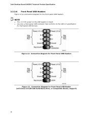
Figure 12. Connection Diagram for Front Panel USB Headers Figure 13. Connection Diagram for Front Panel USB Header (with Intel Z-U130 USB Solid-State Drive, or Compatible Device, Support) 48 Intel Desktop Board DH55HC Technical Product Specification 2.2.2.6 Front Panel USB Headers Figure 12 is fused. • Use only a front panel USB connector that conforms to the USB 2.0 specification for high-speed USB devices. NOTE • The +5 V DC power on the USB headers is a connection diagram for the front panel USB headers.
Figure 12. Connection Diagram for Front Panel USB Headers Figure 13. Connection Diagram for Front Panel USB Header (with Intel Z-U130 USB Solid-State Drive, or Compatible Device, Support) 48 Intel Desktop Board DH55HC Technical Product Specification 2.2.2.6 Front Panel USB Headers Figure 12 is fused. • Use only a front panel USB connector that conforms to the USB 2.0 specification for high-speed USB devices. NOTE • The +5 V DC power on the USB headers is a connection diagram for the front panel USB headers.
Intel Desktop Board DH55HC Technical Product Specification
Page 68
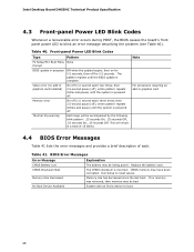
..., then off . Intel Desktop Board DH55HC Technical Product Specification 4.3 Front-panel Power LED Blink Codes Whenever a recoverable error occurs during POST, the BIOS causes the board's front panel power LED to boot. 68 CMOS memory may be bad. No Boot Device Available System did not find a device to blink an error message describing the problem (see Table 40). Video error (no memory was removed, then memory may have been corrupted. Run Setup to reset values. Table 41. Replace the battery soon. The pattern...
..., then off . Intel Desktop Board DH55HC Technical Product Specification 4.3 Front-panel Power LED Blink Codes Whenever a recoverable error occurs during POST, the BIOS causes the board's front panel power LED to boot. 68 CMOS memory may be bad. No Boot Device Available System did not find a device to blink an error message describing the problem (see Table 40). Video error (no memory was removed, then memory may have been corrupted. Run Setup to reset values. Table 41. Replace the battery soon. The pattern...
Intel Desktop Board DH55HC Technical Product Specification
Page 69
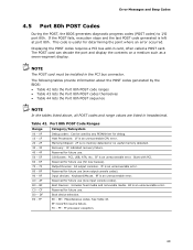
... CPU error. 20 - 2F Memory/Chipset: 2F is an unrecoverable error. BF Boot Devices: Includes fixed media and removable media. Error Messages and Beep Codes 4.5 Port 80h POST Codes During the POST, the BIOS generates diagnostic progress codes (POST codes) to I /O Busses: PCI, USB, ATA, etc. 5F is no memory detected or no useful memory detected. 30 - 3F Recovery: 3F indicated recovery failure. 40 - 4F Reserved for determining the point where an error occurred. This code is useful for future use...
... CPU error. 20 - 2F Memory/Chipset: 2F is an unrecoverable error. BF Boot Devices: Includes fixed media and removable media. Error Messages and Beep Codes 4.5 Port 80h POST Codes During the POST, the BIOS generates diagnostic progress codes (POST codes) to I /O Busses: PCI, USB, ATA, etc. 5F is no memory detected or no useful memory detected. 30 - 3F Recovery: 3F indicated recovery failure. 40 - 4F Reserved for determining the point where an error occurred. This code is useful for future use...
Intel Desktop Board DH55HC Technical Product Specification
Page 73
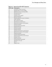
Error Messages and Beep Codes Table 44. Typical Port 80h POST Sequence POST Code Description 21 Initializing a chipset component 22 Reading SPD from memory DIMMs 23 Detecting presence of memory DIMMs 25 Configuring memory 28 Testing memory 34 Loading recovery capsule E4 Entered DXE phase 12 Starting application processor initialization 13 SMM initialization 50 Enumerating PCI busses 51 Allocating resourced to PCI bus 92 Detecting the presence of the keyboard 90 Resetting keyboard 94 Clearing keyboard input...
Error Messages and Beep Codes Table 44. Typical Port 80h POST Sequence POST Code Description 21 Initializing a chipset component 22 Reading SPD from memory DIMMs 23 Detecting presence of memory DIMMs 25 Configuring memory 28 Testing memory 34 Loading recovery capsule E4 Entered DXE phase 12 Starting application processor initialization 13 SMM initialization 50 Enumerating PCI busses 51 Allocating resourced to PCI bus 92 Detecting the presence of the keyboard 90 Resetting keyboard 94 Clearing keyboard input...
Intel Desktop Board DH55HC Specification Update
Page 7
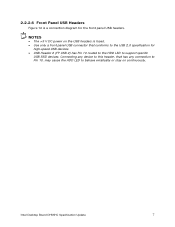
NOTES • The +5 V DC power on continuously. 2.2.2.6 Front Panel USB Headers Figure 12 is fused. • Use only a front panel USB connector that has any device to this header, that conforms to support specific USB SSD devices. Intel Desktop Board DH55HC Specification Update 7 Connecting any connection to Pin 10, may cause the HDD LED to behave erratically or stay on the USB headers is a connection diagram for high-speed USB devices. • USB Header 2 (FP USB 2) has Pin 10 routed to the HDD LED to the USB 2.0 specification for the front panel USB headers.
NOTES • The +5 V DC power on continuously. 2.2.2.6 Front Panel USB Headers Figure 12 is fused. • Use only a front panel USB connector that has any device to this header, that conforms to support specific USB SSD devices. Intel Desktop Board DH55HC Specification Update 7 Connecting any connection to Pin 10, may cause the HDD LED to behave erratically or stay on the USB headers is a connection diagram for high-speed USB devices. • USB Header 2 (FP USB 2) has Pin 10 routed to the HDD LED to the USB 2.0 specification for the front panel USB headers.


