Product Guide
Page 6
Intel Desktop Board DG45FC Product Guide Installing the I/O Shield 29 Installing and Removing the Desktop Board 30 Installing and Removing a Processor 31 Installing a Processor 31 Installing a Processor Fan Heat Sink 34 Connecting the Processor Fan Heat Sink Cable 35 Removing the... Audio Header 42 Chassis Intrusion Header 42 Consumer IR (CIR) Headers 42 USB 2.0 Headers 43 Serial Port Header 44 Alternate Front Panel Power LED Header 44 Front Panel Header 44 Connecting to the Audio System 45 Connecting Chassis Fan and Power Supply Cables 46 Chassis Fan Cables 46 Power Supply Cables...
Intel Desktop Board DG45FC Product Guide Installing the I/O Shield 29 Installing and Removing the Desktop Board 30 Installing and Removing a Processor 31 Installing a Processor 31 Installing a Processor Fan Heat Sink 34 Connecting the Processor Fan Heat Sink Cable 35 Removing the... Audio Header 42 Chassis Intrusion Header 42 Consumer IR (CIR) Headers 42 USB 2.0 Headers 43 Serial Port Header 44 Alternate Front Panel Power LED Header 44 Front Panel Header 44 Connecting to the Audio System 45 Connecting Chassis Fan and Power Supply Cables 46 Chassis Fan Cables 46 Power Supply Cables...
Product Guide
Page 7
... Fan Heat Sink Cable 35 13. Internal Headers and Connectors 41 18. Connecting Power Supply Cables 47 21. Desktop Board DG45FC China RoHS Material Self Declaration Table 75 Tables 1. LAN Status LEDs 18 3. Lift the Load Plate 32 ... Plate 34 12. Installing a DIMM 38 16. Feature Summary 9 2. Desktop Board DG45FC Mounting Screw Hole Locations 30 6. Desktop Board DG45FC Components 12 3. Audio Jack Retasking Support 16 4. Desktop Board DG45FC Components 11 2. Back Panel Audio Connectors 45 19. Dual Channel Memory Configuration Example 36 14. Connecting ...
... Fan Heat Sink Cable 35 13. Internal Headers and Connectors 41 18. Connecting Power Supply Cables 47 21. Desktop Board DG45FC China RoHS Material Self Declaration Table 75 Tables 1. LAN Status LEDs 18 3. Lift the Load Plate 32 ... Plate 34 12. Installing a DIMM 38 16. Feature Summary 9 2. Desktop Board DG45FC Mounting Screw Hole Locations 30 6. Desktop Board DG45FC Components 12 3. Audio Jack Retasking Support 16 4. Desktop Board DG45FC Components 11 2. Back Panel Audio Connectors 45 19. Dual Channel Memory Configuration Example 36 14. Connecting ...
Product Guide
Page 8
Intel Desktop Board DG45FC Product Guide 5. Chassis Intrusion Header 42 7. Back Panel CIR Header Emitter (Output) Header Signal Names 43 9. China RoHS Environmentally Friendly Use Period Mark 74 19. USB 2.0 Header Signal Names 43 10. Jumper Settings for Intel High Definition Audio 42 6. BIOS Error Messages 65 16. Product Certification Markings 78 viii Front Panel Audio Header Signal...
Intel Desktop Board DG45FC Product Guide 5. Chassis Intrusion Header 42 7. Back Panel CIR Header Emitter (Output) Header Signal Names 43 9. China RoHS Environmentally Friendly Use Period Mark 74 19. USB 2.0 Header Signal Names 43 10. Jumper Settings for Intel High Definition Audio 42 6. BIOS Error Messages 65 16. Product Certification Markings 78 viii Front Panel Audio Header Signal...
Product Guide
Page 9
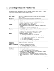
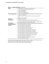
... panel ― Four ports routed to two onboard headers • Five Serial ATA (SATA) channels (3.0 Gb/s) via ICH10R including one external SATA (eSATA) channel • SATA RAID support via Intel® Matrix Storage Technology (Intel® MST) including support for up to 4 GB of system memory Intel® G45 Express Chipset consisting of Intel® Desktop Board DG45FC...
... panel ― Four ports routed to two onboard headers • Five Serial ATA (SATA) channels (3.0 Gb/s) via ICH10R including one external SATA (eSATA) channel • SATA RAID support via Intel® Matrix Storage Technology (Intel® MST) including support for up to 4 GB of system memory Intel® G45 Express Chipset consisting of Intel® Desktop Board DG45FC...
Product Guide
Page 10
... panel, and consumer IR • ENERGY STAR* capable Hardware Management Hardware monitor with: • Three fan sensing inputs used to monitor fan activity • Intel® Quiet System Technology (Intel&#...Media Center Edition 2005 • Microsoft Windows XP Professional • Microsoft Windows XP Professional x64 Edition • Microsoft Windows XP Home For more information about Desktop Board DG45FC, including the Technical Product Specification (TPS), BIOS updates, and device drivers, go to http://support.intel.com/support/motherboards/desktop/. 10 Intel Desktop Board DG45FC...
... panel, and consumer IR • ENERGY STAR* capable Hardware Management Hardware monitor with: • Three fan sensing inputs used to monitor fan activity • Intel® Quiet System Technology (Intel&#...Media Center Edition 2005 • Microsoft Windows XP Professional • Microsoft Windows XP Professional x64 Edition • Microsoft Windows XP Home For more information about Desktop Board DG45FC, including the Technical Product Specification (TPS), BIOS updates, and device drivers, go to http://support.intel.com/support/motherboards/desktop/. 10 Intel Desktop Board DG45FC...
Product Guide
Page 15
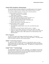
...Intel Viiv technology brand, a system must meet certain hardware and software requirements. also supports 1920 x 1080 resolution for full High Definition video playback quality DVI-I Support The DVI-I and HDMI support via the DVI-I and HDMI back panel...including: ⎯ DVI specification 1.0 compliance ⎯ Dual independent display support via the integrated Intel Graphics Media Accelerator X4500HD (GMA X4500HD) graphics controller. Desktop Board Features Intel G45 Graphics Subsystem The Intel G45 Express Chipset provides DVI-I port supports both digital and analog DVI displays.
...Intel Viiv technology brand, a system must meet certain hardware and software requirements. also supports 1920 x 1080 resolution for full High Definition video playback quality DVI-I Support The DVI-I and HDMI support via the DVI-I and HDMI back panel...including: ⎯ DVI specification 1.0 compliance ⎯ Dual independent display support via the integrated Intel Graphics Media Accelerator X4500HD (GMA X4500HD) graphics controller. Desktop Board Features Intel G45 Graphics Subsystem The Intel G45 Express Chipset provides DVI-I port supports both digital and analog DVI displays.
Product Guide
Page 16
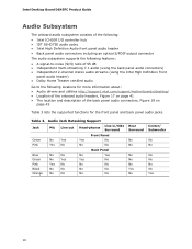
Intel Desktop Board DG45FC Product Guide Audio Subsystem The onboard audio subsystem consists of the following: • Intel ICH10R I/O controller hub • IDT 92HD73E audio codec • Intel High Definition Audio front panel audio header • Back panel audio connectors including an optical S/PDIF output connector The audio ...: • Audio drivers and utilities http://support.intel.com/support/motherboards/desktop/ • Location of the onboard audio headers, Figure 17 on page 41 • The location and description of the back panel audio connectors, Figure 18 on page 45 Table...
Intel Desktop Board DG45FC Product Guide Audio Subsystem The onboard audio subsystem consists of the following: • Intel ICH10R I/O controller hub • IDT 92HD73E audio codec • Intel High Definition Audio front panel audio header • Back panel audio connectors including an optical S/PDIF output connector The audio ...: • Audio drivers and utilities http://support.intel.com/support/motherboards/desktop/ • Location of the onboard audio headers, Figure 17 on page 41 • The location and description of the back panel audio connectors, Figure 18 on page 45 Table...
Product Guide
Page 17
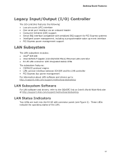
Desktop Board Features Legacy Input/Output (I/O) Controller The I/O controller features the following... event interface • PCI Express power management support LAN Subsystem The LAN subsystem includes: • Intel® ICH10R • Intel 82567LF Gigabit (10/100/1000 Mb/s) Ethernet LAN controller • RJ-45 LAN connector with integrated...go to http://support.intel.com/support/motherboards/desktop LAN Subsystem Software For LAN software and drivers, refer to the DG45FC link on Intel's World Wide Web site at http://support.intel.com/support/motherboards/desktop. LAN Status Indicators...
Desktop Board Features Legacy Input/Output (I/O) Controller The I/O controller features the following... event interface • PCI Express power management support LAN Subsystem The LAN subsystem includes: • Intel® ICH10R • Intel 82567LF Gigabit (10/100/1000 Mb/s) Ethernet LAN controller • RJ-45 LAN connector with integrated...go to http://support.intel.com/support/motherboards/desktop LAN Subsystem Software For LAN software and drivers, refer to the DG45FC link on Intel's World Wide Web site at http://support.intel.com/support/motherboards/desktop. LAN Status Indicators...
Product Guide
Page 18
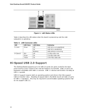
... is occurring 10 Mb/s data rate 100 Mb/s data rate 1000 Mb/s data rate Hi-Speed USB 2.0 Support The Desktop Board supports up to 10 USB 2.0 ports (six ports routed to the back panel and four ports routed to two internal headers) via ICH10R. LAN Connector LEDs LED A (Link) B (Speed) LED Color Green... 1.1 operation. USB 1.1 devices will function normally at USB 1.1 speeds. Table 4. USB 2.0 support requires both an operating system and drivers that do not support USB 2.0. 18 Intel Desktop Board DG45FC Product Guide Figure 2.
... is occurring 10 Mb/s data rate 100 Mb/s data rate 1000 Mb/s data rate Hi-Speed USB 2.0 Support The Desktop Board supports up to 10 USB 2.0 ports (six ports routed to the back panel and four ports routed to two internal headers) via ICH10R. LAN Connector LEDs LED A (Link) B (Speed) LED Color Green... 1.1 operation. USB 1.1 devices will function normally at USB 1.1 speeds. Table 4. USB 2.0 support requires both an operating system and drivers that do not support USB 2.0. 18 Intel Desktop Board DG45FC Product Guide Figure 2.
Product Guide
Page 23
The Desktop Board supports the PCI Bus Power Management Interface Specification. LAN wakeup capabilities enable remote wake-up device or event, the computer quickly returns to its last known awake state. If the computer has a dual-colored power LED on the front panel, the sleep state is ...standby current. LAN Wake Capabilities CAUTION For LAN wake capabilities, the 5 V standby line for the power supply must be used with this Desktop Board must be off when the computer is indicated by a wake-up of the computer through a network. If the standby current necessary to support...
The Desktop Board supports the PCI Bus Power Management Interface Specification. LAN wakeup capabilities enable remote wake-up device or event, the computer quickly returns to its last known awake state. If the computer has a dual-colored power LED on the front panel, the sleep state is ...standby current. LAN Wake Capabilities CAUTION For LAN wake capabilities, the 5 V standby line for the power supply must be used with this Desktop Board must be off when the computer is indicated by a wake-up of the computer through a network. If the standby current necessary to support...
Product Guide
Page 27
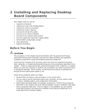
... of the computer chassis. 27 If such a station is off. 2 Installing and Replacing Desktop Board Components This chapter tells you how to: • Install the I/O shield • Install and remove the Desktop Board • Install and remove a processor • Install and remove memory • Connect ..., or modems before you can damage components. Follow these guidelines before performing any procedures can continue to operate even though the front panel power button is not available, you begin: • Always follow the steps in each procedure in the correct order. •...
... of the computer chassis. 27 If such a station is off. 2 Installing and Replacing Desktop Board Components This chapter tells you how to: • Install the I/O shield • Install and remove the Desktop Board • Install and remove a processor • Install and remove memory • Connect ..., or modems before you can damage components. Follow these guidelines before performing any procedures can continue to operate even though the front panel power button is not available, you begin: • Always follow the steps in each procedure in the correct order. •...
Product Guide
Page 41
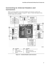
Installing and Replacing Desktop Board Components Connecting to Internal Headers and Connectors Before connecting cables to the internal headers and connectors, observe the precautions in "Before You Begin" on page 27. Internal Headers and Connectors 41 Figure 17 shows the location of the internal headers and connectors. Item Description Item Description A Audio E Serial B Chassis intrusion F Front panel CIR receiver C Back panel CIR emitter G Alternate front panel power LED D USB 2.0 H Front panel Figure 17.
Installing and Replacing Desktop Board Components Connecting to Internal Headers and Connectors Before connecting cables to the internal headers and connectors, observe the precautions in "Before You Begin" on page 27. Internal Headers and Connectors 41 Figure 17 shows the location of the internal headers and connectors. Item Description Item Description A Audio E Serial B Chassis intrusion F Front panel CIR receiver C Back panel CIR emitter G Alternate front panel power LED D USB 2.0 H Front panel Figure 17.

Product Guide
Page 42
... 6 SENSE1_RETURN 7 SENSE_SEND 9 PORT 2L 8 KEY (no pin) 10 SENSE2_RETURN To install the cable that connects your front panel audio solution to the computer. The emitter header consists of other user remotes. Intel Desktop Board DG45FC Product Guide Front Panel HD Audio Header Figure 17, A shows the location of a filtered translated infrared input compliant with Microsoft CIR...
... 6 SENSE1_RETURN 7 SENSE_SEND 9 PORT 2L 8 KEY (no pin) 10 SENSE2_RETURN To install the cable that connects your front panel audio solution to the computer. The emitter header consists of other user remotes. Intel Desktop Board DG45FC Product Guide Front Panel HD Audio Header Figure 17, A shows the location of a filtered translated infrared input compliant with Microsoft CIR...

Product Guide
Page 43
... at boot to enter the system BIOS, and go to Advanced > Peripheral Configuration > Enhanced Consumer IR, and set this option to the cable. Table 7. Back Panel CIR Emitter (Output) Header Signal Names Pin Signal Name 1 Emitter Out 1 3 Ground 5 Jack Detect 1 Pin Signal Name 2 Emitter Out 2 4 Key (no ... systems that meets the requirements for the location of the two USB 2.0 headers. Each USB header can function. Installing and Replacing Desktop Board Components NOTE The Consumer IR option must be enabled in the system BIOS before it can be assigned as needed.
... at boot to enter the system BIOS, and go to Advanced > Peripheral Configuration > Enhanced Consumer IR, and set this option to the cable. Table 7. Back Panel CIR Emitter (Output) Header Signal Names Pin Signal Name 1 Emitter Out 1 3 Ground 5 Jack Detect 1 Pin Signal Name 2 Emitter Out 2 4 Key (no ... systems that meets the requirements for the location of the two USB 2.0 headers. Each USB header can function. Installing and Replacing Desktop Board Components NOTE The Consumer IR option must be enabled in the system BIOS before it can be assigned as needed.

Product Guide
Page 44
... Hard Drive Activity LED Power LED 1 Hard disk LED pull-up to this header duplicate the signals on pins 2 and 4 of the alternate front panel power LED header. Table 11. Pins 1 and 3 of this header. Intel Desktop Board DG45FC Product Guide Serial Port Header See Figure 17, E for the location of the multi-colored front...
... Hard Drive Activity LED Power LED 1 Hard disk LED pull-up to this header duplicate the signals on pins 2 and 4 of the alternate front panel power LED header. Table 11. Pins 1 and 3 of this header. Intel Desktop Board DG45FC Product Guide Serial Port Header See Figure 17, E for the location of the multi-colored front...
Product Guide
Page 45
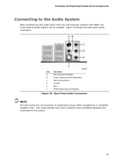
... to the Audio System After installing the IDT audio driver from the Intel Express Installer DVD-ROM, the multi-channel audio feature can be enabled. Installing and Replacing Desktop Board Components Connecting to this output. 45 Back Panel Audio Connectors NOTE The back panel line out connector is designed to power either headphones or amplified...
... to the Audio System After installing the IDT audio driver from the Intel Express Installer DVD-ROM, the multi-channel audio feature can be enabled. Installing and Replacing Desktop Board Components Connecting to this output. 45 Back Panel Audio Connectors NOTE The back panel line out connector is designed to power either headphones or amplified...


