Product Guide
Page 3
... configuring your system for Intel Rapid Recover Technology A Error Messages and Indicators: information about board layout, component installation, BIOS update, and regulatory requirements for installation in homes, offices, schools, computer rooms, and similar locations. iii The suitability of this product for other PC or embedded non-PC applications or other environments, such as follows: 1 Desktop Board Features: a summary of product features 2 Installing and Replacing Desktop Board Components: instructions...
... configuring your system for Intel Rapid Recover Technology A Error Messages and Indicators: information about board layout, component installation, BIOS update, and regulatory requirements for installation in homes, offices, schools, computer rooms, and similar locations. iii The suitability of this product for other PC or embedded non-PC applications or other environments, such as follows: 1 Desktop Board Features: a summary of product features 2 Installing and Replacing Desktop Board Components: instructions...
Product Guide
Page 5
... Serial ATA Auto Configuration 20 PCI Express* Auto Configuration 20 Security Passwords 20 Hardware Management Features 21 Fan Speed, Thermal, and Voltage Monitoring and Control 21 Chassis Intrusion 21 Power Management Features 22 ACPI ...22 Hardware Support 22 Power Connectors 22 Fan Headers 23 LAN Wake Capabilities 23 Instantly Available PC Technology 23 +5 V Standby Power Indicator 24 Wake from USB 24 WAKE# Signal Wake-up Support 25 Wake from CIR 25 ENERGY STAR* Qualified 25 Speaker...25 Battery ...25 Real-Time Clock 25 2 Installing and Replacing Desktop Board...
... Serial ATA Auto Configuration 20 PCI Express* Auto Configuration 20 Security Passwords 20 Hardware Management Features 21 Fan Speed, Thermal, and Voltage Monitoring and Control 21 Chassis Intrusion 21 Power Management Features 22 ACPI ...22 Hardware Support 22 Power Connectors 22 Fan Headers 23 LAN Wake Capabilities 23 Instantly Available PC Technology 23 +5 V Standby Power Indicator 24 Wake from USB 24 WAKE# Signal Wake-up Support 25 Wake from CIR 25 ENERGY STAR* Qualified 25 Speaker...25 Battery ...25 Real-Time Clock 25 2 Installing and Replacing Desktop Board...
Product Guide
Page 6
... Installing and Removing Memory 36 Installing DIMMs 37 Removing DIMMs 39 Connecting Serial ATA (SATA) Cables 40 Connecting to Internal Headers and Connectors 41 Front Panel HD Audio Header 42 Chassis Intrusion Header 42 Consumer IR (CIR) Headers 42 USB 2.0 Headers 43 Serial Port Header 44 Alternate Front Panel Power LED Header 44 Front Panel Header 44 Connecting to the Audio System 45 Connecting Chassis Fan and Power Supply Cables 46 Chassis Fan Cables 46 Power Supply Cables 47 Setting the BIOS Configuration Jumper 48 Clearing Passwords 49 Replacing the Battery 50 3 Updating...
... Installing and Removing Memory 36 Installing DIMMs 37 Removing DIMMs 39 Connecting Serial ATA (SATA) Cables 40 Connecting to Internal Headers and Connectors 41 Front Panel HD Audio Header 42 Chassis Intrusion Header 42 Consumer IR (CIR) Headers 42 USB 2.0 Headers 43 Serial Port Header 44 Alternate Front Panel Power LED Header 44 Front Panel Header 44 Connecting to the Audio System 45 Connecting Chassis Fan and Power Supply Cables 46 Chassis Fan Cables 46 Power Supply Cables 47 Setting the BIOS Configuration Jumper 48 Clearing Passwords 49 Replacing the Battery 50 3 Updating...
Product Guide
Page 7
LAN Status LEDs 18 3. Lift the Load Plate 32 8. Remove the Protective Socket Cover 32 9. Connecting a Serial ATA Cable 40 17. Internal Headers and Connectors 41 18. Back Panel Audio Connectors 45 19. Lift the Socket Lever 31 7. Remove the Processor from the Protective Processor Cover 33 10. Dual Channel Memory Configuration Example 36 14. Installing a DIMM 38 16. Contents A Error Messages and Indicators BIOS Beep Codes 65 BIOS Error Messages 65 B Regulatory Compliance Safety Standards 67 Place Battery Marking 67...
LAN Status LEDs 18 3. Lift the Load Plate 32 8. Remove the Protective Socket Cover 32 9. Connecting a Serial ATA Cable 40 17. Internal Headers and Connectors 41 18. Back Panel Audio Connectors 45 19. Lift the Socket Lever 31 7. Remove the Processor from the Protective Processor Cover 33 10. Dual Channel Memory Configuration Example 36 14. Installing a DIMM 38 16. Contents A Error Messages and Indicators BIOS Beep Codes 65 BIOS Error Messages 65 B Regulatory Compliance Safety Standards 67 Place Battery Marking 67...
Product Guide
Page 9
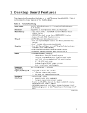
... (CIR) support ― One serial port via an onboard header • Up to 10 USB 2.0 ports ― Six ports routed to the back panel ― Four ports routed to two onboard headers • Five Serial ATA (SATA) channels (3.0 Gb/s) via ICH10R including one external SATA (eSATA) channel • SATA RAID support via Intel® Matrix Storage Technology (Intel® MST) including support for Intel® Rapid Recover Technology (Intel® RRT) continued 9 Feature Summary Form Factor Processor Main Memory Chipset Graphics Audio Mini-ITX...
... (CIR) support ― One serial port via an onboard header • Up to 10 USB 2.0 ports ― Six ports routed to the back panel ― Four ports routed to two onboard headers • Five Serial ATA (SATA) channels (3.0 Gb/s) via ICH10R including one external SATA (eSATA) channel • SATA RAID support via Intel® Matrix Storage Technology (Intel® MST) including support for Intel® Rapid Recover Technology (Intel® RRT) continued 9 Feature Summary Form Factor Processor Main Memory Chipset Graphics Audio Mini-ITX...
Product Guide
Page 10
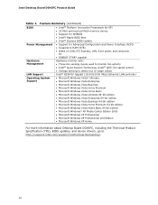
Intel Desktop Board DG45FC Product Guide Table 1. Feature Summary (continued) BIOS • Intel® Platform Innovation Framework for EFI • 32 Mbit symmetrical flash memory device • Support for SMBIOS • Intel® Rapid BIOS Boot • Intel® Express BIOS Update Power Management • Support for Advanced Configuration and Power Interface (ACPI) • Suspend to RAM (STR) • Wake on USB, PCI Express, LAN, front panel, and consumer IR • ENERGY STAR* capable Hardware Management Hardware monitor with: • Three fan sensing...
Intel Desktop Board DG45FC Product Guide Table 1. Feature Summary (continued) BIOS • Intel® Platform Innovation Framework for EFI • 32 Mbit symmetrical flash memory device • Support for SMBIOS • Intel® Rapid BIOS Boot • Intel® Express BIOS Update Power Management • Support for Advanced Configuration and Power Interface (ACPI) • Suspend to RAM (STR) • Wake on USB, PCI Express, LAN, front panel, and consumer IR • ENERGY STAR* capable Hardware Management Hardware monitor with: • Three fan sensing...
Product Guide
Page 13
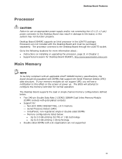
... BIOS will see a notification to the following locations for more information about: • Instructions on the screen at power up. Processors are not included with x16 organization are not supported 13 Desktop Board Features Processor CAUTION Failure to use an appropriate power supply and/or not connecting the 12 V (2 x 2 pin) power connector to the Desktop Board may result in damage to the Desktop Board through the LGA775 socket. The Desktop Board supports the dual or single channel memory configurations defined...
... BIOS will see a notification to the following locations for more information about: • Instructions on the screen at power up. Processors are not included with x16 organization are not supported 13 Desktop Board Features Processor CAUTION Failure to use an appropriate power supply and/or not connecting the 12 V (2 x 2 pin) power connector to the Desktop Board may result in damage to the Desktop Board through the LGA775 socket. The Desktop Board supports the dual or single channel memory configurations defined...
Product Guide
Page 17
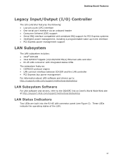
...-45 LAN connector panel (see Figure 2). Desktop Board Features Legacy Input/Output (I/O) Controller The I/O controller features the following: • Low pin count (LPC) interface • One serial port interface via an onboard header • Consumer Infrared (CIR) support • Serial IRQ interface compatible with serialized IRQ support for PCI Express systems • Intelligent power management, including a programmable wake up event interface • PCI Express power management support LAN Subsystem The LAN subsystem includes: • Intel® ICH10R • Intel 82567LF...
...-45 LAN connector panel (see Figure 2). Desktop Board Features Legacy Input/Output (I/O) Controller The I/O controller features the following: • Low pin count (LPC) interface • One serial port interface via an onboard header • Consumer Infrared (CIR) support • Serial IRQ interface compatible with serialized IRQ support for PCI Express systems • Intelligent power management, including a programmable wake up event interface • PCI Express power management support LAN Subsystem The LAN subsystem includes: • Intel® ICH10R • Intel 82567LF...
Product Guide
Page 19
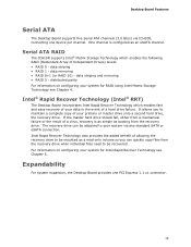
Desktop Board Features Serial ATA The Desktop Board supports five Serial ATA channels (3.0 Gb/s) via any standard SATA or eSATA connection. One channel is as simple as booting from the recovery drive. Serial ATA RAID The ICH10R supports Intel® Matrix Storage Technology which enables fast and easy recovery of your data in the event of a virus, recovery is configured as a read-only volume so you to your system for Intel Rapid Recover Technology see Chapter 4. data...
Desktop Board Features Serial ATA The Desktop Board supports five Serial ATA channels (3.0 Gb/s) via any standard SATA or eSATA connection. One channel is as simple as booting from the recovery drive. Serial ATA RAID The ICH10R supports Intel® Matrix Storage Technology which enables fast and easy recovery of your data in the event of a virus, recovery is configured as a read-only volume so you to your system for Intel Rapid Recover Technology see Chapter 4. data...
Product Guide
Page 20
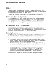
... you install a Serial ATA device (such as a hard drive) in your computer. Intel Desktop Board DG45FC Product Guide BIOS The BIOS provides the Power-On Self-Test (POST), the BIOS Setup program, the PCI Express and SATA auto-configuration utilities, and the video BIOS. The BIOS can override the auto-configuration options by following restrictions: • The supervisor password gives unrestricted access to run the BIOS Setup program after installing a Serial ATA device. You can be accessed and who can enter either the supervisor password or the user password to boot...
... you install a Serial ATA device (such as a hard drive) in your computer. Intel Desktop Board DG45FC Product Guide BIOS The BIOS provides the Power-On Self-Test (POST), the BIOS Setup program, the PCI Express and SATA auto-configuration utilities, and the video BIOS. The BIOS can override the auto-configuration options by following restrictions: • The supervisor password gives unrestricted access to run the BIOS Setup program after installing a Serial ATA device. You can be accessed and who can enter either the supervisor password or the user password to boot...
Product Guide
Page 21
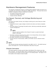
... control features include the following: • Monitoring of power supply voltages to detect levels above this point. The security feature uses a mechanical switch on the chassis that can adjust fan speed according to thermal conditions. • Fan speed controllers and sensors integrated into the ICH10R • Thermal sensors in the Channel A socket to enable Intel Quiet System Technology. • Thermally monitored closed-loop fan control, for the location of the chassis intrusion header. 21 Desktop Board...
... control features include the following: • Monitoring of power supply voltages to detect levels above this point. The security feature uses a mechanical switch on the chassis that can adjust fan speed according to thermal conditions. • Fan speed controllers and sensors integrated into the ICH10R • Thermal sensors in the Channel A socket to enable Intel Quiet System Technology. • Thermally monitored closed-loop fan control, for the location of the chassis intrusion header. 21 Desktop Board...
Product Guide
Page 22
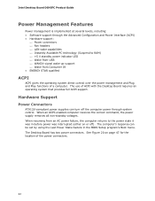
... Configuration and Power Interface (ACPI) • Hardware support: ⎯ Power connectors ⎯ Fan headers ⎯ LAN wake capabilities ⎯ Instantly Available PC technology (Suspend to the power state it was in the BIOS Setup program's Boot menu. When an ACPI-enabled computer receives the correct command, the power supply removes all non-standby voltages. When resuming from an AC power failure, the computer returns to RAM) ⎯ +5 V standby power indicator LED ⎯ Wake from USB ⎯ WAKE# signal wake-up support ⎯ Wake...
... Configuration and Power Interface (ACPI) • Hardware support: ⎯ Power connectors ⎯ Fan headers ⎯ LAN wake capabilities ⎯ Instantly Available PC technology (Suspend to the power state it was in the BIOS Setup program's Boot menu. When an ACPI-enabled computer receives the correct command, the power supply removes all non-standby voltages. When resuming from an AC power failure, the computer returns to RAM) ⎯ +5 V standby power indicator LED ⎯ Wake from USB ⎯ WAKE# signal wake-up support ⎯ Wake...
Product Guide
Page 23
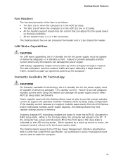
...; All fan headers have a +12 V DC connection. The Desktop Board supports the PCI Bus Power Management Interface Specification. Add-in the S3 sleep state, the computer will appear to wake the computer. 23 The Desktop Board has a 4-pin processor fan header and a 3-pin chassis fan header. Instantly Available PC Technology CAUTIONS For Instantly Available PC technology, the 5 V standby line for the power supply must be used to be capable of the computer through a network. While in cards that powers up...
...; All fan headers have a +12 V DC connection. The Desktop Board supports the PCI Bus Power Management Interface Specification. Add-in the S3 sleep state, the computer will appear to wake the computer. 23 The Desktop Board has a 4-pin processor fan header and a 3-pin chassis fan header. Instantly Available PC Technology CAUTIONS For Instantly Available PC technology, the 5 V standby line for the power supply must be used to be capable of the computer through a network. While in cards that powers up...
Product Guide
Page 27
... and attaching it to operate even though the front panel power button is not available, you how to: • Install the I/O shield • Install and remove the Desktop Board • Install and remove a processor • Install and remove memory • Connect the Serial ATA cables • Connect to the internal headers • Connect to the onboard audio system • Connect chassis fan and power supply cables • Set the BIOS configuration jumper • Clear passwords • Replace the battery Before You Begin CAUTIONS The procedures in personal...
... and attaching it to operate even though the front panel power button is not available, you how to: • Install the I/O shield • Install and remove the Desktop Board • Install and remove a processor • Install and remove memory • Connect the Serial ATA cables • Connect to the internal headers • Connect to the onboard audio system • Connect chassis fan and power supply cables • Set the BIOS configuration jumper • Clear passwords • Replace the battery Before You Begin CAUTIONS The procedures in personal...
Product Guide
Page 35
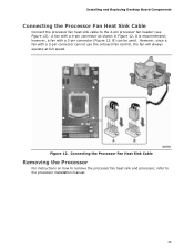
..., B) can be used. Installing and Replacing Desktop Board Components Connecting the Processor Fan Heat Sink Cable Connect the processor fan heat sink cable to the processor installation manual. 35 Figure 12. Connecting the Processor Fan Heat Sink Cable Removing the Processor For instructions on how to remove the processor fan heat sink and processor, refer to the 4-pin processor fan header (see Figure 12). however, a fan with a 4-pin connector as shown in Figure 12, A is recommended; However, since a fan with a 3-pin connector cannot use the onboard fan control, the fan will always...
..., B) can be used. Installing and Replacing Desktop Board Components Connecting the Processor Fan Heat Sink Cable Connect the processor fan heat sink cable to the processor installation manual. 35 Figure 12. Connecting the Processor Fan Heat Sink Cable Removing the Processor For instructions on how to remove the processor fan heat sink and processor, refer to the 4-pin processor fan header (see Figure 12). however, a fan with a 4-pin connector as shown in Figure 12, A is recommended; However, since a fan with a 3-pin connector cannot use the onboard fan control, the fan will always...
Product Guide
Page 49
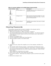
... power adapter). 3. Jumper Settings for the BIOS Setup Program Modes Jumper Setting Mode Normal (default) (1-2) Description The BIOS uses the current configuration and passwords for booting. Select Yes and press . Installing and Replacing Desktop Board Components Table 13. Clearing Passwords This procedure assumes that you confirm clearing the password. The BIOS recovers data in the computer and the configuration jumper block is set to boot. 7. Disconnect the computer's power cord from the AC power source. 11. Press and Setup displays a pop-up screen...
... power adapter). 3. Jumper Settings for the BIOS Setup Program Modes Jumper Setting Mode Normal (default) (1-2) Description The BIOS uses the current configuration and passwords for booting. Select Yes and press . Installing and Replacing Desktop Board Components Table 13. Clearing Passwords This procedure assumes that you confirm clearing the password. The BIOS recovers data in the computer and the configuration jumper block is set to boot. 7. Disconnect the computer's power cord from the AC power source. 11. Press and Setup displays a pop-up screen...
Product Guide
Page 55
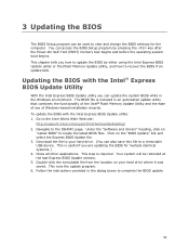
... key after the Power-On Self-Test (POST) memory test begins and before the operating system boot begins. This chapter tells you how to recover the BIOS if an update fails. Under the "Software and drivers" heading, click on "Latest BIOS" to a removable USB device. 3 Updating the BIOS The BIOS Setup program can be rebooted at the last Express BIOS Update window. 5. To update the BIOS with the Intel® Express BIOS Update Utility With the Intel Express BIOS Update utility you are updating...
... key after the Power-On Self-Test (POST) memory test begins and before the operating system boot begins. This chapter tells you how to recover the BIOS if an update fails. Under the "Software and drivers" heading, click on "Latest BIOS" to a removable USB device. 3 Updating the BIOS The BIOS Setup program can be rebooted at the last Express BIOS Update window. 5. To update the BIOS with the Intel® Express BIOS Update Utility With the Intel Express BIOS Update utility you are updating...
Product Guide
Page 58
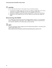
...://support.intel.com/support/motherboards/desktop/sb/CS-022312.htm. 58 Configure the BIOS or use the F10 option during POST to boot to a bootable USB flash drive or other bootable USB media. 2. Uncompress the BIOS update file and copy the .BIO file, IFLASH.EXE, and .ITK file (optional) to the USB device. 3. however, if an interruption occurs, the BIOS could be required. NOTE For more information about updating the Intel Desktop Board BIOS or recovering from the USB device and manually update the BIOS. Intel Desktop Board DG45FC Product Guide...
...://support.intel.com/support/motherboards/desktop/sb/CS-022312.htm. 58 Configure the BIOS or use the F10 option during POST to boot to a bootable USB flash drive or other bootable USB media. 2. Uncompress the BIOS update file and copy the .BIO file, IFLASH.EXE, and .ITK file (optional) to the USB device. 3. however, if an interruption occurs, the BIOS could be required. NOTE For more information about updating the Intel Desktop Board BIOS or recovering from the USB device and manually update the BIOS. Intel Desktop Board DG45FC Product Guide...
Product Guide
Page 60
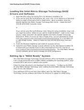
... Matrix Storage Technology RAID Driver. or If you will be used to upgrade from this section: "Configuring the BIOS for Intel Matrix Storage Technology" and "Loading the Intel Matrix Storage Technology RAID Drivers and Software". Begin Windows Setup by booting from the Internet at the beginning of Windows Setup to a RAID setup. 60 Install the Intel® ICH10R SATA RAID Controller driver. Select to a recordable CD or USB storage media). Install the Intel Matrix Storage Console software via the Intel Express Installer CD included with your desktop board or after downloading it...
... Matrix Storage Technology RAID Driver. or If you will be used to upgrade from this section: "Configuring the BIOS for Intel Matrix Storage Technology" and "Loading the Intel Matrix Storage Technology RAID Drivers and Software". Begin Windows Setup by booting from the Internet at the beginning of Windows Setup to a RAID setup. 60 Install the Intel® ICH10R SATA RAID Controller driver. Select to a recordable CD or USB storage media). Install the Intel Matrix Storage Console software via the Intel Express Installer CD included with your desktop board or after downloading it...
Product Guide
Page 61
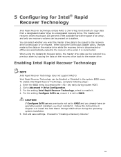
... installed, you want the master drive data to be present on the recovery drive back to Advanced Drive Configuration. 3. Intel Rapid Recover Technology can be Enabled or Disabled in Chapter 4 to "Creating a Recovery Volume." 61 Follow the instructions in the system BIOS menu. Proceed to install the Intel Matrix Storage RAID driver during system POST. 2. To enable Intel Rapid Recover Technology, complete following steps: 1. Enter the BIOS menu by copying the data on a system. CAUTION If Configure SATA...
... installed, you want the master drive data to be present on the recovery drive back to Advanced Drive Configuration. 3. Intel Rapid Recover Technology can be Enabled or Disabled in Chapter 4 to "Creating a Recovery Volume." 61 Follow the instructions in the system BIOS menu. Proceed to install the Intel Matrix Storage RAID driver during system POST. 2. To enable Intel Rapid Recover Technology, complete following steps: 1. Enter the BIOS menu by copying the data on a system. CAUTION If Configure SATA...


