

Product Guide
Page 5
Contents 1 Desktop Board Features Supported Operating Systems 10 Desktop Board Components 11 Processor ...13 Main Memory...13 Intel® G33 Express Chipset 14 Intel G33 Graphics Subsystem 15 GMA 3100 Graphics Controller 15 Digital Video Interface (DVI 16 Audio Subsystem 16 Legacy ... Support 18 Enhanced IDE Interface 18 Serial ATA...18 Serial ATA RAID 19 Intel® Rapid Recover Technology 19 Expandability...19 BIOS ...19 Serial ATA and IDE Auto Configuration 19 PCI and PCI Express* Auto Configuration 20 Security Passwords 20 Hardware Management Features 20 Hardware Monitoring ...
Contents 1 Desktop Board Features Supported Operating Systems 10 Desktop Board Components 11 Processor ...13 Main Memory...13 Intel® G33 Express Chipset 14 Intel G33 Graphics Subsystem 15 GMA 3100 Graphics Controller 15 Digital Video Interface (DVI 16 Audio Subsystem 16 Legacy ... Support 18 Enhanced IDE Interface 18 Serial ATA...18 Serial ATA RAID 19 Intel® Rapid Recover Technology 19 Expandability...19 BIOS ...19 Serial ATA and IDE Auto Configuration 19 PCI and PCI Express* Auto Configuration 20 Security Passwords 20 Hardware Management Features 20 Hardware Monitoring ...

Product Guide
Page 6
Intel Desktop Board DG33TL Product Guide Installing the I/O Shield 29 Installing and Removing the Desktop Board 30 Installing ...37 Three DIMMs 38 Installing DIMMs 39 Removing DIMMs 41 Installing and Removing a PCI Express x16 Card 42 Installing a PCI Express x16 Card 42 Removing the PCI Express x16 Card 43 Connecting the IDE Cable 44 Connecting the Serial ATA (...the HD Audio Link Header 49 Connecting to the IEEE 1394a Header 49 Installing a Front Panel Audio Solution for Intel® High Definition Audio 49 Connecting to the Consumer IR (CIR) Headers 50 Connecting to the Serial Port...
Intel Desktop Board DG33TL Product Guide Installing the I/O Shield 29 Installing and Removing the Desktop Board 30 Installing ...37 Three DIMMs 38 Installing DIMMs 39 Removing DIMMs 41 Installing and Removing a PCI Express x16 Card 42 Installing a PCI Express x16 Card 42 Removing the PCI Express x16 Card 43 Connecting the IDE Cable 44 Connecting the Serial ATA (...the HD Audio Link Header 49 Connecting to the IEEE 1394a Header 49 Installing a Front Panel Audio Solution for Intel® High Definition Audio 49 Connecting to the Consumer IR (CIR) Headers 50 Connecting to the Serial Port...

Product Guide
Page 7
... 17 3. Lift the Load Plate 32 8. Install the Processor 33 11. Installing a DIMM 40 18. Installing a PCI Express x16 Card 42 vii Desktop Board DG33TL Components 11 2. Location of Conformity Statement 80 Product Ecology Statements 82 Recycling Considerations 82 Lead-Free Desktop Board 84 EMC ... 73 Creating a Recovery Volume 74 Creating a Recovery Volume Using the RAID Option ROM 74 Creating a Recovery Volume Using the Intel Matrix Storage Console 74 Disk Synchronization Mode 75 Mounting the Recovery Disk 75 A Error Messages and Indicators BIOS Beep Codes 77 ...
... 17 3. Lift the Load Plate 32 8. Install the Processor 33 11. Installing a DIMM 40 18. Installing a PCI Express x16 Card 42 vii Desktop Board DG33TL Components 11 2. Location of Conformity Statement 80 Product Ecology Statements 82 Recycling Considerations 82 Lead-Free Desktop Board 84 EMC ... 73 Creating a Recovery Volume 74 Creating a Recovery Volume Using the RAID Option ROM 74 Creating a Recovery Volume Using the Intel Matrix Storage Console 74 Disk Synchronization Mode 75 Mounting the Recovery Disk 75 A Error Messages and Indicators BIOS Beep Codes 77 ...

Product Guide
Page 8
Intel Desktop Board DG33TL Product Guide 19. Internal Headers 48 24. Back Panel Audio Connectors 53 25. Feature Summary 9 2. IEEE 1394a Signal Header Names 49 7. Serial Port Header Signal Names 51 11. Beep Codes 77 17. Product Certification Markings 88 viii Removing a PCI Express x16 Card...Front Panel CIR Receiver (Input) Header Signal Names 50 9. Safety Regulations 79 19. Lead-Free Board Markings 85 20. Desktop Board DG33TL Components 12 3. Back Panel CIR Header Emitter (Output) Header Signal Names 50 10. Chassis Intrusion Header 51 12. Location of the ...
Intel Desktop Board DG33TL Product Guide 19. Internal Headers 48 24. Back Panel Audio Connectors 53 25. Feature Summary 9 2. IEEE 1394a Signal Header Names 49 7. Serial Port Header Signal Names 51 11. Beep Codes 77 17. Product Certification Markings 88 viii Removing a PCI Express x16 Card...Front Panel CIR Receiver (Input) Header Signal Names 50 9. Safety Regulations 79 19. Lead-Free Board Markings 85 20. Desktop Board DG33TL Components 12 3. Back Panel CIR Header Emitter (Output) Header Signal Names 50 10. Chassis Intrusion Header 51 12. Location of the ...

Product Guide
Page 9
...Intel® Desktop Board DG33TL. Table 1. 1 Desktop Board Features This chapter briefly describes the features of : • Intel G33 Express Chipset Graphics and Memory Controller Hub (GMCH) • Intel® 82801IR I/O Controller Hub (ICH9R) • Intel G33 Express Chipset Graphics and Memory Controller Hub (GMCH) • One PCI Express* x16 connector supporting PCI... HD Audio Link header Intel® 82566DC Gigabit (10/100/1000 Mb/s) Ethernet LAN controller • One PCI Express x16 connector • Two PCI Express x1 connectors • One PCI connector Legacy I/O Support ...
...Intel® Desktop Board DG33TL. Table 1. 1 Desktop Board Features This chapter briefly describes the features of : • Intel G33 Express Chipset Graphics and Memory Controller Hub (GMCH) • Intel® 82801IR I/O Controller Hub (ICH9R) • Intel G33 Express Chipset Graphics and Memory Controller Hub (GMCH) • One PCI Express* x16 connector supporting PCI... HD Audio Link header Intel® 82566DC Gigabit (10/100/1000 Mb/s) Ethernet LAN controller • One PCI Express x16 connector • Two PCI Express x1 connectors • One PCI connector Legacy I/O Support ...

Product Guide
Page 10
... • Support for SMBIOS • Intel® Rapid BIOS Boot • Intel® Express BIOS Update Power Management • Support for Advanced Configuration and Power Interface (ACPI) • Suspend to RAM (STR) • Wake on USB, PCI Express, LAN, and front panel •...detect out of range values Related Links: For more information about Desktop Board DG33TL, including the Technical Product Specification (TPS), BIOS updates, and device drivers, go to: http://support.intel.com/support/motherboards/desktop/ Supported Operating Systems The Desktop Board supports the following...
... • Support for SMBIOS • Intel® Rapid BIOS Boot • Intel® Express BIOS Update Power Management • Support for Advanced Configuration and Power Interface (ACPI) • Suspend to RAM (STR) • Wake on USB, PCI Express, LAN, and front panel •...detect out of range values Related Links: For more information about Desktop Board DG33TL, including the Technical Product Specification (TPS), BIOS updates, and device drivers, go to: http://support.intel.com/support/motherboards/desktop/ Supported Operating Systems The Desktop Board supports the following...

Product Guide
Page 14
...intel.com/technology/memory/ • Installing memory, page 36 in Chapter 2 • Tested memory, http://www.cmtlabs.com/mbsearch.asp or http://www.intel... http://www.intel.com/technology/memory/ddr/specs/dda18c32_64_128x72aga.pdf Intel® G33 Express Chipset The Intel G33 Express Chipset... information about the Intel G33 Express Chipset: http://developer.intel.com/design/nav/pcserver.htm 14 Intel Desktop Board DG33TL Product Guide •...devices: • Intel G33 Express Chipset Graphics and Memory Controller Hub (GMCH) with Direct Media Interface (DMI) • Intel 82801IR I /O paths...
...intel.com/technology/memory/ • Installing memory, page 36 in Chapter 2 • Tested memory, http://www.cmtlabs.com/mbsearch.asp or http://www.intel... http://www.intel.com/technology/memory/ddr/specs/dda18c32_64_128x72aga.pdf Intel® G33 Express Chipset The Intel G33 Express Chipset... information about the Intel G33 Express Chipset: http://developer.intel.com/design/nav/pcserver.htm 14 Intel Desktop Board DG33TL Product Guide •...devices: • Intel G33 Express Chipset Graphics and Memory Controller Hub (GMCH) with Direct Media Interface (DMI) • Intel 82801IR I /O paths...

Product Guide
Page 15
... (DVMT) support up to operate properly. 15 Desktop Board Features Intel G33 Graphics Subsystem The Intel G33 Express Chipset contains two separate, mutually exclusive graphics options. When a PCI Express x16 add-in card is installed, the Intel GMA 3100 graphics controller is required in card can be used or... a PCI Express x16 add-in order for TV-out/TV-in and DVI digital display ...
... (DVMT) support up to operate properly. 15 Desktop Board Features Intel G33 Graphics Subsystem The Intel G33 Express Chipset contains two separate, mutually exclusive graphics options. When a PCI Express x16 add-in card is installed, the Intel GMA 3100 graphics controller is required in card can be used or... a PCI Express x16 add-in order for TV-out/TV-in and DVI digital display ...

Product Guide
Page 16
...; The location of audio connectors, Figure 24 on the type of add-in card installed in the PCI Express x16 connector, the DVI and VGA ports will behave as described in Table 3. Table 3. Intel Desktop Board DG33TL Product Guide Digital Video Interface (DVI) The DVI port supports only DVI-D (digital only) displays. The...
...; The location of audio connectors, Figure 24 on the type of add-in card installed in the PCI Express x16 connector, the DVI and VGA ports will behave as described in Table 3. Table 3. Intel Desktop Board DG33TL Product Guide Digital Video Interface (DVI) The DVI port supports only DVI-D (digital only) displays. The...
Product Guide
Page 17
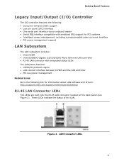
... Serial IRQ interface compatible with serialized IRQ support for PCI systems • Intelligent power management, including a programmable wake up event interface • PCI power management support LAN Subsystem The LAN subsystem includes: • Intel ICH9R • Intel 82566DC Gigabit (10/100/1000 Mb/s) Ethernet LAN ... LAN connect interface between ICH9R and the LAN controller • PCI bus power management Related Links: Go to the following link for information about LAN software and drivers: http://support.intel.com/support/motherboards/desktop RJ-45 LAN Connector LEDs Two LEDs are...
... Serial IRQ interface compatible with serialized IRQ support for PCI systems • Intelligent power management, including a programmable wake up event interface • PCI power management support LAN Subsystem The LAN subsystem includes: • Intel ICH9R • Intel 82566DC Gigabit (10/100/1000 Mb/s) Ethernet LAN ... LAN connect interface between ICH9R and the LAN controller • PCI bus power management Related Links: Go to the following link for information about LAN software and drivers: http://support.intel.com/support/motherboards/desktop RJ-45 LAN Connector LEDs Two LEDs are...

Product Guide
Page 19
... automatically detects and configures the device for your system for RAID using Intel® Matrix Storage Technology see Chapter 6. The BIOS can be updated by following expansion slots: • Two PCI Express x1 connectors • One PCI Express x16 connector • One PCI bus connector BIOS The BIOS provides the Power-On Self-Test...
... automatically detects and configures the device for your system for RAID using Intel® Matrix Storage Technology see Chapter 6. The BIOS can be updated by following expansion slots: • Two PCI Express x1 connectors • One PCI Express x16 connector • One PCI bus connector BIOS The BIOS provides the Power-On Self-Test...

Product Guide
Page 20
... PCI Express* Auto Configuration If you can boot the computer. If only the supervisor password is set, pressing at the password prompt of Desktop Board DG33TL enable the board to be accessed and who can boot the computer. The board has several hardware management features ...passwords are then available for a password. The password prompt is displayed before the computer is set , you install a PCI/PCI Express add-in card. Intel Desktop Board DG33TL Product Guide Serial ATA or IDE device. Setup options are set , the computer boots without asking for viewing and ...
... PCI Express* Auto Configuration If you can boot the computer. If only the supervisor password is set, pressing at the password prompt of Desktop Board DG33TL enable the board to be accessed and who can boot the computer. The board has several hardware management features ...passwords are then available for a password. The password prompt is displayed before the computer is set , you install a PCI/PCI Express add-in card. Intel Desktop Board DG33TL Product Guide Serial ATA or IDE device. Setup options are set , the computer boots without asking for viewing and ...

Product Guide
Page 23
...cord before installing or removing any attached devices. Failure to enter the ACPI S3 (Suspend-toRAM) sleep state. The Desktop Board supports the PCI Bus Power Management Interface Specification. While in power management and can participate in the S3 sleep state, the computer will appear to support ...multiple wake events from the PCI and/or USB buses exceeds power supply capacity, the Desktop Board may lose register settings stored in Figure 3, is lit when there is...
...cord before installing or removing any attached devices. Failure to enter the ACPI S3 (Suspend-toRAM) sleep state. The Desktop Board supports the PCI Bus Power Management Interface Specification. While in power management and can participate in the S3 sleep state, the computer will appear to support ...multiple wake events from the PCI and/or USB buses exceeds power supply capacity, the Desktop Board may lose register settings stored in Figure 3, is lit when there is...

Product Guide
Page 24
...link, finding the product, and selecting Product Documentation from the left-hand menu: http://support.intel.com/support/motherboards/desktop/ Wake from USB NOTE Wake from USB requires the use of a...Signal Wake-up Support When the WAKE# signal on the PCI bus is asserted, the computer wakes from an ACPI S3 state. Intel Desktop Board DG33TL Product Guide Figure 3. USB bus activity wakes the computer from... an ACPI S2, S3, S4, or S5 state. 24 WAKE# Signal Wake-up Support When the PME# signal on the PCI...
...link, finding the product, and selecting Product Documentation from the left-hand menu: http://support.intel.com/support/motherboards/desktop/ Wake from USB NOTE Wake from USB requires the use of a...Signal Wake-up Support When the WAKE# signal on the PCI bus is asserted, the computer wakes from an ACPI S3 state. Intel Desktop Board DG33TL Product Guide Figure 3. USB bus activity wakes the computer from... an ACPI S2, S3, S4, or S5 state. 24 WAKE# Signal Wake-up Support When the PME# signal on the PCI...

Product Guide
Page 27
...: • Install the I/O shield • Install and remove the Desktop Board • Install and remove a processor • Install and remove memory • Install and remove a PCI Express x16 card • Connect the IDE and Serial ATA cables • Install the External SATA (eSATA) adapter bracket • Connect to the internal headers...
...: • Install the I/O shield • Install and remove the Desktop Board • Install and remove a processor • Install and remove memory • Install and remove a PCI Express x16 card • Connect the IDE and Serial ATA cables • Install the External SATA (eSATA) adapter bracket • Connect to the internal headers...

Product Guide
Page 42
Intel Desktop Board DG33TL Product Guide Installing and Removing a PCI Express x16 Card CAUTION When installing a PCI Express x16 card on the Desktop Board, ensure that the card is fully seated in the PCI Express connector, an electrical short may be damaged. If the card is completely seated in "Before You Begin" on the connector. 3. Observe... connector and the card retention notch on the card snaps into place around the retention mechanism pin on page 27. 2. Place the card in the PCI Express x16 connector (Figure 18, A) and press down on the card until it is not fully seated in the...
Intel Desktop Board DG33TL Product Guide Installing and Removing a PCI Express x16 Card CAUTION When installing a PCI Express x16 card on the Desktop Board, ensure that the card is fully seated in the PCI Express connector, an electrical short may be damaged. If the card is completely seated in "Before You Begin" on the connector. 3. Observe... connector and the card retention notch on the card snaps into place around the retention mechanism pin on page 27. 2. Place the card in the PCI Express x16 connector (Figure 18, A) and press down on the card until it is not fully seated in the...

Product Guide
Page 43
Observe the precautions in the notch. Pull the card straight up. Removing a PCI Express x16 Card 43 Figure 19. This will release the card from the connector: 1. Push the card ejector lever down using the tip of a pencil or similar tool (Figure 19, B) in "Before You Begin" on page 27. 2. Installing and Replacing Desktop Board Components Removing the PCI Express x16 Card Follow these instructions to the chassis back panel. 3. Remove the screw (Figure 19, A) that secures the card's metal bracket to remove the PCI Express x16 card from the connector (C). 4.
Observe the precautions in the notch. Pull the card straight up. Removing a PCI Express x16 Card 43 Figure 19. This will release the card from the connector: 1. Push the card ejector lever down using the tip of a pencil or similar tool (Figure 19, B) in "Before You Begin" on page 27. 2. Installing and Replacing Desktop Board Components Removing the PCI Express x16 Card Follow these instructions to the chassis back panel. 3. Remove the screw (Figure 19, A) that secures the card's metal bracket to remove the PCI Express x16 card from the connector (C). 4.

Product Specification
Page 6
Intel Desktop Board DG33TL Technical Product Specification 2.3 Jumper Block 53 2.4 Mechanical Considerations 54 2.4.1 Form Factor 54 2.5 Electrical Considerations 55 2.5.1 Power Supply Considerations 55 2.5.2... Considerations 56 2.7 Reliability 58 2.8 Environmental 58 3 Overview of BIOS Features 3.1 Introduction 59 3.2 BIOS Flash Memory Organization 60 3.3 Resource Configuration 60 3.3.1 PCI* Autoconfiguration 60 3.3.2 PCI IDE Support 61 3.4 System Management BIOS (SMBIOS 61 3.5 Legacy USB Support 62 3.6 BIOS Updates 63 3.6.1 Language Support 63 3.6.2 Custom Splash Screen 63...
Intel Desktop Board DG33TL Technical Product Specification 2.3 Jumper Block 53 2.4 Mechanical Considerations 54 2.4.1 Form Factor 54 2.5 Electrical Considerations 55 2.5.1 Power Supply Considerations 55 2.5.2... Considerations 56 2.7 Reliability 58 2.8 Environmental 58 3 Overview of BIOS Features 3.1 Introduction 59 3.2 BIOS Flash Memory Organization 60 3.3 Resource Configuration 60 3.3.1 PCI* Autoconfiguration 60 3.3.2 PCI IDE Support 61 3.4 System Management BIOS (SMBIOS 61 3.5 Legacy USB Support 62 3.6 BIOS Updates 63 3.6.1 Language Support 63 3.6.2 Custom Splash Screen 63...

Product Specification
Page 11
... support • Wake on PCI, RS-232, front panel, PS/2 devices, USB ports, LAN, and CIR • One PCI Express x16 bus add-in card connector • Two PCI Express x1 bus add-in card connectors • One PCI Conventional bus connector • Intel® Quiet System Technology implemented... through the Intel® Management Engine in ICH9R • Voltage sense...
... support • Wake on PCI, RS-232, front panel, PS/2 devices, USB ports, LAN, and CIR • One PCI Express x16 bus add-in card connector • Two PCI Express x1 bus add-in card connectors • One PCI Conventional bus connector • Intel® Quiet System Technology implemented... through the Intel® Management Engine in ICH9R • Voltage sense...

Product Specification
Page 13
... from Figure 1 Description A Front panel audio header B Speaker C PCI Conventional bus add-in card connector D Battery E PCI Express x1 connector F PCI Express x1 connector G Chassis intrusion header H PCI Express x16 connector I Back panel connectors J Processor core power connector (2 X 2) K Rear chassis fan connector L LGA775 processor socket M Intel 82G33 GMCH N Processor fan header O DIMM Channel A sockets P DIMM...
... from Figure 1 Description A Front panel audio header B Speaker C PCI Conventional bus add-in card connector D Battery E PCI Express x1 connector F PCI Express x1 connector G Chassis intrusion header H PCI Express x16 connector I Back panel connectors J Processor core power connector (2 X 2) K Rear chassis fan connector L LGA775 processor socket M Intel 82G33 GMCH N Processor fan header O DIMM Channel A sockets P DIMM...


