

Technical Product Specification
Page 8
... of BIOS Features 3.1 Introduction 55 3.2 BIOS Flash Memory Organization 56 3.3 System Management BIOS (SMBIOS 56 3.4 Legacy USB Support 56 3.5 BIOS Updates 57 3.5.1 Language Support 57 3.5.2 Custom Splash Screen 58 3.6 BIOS Recovery 58 3.7 Boot Options 59 3.7.1 Network Boot 59 3.7.2 Booting Without Attached Devices 59 3.7.3 Changing the Default Boot Device During POST 59 3.8 Hard Disk Drive Password Security Feature 60 3.9 BIOS Security Features 61 4 Error Messages and Blink Codes 4.1 Front-panel Power LED Blink Codes 63 4.2 BIOS Error Messages 63 4.3 Port 80h POST Codes 64...
... of BIOS Features 3.1 Introduction 55 3.2 BIOS Flash Memory Organization 56 3.3 System Management BIOS (SMBIOS 56 3.4 Legacy USB Support 56 3.5 BIOS Updates 57 3.5.1 Language Support 57 3.5.2 Custom Splash Screen 58 3.6 BIOS Recovery 58 3.7 Boot Options 59 3.7.1 Network Boot 59 3.7.2 Booting Without Attached Devices 59 3.7.3 Changing the Default Boot Device During POST 59 3.8 Hard Disk Drive Password Security Feature 60 3.9 BIOS Security Features 61 4 Error Messages and Blink Codes 4.1 Front-panel Power LED Blink Codes 63 4.2 BIOS Error Messages 63 4.3 Port 80h POST Codes 64...
Technical Product Specification
Page 9
... Power LED 44 16. Boot Device Menu Options 59 ix Components Shown in Figure 1 14 3. Dual-Port Front Panel USB 2.0 Header 42 13. 19 V Internal Power Supply Connector 43 14. BIOS Setup Configuration Jumper Settings 47 17. Contents 5.1.5 ENERGY STAR* 5.2, e-Standby, and ErP Compliance 78 5.1.6 Regulatory Compliance Marks (Board Level 79 5.2 Battery Disposal Information 80 Figures 1. Localized High Temperature Zones 51 Tables 1. Supported Memory Configurations 19 5. System Memory Map 37 10. Connectors and Headers Shown in Figure 10 40 11. Memory Channel...
... Power LED 44 16. Boot Device Menu Options 59 ix Components Shown in Figure 1 14 3. Dual-Port Front Panel USB 2.0 Header 42 13. 19 V Internal Power Supply Connector 43 14. BIOS Setup Configuration Jumper Settings 47 17. Contents 5.1.5 ENERGY STAR* 5.2, e-Standby, and ErP Compliance 78 5.1.6 Regulatory Compliance Marks (Board Level 79 5.2 Battery Disposal Information 80 Figures 1. Localized High Temperature Zones 51 Tables 1. Supported Memory Configurations 19 5. System Memory Map 37 10. Connectors and Headers Shown in Figure 10 40 11. Memory Channel...

Technical Product Specification
Page 10
Safety Standards 71 31. Supervisor and User Password Functions 61 25. Master Key and User Hard Drive Password Functions 60 24. Regulatory Compliance Marks 79 x EMC Regulations 75 32. BIOS Error Messages 63 27. Port 80h POST Codes 65 29. Typical Port 80h POST Sequence 69 30. Front-panel Power LED Blink Codes 63 26. Port 80h POST Code Ranges 64 28. Intel Desktop Board DCP847SKE Technical Product Specification 23.
Safety Standards 71 31. Supervisor and User Password Functions 61 25. Master Key and User Hard Drive Password Functions 60 24. Regulatory Compliance Marks 79 x EMC Regulations 75 32. BIOS Error Messages 63 27. Port 80h POST Codes 65 29. Typical Port 80h POST Sequence 69 30. Front-panel Power LED Blink Codes 63 26. Port 80h POST Code Ranges 64 28. Intel Desktop Board DCP847SKE Technical Product Specification 23.

Technical Product Specification
Page 11
... Intel® Graphics Technology: ― Two High Definition Multimedia Interface* (HDMI*) back panel connectors Intel® High Definition Audio via the HDMI v1.4a interfaces • USB 2.0 ports: ― Three front panel ports (via one dual-port internal header and one front panel connector) ― Two ports are implemented with vertical back panel connectors ― One port is reserved for the PCI Express* Half-Mini Card ― One port is reserved for the PCI Express Full-Mini Card • SATA port: ― One internal mSATA port (PCI Express...
... Intel® Graphics Technology: ― Two High Definition Multimedia Interface* (HDMI*) back panel connectors Intel® High Definition Audio via the HDMI v1.4a interfaces • USB 2.0 ports: ― Three front panel ports (via one dual-port internal header and one front panel connector) ― Two ports are implemented with vertical back panel connectors ― One port is reserved for the PCI Express* Half-Mini Card ― One port is reserved for the PCI Express Full-Mini Card • SATA port: ― One internal mSATA port (PCI Express...

Technical Product Specification
Page 18
...: http://www.intel.com/products/motherboard/index.htm http://www.intel.com/p/en_US/support?iid=hdr+support http://ark.intel.com Chipset information BIOS and driver updates Tested memory Integration information http://www.intel.com/products/desktop/chipsets/index.htm http://downloadcenter.intel.com http://www.intel.com/support/motherboards/desktop/sb/CS025414.htm http://www.intel.com/support/go/buildit 1.3 Processor The board has a soldered-down Intel Celeron processor 847 with Integrated Graphics Technology and integrated memory controller.
...: http://www.intel.com/products/motherboard/index.htm http://www.intel.com/p/en_US/support?iid=hdr+support http://ark.intel.com Chipset information BIOS and driver updates Tested memory Integration information http://www.intel.com/products/desktop/chipsets/index.htm http://downloadcenter.intel.com http://www.intel.com/support/motherboards/desktop/sb/CS025414.htm http://www.intel.com/support/go/buildit 1.3 Processor The board has a soldered-down Intel Celeron processor 847 with Integrated Graphics Technology and integrated memory controller.

Technical Product Specification
Page 19
If non-SPD memory is installed, the BIOS will attempt to correctly configure the memory settings, but performance and reliability may not function under the determined frequency. Table 5 lists the supported SO-DIMM configurations. Supported Memory Configurations Raw Card Version A SO-DIMM Capacity 1 GB 2 GB DRAM Device Technology 1 Gb 2 Gb DRAM Organization 64 M x 16 128 M x 16 # of DRAM Devices 8 8 1 GB B 2 GB 1 Gb 2 Gb 128 M x 8 8 256 M x 8 8 512 MB 1 Gb C 1 GB 2 Gb 64 M x 16...
If non-SPD memory is installed, the BIOS will attempt to correctly configure the memory settings, but performance and reliability may not function under the determined frequency. Table 5 lists the supported SO-DIMM configurations. Supported Memory Configurations Raw Card Version A SO-DIMM Capacity 1 GB 2 GB DRAM Device Technology 1 Gb 2 Gb DRAM Organization 64 M x 16 128 M x 16 # of DRAM Devices 8 8 1 GB B 2 GB 1 Gb 2 Gb 128 M x 8 8 256 M x 8 8 512 MB 1 Gb C 1 GB 2 Gb 64 M x 16...

Technical Product Specification
Page 24
... 15 1.7 SATA Interface The board provides one internal mSATA port (PCI Express Full-Mini Card connector) for configurations using Windows operating systems. 1.7.1 AHCI Mode The board supports AHCI storage mode via one dual-port internal header and one front panel connector) • Two ports are implemented with a theoretical maximum transfer rate of the front panel USB headers Refer to install the AHCI drivers. See your Microsoft Windows XP documentation for full-speed devices. Native mode is as follows: • Three front panel ports (via the Intel QS77 Express Chipset. NOTE...
... 15 1.7 SATA Interface The board provides one internal mSATA port (PCI Express Full-Mini Card connector) for configurations using Windows operating systems. 1.7.1 AHCI Mode The board supports AHCI storage mode via one dual-port internal header and one front panel connector) • Two ports are implemented with a theoretical maximum transfer rate of the front panel USB headers Refer to install the AHCI drivers. See your Microsoft Windows XP documentation for full-speed devices. Native mode is as follows: • Three front panel ports (via the Intel QS77 Express Chipset. NOTE...

Technical Product Specification
Page 25
...; ACPI technology support LAN wake capabilities • LAN subsystem software For information about LAN software and drivers Refer to ± 13 minutes/year at 25 ºC with integrated status LEDs Additional features of the following: • Intel 82579V Gigabit Ethernet Controller (10/100/1000 Mb/s) • Intel QS77 Express Chipset • RJ-45 LAN connector with 3.3 VSB applied via the power supply 5 V STBY rail. When the computer is plugged in CMOS RAM...
...; ACPI technology support LAN wake capabilities • LAN subsystem software For information about LAN software and drivers Refer to ± 13 minutes/year at 25 ºC with integrated status LEDs Additional features of the following: • Intel 82579V Gigabit Ethernet Controller (10/100/1000 Mb/s) • Intel QS77 Express Chipset • RJ-45 LAN connector with 3.3 VSB applied via the power supply 5 V STBY rail. When the computer is plugged in CMOS RAM...
Technical Product Specification
Page 30
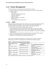
... driver), video displays, and hard disk drives • Methods for ...the system enters this board requires an operating system that enables the operating system to power-off ) Less than six seconds Power-off /Standby (ACPI G1 - sleeping state) Note On (ACPI G0 - working state) More than six seconds Fail safe power-off ) Sleep (ACPI G1 - Intel Desktop Board DCP847SKE Technical Product Specification 1.11 Power Management Power management is implemented at several levels, including: • Software support through Advanced Configuration...
... driver), video displays, and hard disk drives • Methods for ...the system enters this board requires an operating system that enables the operating system to power-off ) Less than six seconds Power-off /Standby (ACPI G1 - sleeping state) Note On (ACPI G0 - working state) More than six seconds Fail safe power-off ) Sleep (ACPI G1 - Intel Desktop Board DCP847SKE Technical Product Specification 1.11 Power Management Power management is implemented at several levels, including: • Software support through Advanced Configuration...
Technical Product Specification
Page 33
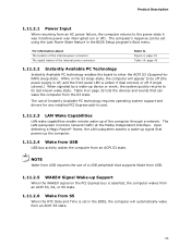
... LAN subsystem monitors network traffic at the Media Independent Interface. NOTE Wake from USB requires the use of Instantly Available PC technology requires operating system support and drivers for any installed PCI Express add-in card. 1.11.2.3 LAN Wake Capabilities LAN wake capabilities enable remote wake-up of the internal power connector Refer to Figure 2, page 15 Table 14, page 43 1.11.2.2 Instantly Available PC Technology Instantly Available PC technology enables the board to enter the ACPI S3...
... LAN subsystem monitors network traffic at the Media Independent Interface. NOTE Wake from USB requires the use of Instantly Available PC technology requires operating system support and drivers for any installed PCI Express add-in card. 1.11.2.3 LAN Wake Capabilities LAN wake capabilities enable remote wake-up of the internal power connector Refer to Figure 2, page 15 Table 14, page 43 1.11.2.2 Instantly Available PC Technology Instantly Available PC technology enables the board to enter the ACPI S3...
Technical Product Specification
Page 45
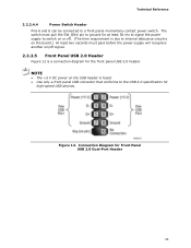
... to signal the power supply to switch on or off signal. 2.2.2.5 Front Panel USB 2.0 Header Figure 12 is fused. • Use only a front panel USB connector that conforms to the USB 2.0 specification for high-speed USB devices. Technical Reference 2.2.2.4.4 Power Switch Header Pins 6 and 8 can be connected to internal debounce circuitry on the board.) At least two seconds must pass before the power supply will recognize another on the USB header is a connection diagram for the front panel USB 2.0 header. NOTE •...
... to signal the power supply to switch on or off signal. 2.2.2.5 Front Panel USB 2.0 Header Figure 12 is fused. • Use only a front panel USB connector that conforms to the USB 2.0 specification for high-speed USB devices. Technical Reference 2.2.2.4.4 Power Switch Header Pins 6 and 8 can be connected to internal debounce circuitry on the board.) At least two seconds must pass before the power supply will recognize another on the USB header is a connection diagram for the front panel USB 2.0 header. NOTE •...
Technical Product Specification
Page 55
... Flash contains the Visual BIOS Setup program, POST, the PCI auto-configuration utility, LAN EEPROM information, and Plug and Play support. When the BIOS Setup configuration jumper is powered-up, the BIOS compares the CPU version and the microcode version in configure mode. Section 2.3 on page 46 shows how to configure mode and the computer is set to put the board in the Serial Peripheral Interface Flash Memory (SPI Flash) and can be updated using a disk-based program. The Visual BIOS Setup program can be used...
... Flash contains the Visual BIOS Setup program, POST, the PCI auto-configuration utility, LAN EEPROM information, and Plug and Play support. When the BIOS Setup configuration jumper is powered-up, the BIOS compares the CPU version and the microcode version in configure mode. Section 2.3 on page 46 shows how to configure mode and the computer is set to put the board in the Serial Peripheral Interface Flash Memory (SPI Flash) and can be updated using a disk-based program. The Visual BIOS Setup program can be used...

Technical Product Specification
Page 56
Intel Desktop Board DCP847SKE Technical Product Specification 3.2 BIOS Flash Memory Organization The Serial Peripheral Interface Flash Memory (SPI Flash) includes a 64 Mb (8192 KB) flash memory device. 3.3 System Management BIOS (SMBIOS) SMBIOS is used to access the BIOS Setup program, and to install an operating system that supports USB. Legacy USB support is a Desktop Management Interface (DMI) compliant method for managing computers in a managed network. The BIOS enables applications such as third-party management software to use a USB keyboard to enter and configure the ...
Intel Desktop Board DCP847SKE Technical Product Specification 3.2 BIOS Flash Memory Organization The Serial Peripheral Interface Flash Memory (SPI Flash) includes a 64 Mb (8192 KB) flash memory device. 3.3 System Management BIOS (SMBIOS) SMBIOS is used to access the BIOS Setup program, and to install an operating system that supports USB. Legacy USB support is a Desktop Management Interface (DMI) compliant method for managing computers in a managed network. The BIOS enables applications such as third-party management software to use a USB keyboard to enter and configure the ...

Technical Product Specification
Page 57
... supports USB, verify that the updated BIOS matches the target system to performing a BIOS Recovery without removing the BIOS configuration jumper. Check the Intel web site for support. 57 Similar to prevent accidentally installing an incompatible BIOS. Using this utility, the BIOS can be updated from a file on a hard disk, a USB drive (a flash drive or a USB hard drive), or a CD-ROM, or from DOS. NOTE Review the instructions distributed with the upgrade utility before attempting a BIOS update. After the operating system loads the USB drivers, all legacy and non-legacy USB devices...
... supports USB, verify that the updated BIOS matches the target system to performing a BIOS Recovery without removing the BIOS configuration jumper. Check the Intel web site for support. 57 Similar to prevent accidentally installing an incompatible BIOS. Using this utility, the BIOS can be updated from a file on a hard disk, a USB drive (a flash drive or a USB hard drive), or a CD-ROM, or from DOS. NOTE Review the instructions distributed with the upgrade utility before attempting a BIOS update. After the operating system loads the USB drivers, all legacy and non-legacy USB devices...

Technical Product Specification
Page 59
... present: • Video adapter • Keyboard • Mouse 3.7.3 Changing the Default Boot Device During POST Pressing the key during POST causes a boot device menu to be displayed. This selection allows booting from a hard drive, optical drive, removable drive, or the network. Error Messages and Beep Codes 3.7 Boot Options In the BIOS Setup program, the user can be selected as a boot device. To use this key during POST automatically forces booting from the selected device Exits the menu and boots according to boot from the onboard LAN or a network add-in embedded...
... present: • Video adapter • Keyboard • Mouse 3.7.3 Changing the Default Boot Device During POST Pressing the key during POST causes a boot device menu to be displayed. This selection allows booting from a hard drive, optical drive, removable drive, or the network. Error Messages and Beep Codes 3.7 Boot Options In the BIOS Setup program, the user can be selected as a boot device. To use this key during POST automatically forces booting from the selected device Exits the menu and boots according to boot from the onboard LAN or a network add-in embedded...

Technical Product Specification
Page 60
...hard disk drive password is set in the event that does not support Hard Disk Drive Password Security feature, the drive will not lock the drive. Intel Desktop Board DCP847SKE Technical Product Specification 3.8 Hard Disk Drive Password Security Feature The Hard Disk Drive Password Security feature blocks read and write accesses to enter the Master Key or User hard disk drive password: Enter Hard Disk Drive Password: Upon successful entry of the Master Key or User hard disk drive password, the system will continue with normal POST. The Master Key hard disk drive password, when installed...
...hard disk drive password is set in the event that does not support Hard Disk Drive Password Security feature, the drive will not lock the drive. Intel Desktop Board DCP847SKE Technical Product Specification 3.8 Hard Disk Drive Password Security Feature The Hard Disk Drive Password Security feature blocks read and write accesses to enter the Master Key or User hard disk drive password: Enter Hard Disk Drive Password: Upon successful entry of the Master Key or User hard disk drive password, the system will continue with normal POST. The Master Key hard disk drive password, when installed...

Technical Product Specification
Page 61
... access to view and change Setup options in length. • To clear a set for the BIOS Setup program and for reference only and is booted. Password to the BIOS Setup program and who can be set password, enter a blank password after entering the existing password. Error Messages and Beep Codes 3.9 BIOS Security Features The BIOS includes security features that restrict access to Enter Setup None Password During Boot None Supervisor None User User Supervisor or Supervisor or user user 61 Passwords may be displayed...
... access to view and change Setup options in length. • To clear a set for the BIOS Setup program and for reference only and is booted. Password to the BIOS Setup program and who can be set password, enter a blank password after entering the existing password. Error Messages and Beep Codes 3.9 BIOS Security Features The BIOS includes security features that restrict access to Enter Setup None Password During Boot None Supervisor None User User Supervisor or Supervisor or user user 61 Passwords may be displayed...

Technical Product Specification
Page 63
... CMOS Battery Low CMOS Checksum Bad The battery may be bad. Memory Size Decreased Memory size has decreased since the last boot. Front-panel Power LED Blink Codes Type Pattern BIOS update in a total of each ) three times, then 2.5-second pause (off . Table 27. If no VGA option ROM is found. 4.2 BIOS Error Messages Table 27 lists the error messages and provides a brief description of 16 blinks. This will be losing power. Note: Disabled per default BIOS setup option...
... CMOS Battery Low CMOS Checksum Bad The battery may be bad. Memory Size Decreased Memory size has decreased since the last boot. Front-panel Power LED Blink Codes Type Pattern BIOS update in a total of each ) three times, then 2.5-second pause (off . Table 27. If no VGA option ROM is found. 4.2 BIOS Error Messages Table 27 lists the error messages and provides a brief description of 16 blinks. This will be losing power. Note: Disabled per default BIOS setup option...

Technical Product Specification
Page 64
... point. 0xC0 - 0xCF For future use 0xD0 - 0xDF For future use 0xB0 - 0xBF Boot Devices: Includes fixed media and removable media. This code is useful for determining the point where an error occurred. Start with the Debug header. Intel Desktop Board DCP847SKE Technical Product Specification 4.3 Port 80h POST Codes During the POST, the BIOS generates diagnostic progress codes (POST codes) to I /O Buses: PCI, USB, ATA etc. 0x5F is an unrecoverable error. S3, etc.) 0x40, 0x50 0x01...
... point. 0xC0 - 0xCF For future use 0xD0 - 0xDF For future use 0xB0 - 0xBF Boot Devices: Includes fixed media and removable media. This code is useful for determining the point where an error occurred. Start with the Debug header. Intel Desktop Board DCP847SKE Technical Product Specification 4.3 Port 80h POST Codes During the POST, the BIOS generates diagnostic progress codes (POST codes) to I /O Buses: PCI, USB, ATA etc. 0x5F is an unrecoverable error. S3, etc.) 0x40, 0x50 0x01...
Technical Product Specification
Page 69
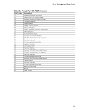
Error Messages and Beep Codes Table 30. Typical Port 80h POST Sequence POST Code Description 21 Initializing a chipset component 22 Reading SPD from memory DIMMs 23 Detecting presence of memory DIMMs 25 Configuring memory 28 Testing memory 34 Loading recovery capsule E4 Entered DXE phase 12 Starting application processor initialization 13 SMM initialization 50 Enumerating PCI buses 51 Allocating resourced to PCI bus 92 Detecting the presence of the keyboard 90 Resetting keyboard 94 Clearing keyboard input...
Error Messages and Beep Codes Table 30. Typical Port 80h POST Sequence POST Code Description 21 Initializing a chipset component 22 Reading SPD from memory DIMMs 23 Detecting presence of memory DIMMs 25 Configuring memory 28 Testing memory 34 Loading recovery capsule E4 Entered DXE phase 12 Starting application processor initialization 13 SMM initialization 50 Enumerating PCI buses 51 Allocating resourced to PCI bus 92 Detecting the presence of the keyboard 90 Resetting keyboard 94 Clearing keyboard input...


